

Page 1
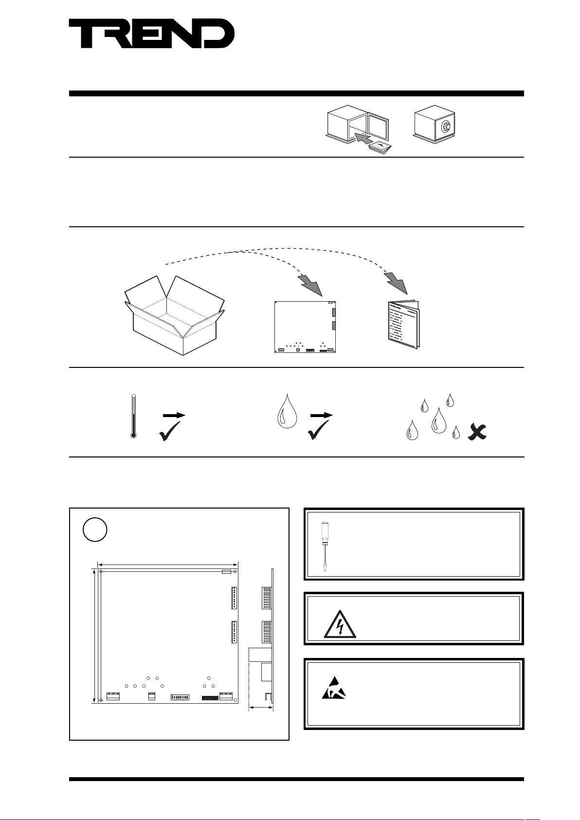
Communications Node Controller
Important: Retain these instructions
Contents
1 Unpacking 1
2 Storage 1
3 Installation Instructions 1
1 Unpacking
J8
Installation Instructions
CNC2
3.1 Installation Instructions - Mounting 1
3.2 Installation Instructions - Configuration 5
4 Disposal 8
ET1
J16
DevB
J15
DevA
J7
LanA
CNC2 Installation
Instructions TG200262
2 Storing
-10 °C 14 °F
+50 °C
+122 °F
HO
3 Installation Installation
3.1 Installation Instructions - Mounting
Dimensions
1
160 mm (6.3”)
E T 1
J 1 6
D e v B
J 1 5
D e v A
151 mm (5.95”)
J 8
J 7
L a n A
33 mm
(1.3”)
0
95 %RH
2
It is recommended that the installation should
comply with the HSE Memorandum of Guidance
on Electricity at Work Regulations 1989.
For USA install equipment in accordance with
National Electric Code.
WARNING:Opening the panel may expose dangerous
voltages.
417-IEC-5036
Caution: The CNC2 contains static sensitive devices.
Suitable anti-static precautions should be
taken throughout this operation to prevent
damage to the unit.
BS EN100015/1 Basic Specification: protection of
electostatic sensitive devices.
CNC2 Installation Instructions TG200262 Issue 2, 2/10/08
1
Page 2
CNC2 Installation Instructions
0
I
J7
ET1
J16
DevB
J15
DevA
J8
LanA
HO
2
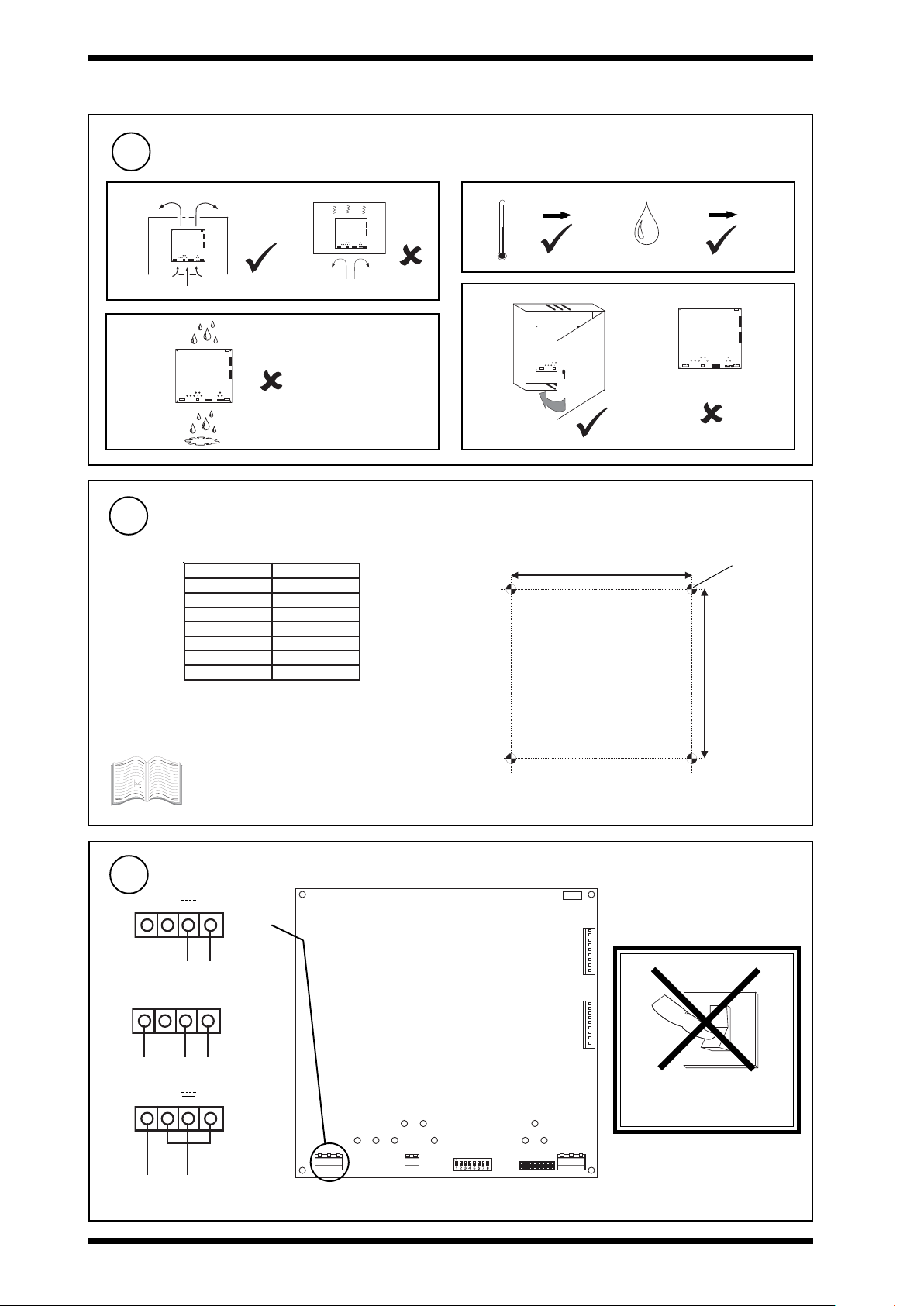
3.1 Installation Instructions - Mounting (continued)
Requirements
2
a
ET1
J16
Dev B
ET1
J16
Dev B
J15
Dev A
J7
J8
Lan A
J15
Dev A
J7
J8
Lan A
b
0 °C
32 °F
d
c
DevB
DevA
LanA
Mount the Node
3
The CNC2 can be fitted into enclosures and controllers as shown in the table below:
BBTEN/BTEN
+201/+101QI
+111QI
+131QI
152QI
052QI
242/142QI
332/132QI
*
*
J8
+45 °C
113 °F
ET1
J16
J16
DevB
DevB
J15
J15
DevA
DevA
J7
LanA
151 mm (5.9”)
0 %RH 95 %RH
ET 1
J1 6
De v B
J1 5
De v A
J8
J7
La n A
4 off 4 mm
(0.16”)
* CNC2 board fits with 3 screws in normal node position
or fits in NDP position. Must use NDP position if RDS
141 mm (5.6”)
fitted.
See appropriate enclosure/controller
installation instructions for more details about
node installation.
Connecting Power
4
CNC2 consumption <=5 VA
E T 1
~ ~ 0V
24 Vdc
+24 V
0V
~ ~ 0V
J 1 6
D e v B
J 1 5
18-0-18 Vac
18 18 0
D e v A
~ ~ 0V
18 Vac
DO NOT APPLY
POWER
(isolated)
J 8
18 Vac
2
terminal size 0.5 to 2.5 mm
2
(14 to 20 AWG)
CNC2 Installation Instructions TG200262 Issue 2, 2/10/08
J 7
L a n A
Page 3
Installation Instructions CNC2
T
R
T
R
T
R
T
R
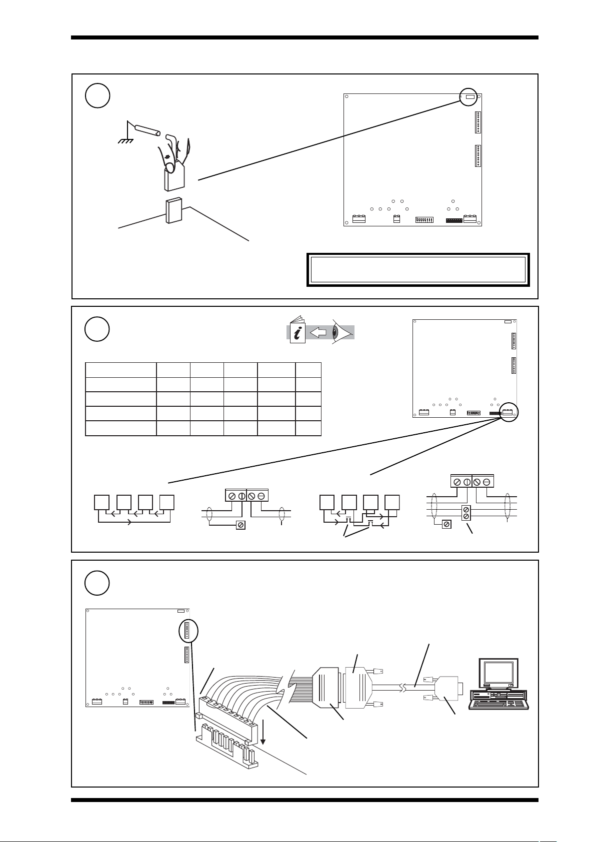
3.1 Installation Instructions - Mounting (continued)
Connecting Earth
5
Connect Network (Lan A)
6
elbaCduab2k1duab8k4duab6k9duab2k91
2819nedleB
7029nedleB
002/FH/22/1/1/PTdnerT
)1678nedleB(
002/FH/22/2/2/PTdnerT
)3278nedleB(
terminal size 0.5 to 2.5 mm
m0001
m0001
m0001
m0001
m0001
)sdy0901(
m0001
)sdy0901(
m0001
)sdy0901(
m0001
)sdy0901(
2
(14 to 20 AWG)
WARNING: This apparatus must be earthed
Network Engineering Manual, 92-1735.
fo.oN
m0001
)sdy0901(
m0001
)sdy0901(
m007
)sdy0901(
m005
)sdy0901(
m007
)sdy0901(
m005
)sdy0901(
m053
)sdy567(
m052
)sdy545(
seriW
2
)sdy567(
2
)sdy545(
2
)sdy083(
4
)sdy072(
E T 1
J 1 6
D e v B
J 1 5
D e v A
J 8
J 8
J 7
L a n A
E T 1
J 1 6
D e v B
J 1 5
D e v A
J 7
L a n A
Polarity independent
2 wire
Connect to Local Device
7
(Device B - RS232)
J16
J 8
L A N A
L A N A
T -
R +
R
R
E T 1
J 1 6
Dev B
D e v B
J 1 5
D e v A
T + R -
e a r t h b u s
T
T
X
cables not supplied with unit
10 Way, Molex, Female
links between pins 2-4, 3-5
4 wire
R
T
additional terminals
25 Way, D type, Male
R
R
T
T
T
T
T
R
R
R
CABLE/58-0750
e a r t h b u s
T -
R +
T + R -
additional terminals
Device B
local device
(e.g. PC)
PC's
T
T
R
R
X
COM port
J 7
L a n A
25 Way, D type, Female
1
CABLE/EJ100179A001
9 Way, D type, Female
CNC2 Installation Instructions TG200262 Issue 2, 2/10/08
3
Page 4
CNC2 Installation Instructions
3.1 Installation Instructions - Mounting (continued)
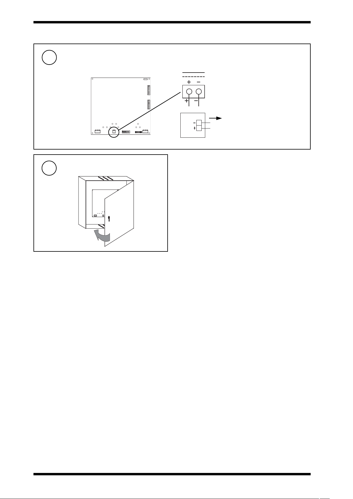
Connect Auxiliary Supply Output
8
CNC2
24 V
24 V
I max = 150 mA
Close Panel/Box
9
terminal size 0.5 to 2.5 mm
E T 1
J 8
J 7
2
J 1 6
D e v B
J 1 5
D e v A
L a n A
AUX
ET1
J16
J16
DevB
DevB
J15
J15
DevA
DevA
J8
J7
LanA
4
CNC2 Installation Instructions TG200262 Issue 2, 2/10/08
Page 5

Installation Instructions CNC2
3.2 Installation Instructions - Configuration
Switch off and open panel/covers
1
Set the Network Address
2
(Lan A)
e.g.
O N
A D D R E S S
D U M B
N O R M
Address = 2+16+64= 82
SET
NOT SET
WARNING: Opening the panel may expose
dangerous voltages.
417-IEC-5036
ET1
J16
J16
DevB
DevB
J15
J15
O
I
J8
DevA
DevA
J7
LanA
Caution: The CNC2 contains static sensitive
devices. Suitable anti-static precautions
should be taken throughout this operation
to prevent damage to the unit.
BS EN100015/1 Basic Specification: protection of
electostatic sensitive devices.
Set Network Baud Rate
3
(Baud A)
E T 1
J 1 6
D e v B
J 1 5
D e v A
J 8
J 7
L a n A
B a u d B B a u d A
J 8
E T 1
J 1 6
D e v B
J 1 5
D e v A
J 7
L a n A
Address = D
= D
CNC2
move link to
set baud rate
Network Baud Rate = R1
= R1
= D
/
= D
/
e.g 9k6
= R1
= R1
address
4
e.g 19k2
= D
1, 4 to 9, 11 to 114
0, 2, 3, 10 or >119
/
B a u d B B a u d A
Set Device B connector (RS232) to Local Device Baud Rate
(Baud B)
move link to
set baud rate
B a u d B B a u d A
Device B (J16) to local device Baud Rate = R2
= R2
= R2
CNC2
B a u d B B a u d A
= R1
E T 1
J 1 6
D e v B
J 1 5
D e v A
J 8
J 7
L a n A
CNC2 Installation Instructions TG200262 Issue 2, 2/10/08
5
Page 6

CNC2 Installation Instructions
3.2 Installation Instructions - Configuration (continued)
E T 1
J 1 6
D e v B
J 1 5
D e v A
5
Switch On
Check Node Controller
6
a PWR ON
0
(green)
Check supply
J 8
J 7
L a n A
I
b W/DOG
(red)
CNC2 Faulty
7
L A N A
T - T + R - R +
Check Network
J 8
OKA
CNC2 Faulty
a RXA
(yellow)
E T 1
J 1 6
D e v B
J 1 5
D e v A
J 7
L a n A
b TXA
(yellow)
c OKA
?
C N C 2
C N C 2
?
(green)
Network Address Invalid
0, 2, 3 or >119
✘
CNC2
L A N A
T - T + R - R +
OKA
Check network cabling
for short circuits with a
multimeter (NOT Megger)
Check baud rate
O
I
Power up other nodes until
faulty node is found
(OK ). Correct fault.
6
CNC2 Installation Instructions TG200262 Issue 2, 2/10/08
Page 7
Installation Instructions CNC2
3.2 Installation Instructions - Configuration (continued)
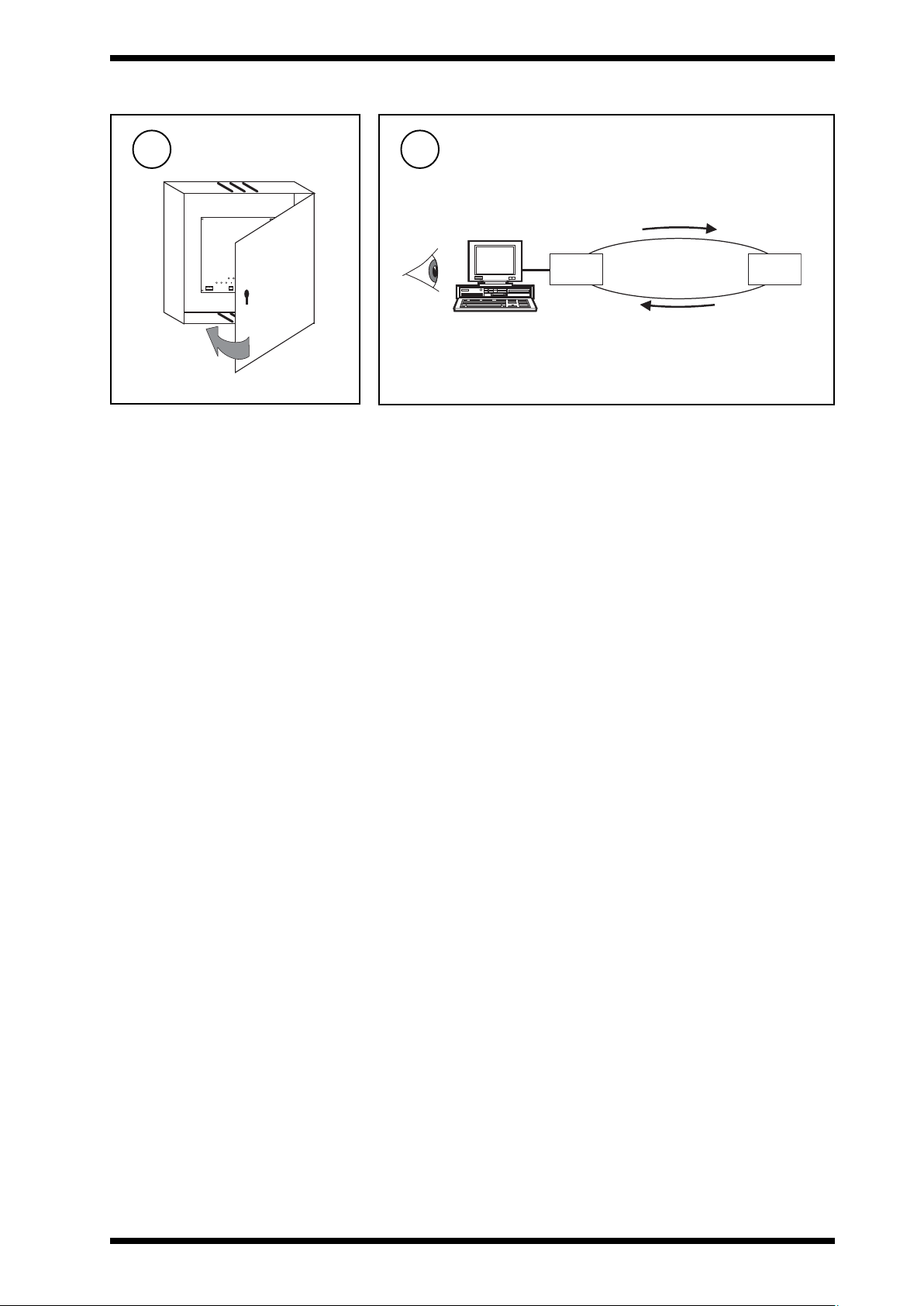
Close panel/covers
8
J8
Check System
9
ET1
J16
J16
DevB
DevB
J15
J15
DevA
DevA
J7
LanA
T=X °C
CNC2
Lan A
temperature ?
IQ
T=X °C
CNC2 Installation Instructions TG200262 Issue 2, 2/10/08
7
Page 8

CNC2 Installation Instructions
4 Disposal
WEEE Directive :
At the end of their useful life the packaging and
product should be disposed of by a suitable
Do not dispose of with normal household waste.
Do not burn.
recycling centre.
Please send any comments about this or any other Trend technical publication to techpubs@trendcontrols.com
© 2008 Honeywell Technologies Sàrl, ECC Division. All rights reserved. Manufactured for and on behalf of the Environmental and Combustion Controls
Division of Honeywell Technologies Sàrl, Ecublens, Route du Bois 3, Switzerland by its Authorized Representative, Trend Control Systems Limited.
Trend Control Systems Limited reserves the right to revise this publication from time to time and make changes to the content hereof without
obligation to notify any person of such revisions or changes.
Trend Control Systems Limited
P.O. Box 34, Horsham, West Sussex, RH12 2YF, UK. Tel:+44 (0)1403 211888 Fax:+44 (0)1403 241608 www.trend-controls.com
Trend Control Systems USA
6670 185th Avenue NE, Redmond, Washington 98052, USA. Tel: (425)897-3900, Fax: (425)869-8445 www.trend-controls.com
8
CNC2 Installation Instructions TG200262 Issue 2, 2/10/08
 Loading...