

Page 1
Important: Retain these instructions
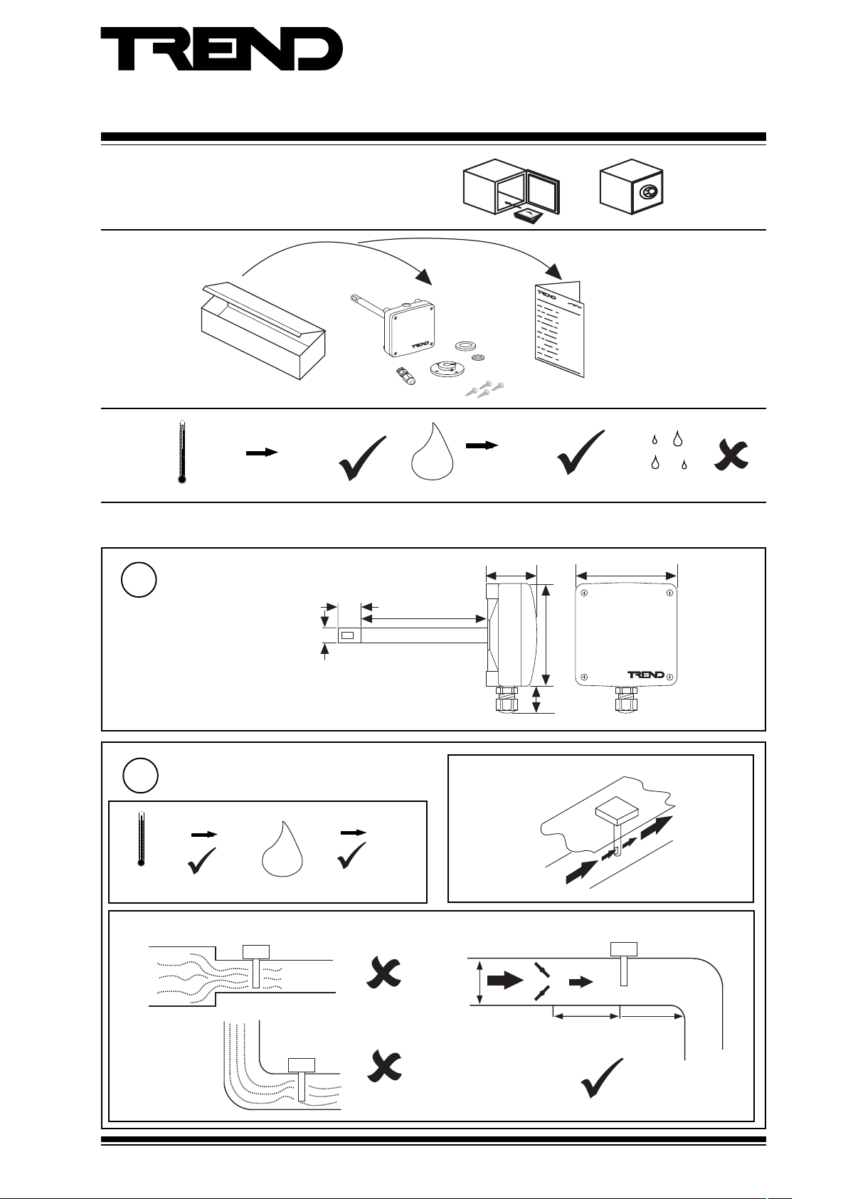
Unpacking
Installation Instructions
AV/D
Duct Air Velocity Sensor
Installation Instructions,
TG200504
Storing
-20 °C
(-4 °F)
Installation
Dimensions
1
Requirements
2
a
-10 °C
(14 °F)
Protection: IP65, NEMA12
+50 °C
(122 °F)
+50 °C
(+122 °F)
Ø 12 mm
(0.47”)
H O
2
0 %RH
18 mm
(0.71”)
H O
100 mm (3.94”)
95 %RH
0
2
95 %RH
40 mm (1.57”)
b Align sensor
80 mm (3.15”)
80 mm (3.15”)
20 mm
(0.79”)
c Smooth flow
D
AV/D Duct Air Velocity Sensor Installation Instructions TG200504 Issue 2 11/07/08
>6D
>3D
1
Page 2
AV/D Installation Instructions
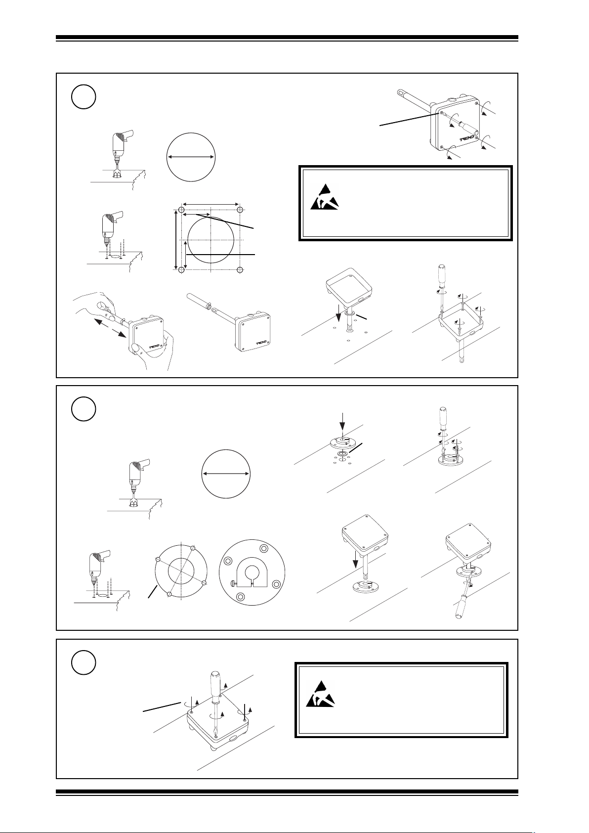
Installation (continued)
Mount sensor to duct if mounting direct
3
a drill probe hole
Ø 13 mm
b drill mounting holes
64 mm (2.52”)
c remove protective cover
(0.52”)
50 mm (1.97”)
25 mm
(0.97”)
32 mm
(1.26”)
d remove cover
loosen 4 screws
Caution: This unit contains static sensitive devices.
BS EN100015/1 Basic Specification: protection of
electrostatic sensitive devices.
e
Suitable anti-static precautions should be
taken throughout the operation to prevent
damage to the units.
f
foam gasket
(small)
tighten 4 screws
(provided)
Mount sensor on duct if using adjustable
4
depth mounting flange
a drill flange hole
b drill mounting holes
φ44 mm
(1.73”)
Remove cover
5
if not already removed
loosen 4 screws
27 °
Ø 22 mm
(0.87”)
c mount flange
foam gasket
(large)
e
Caution: This unit contains static sensitive devices.
Suitable anti-static precautions should be
taken throughout the operation to prevent
damage to the units.
BS EN100015/1 Basic Specification: protection of
electrostatic sensitive devices.
d
tighten 4 screws
(provided)
f adjust depth
2
AV/D Duct Air Velocity Sensor Installation Instructions TG200504 Issue 2 11/07/08
Page 3

Installation Instructions AV/D
1 2 3
Installation (continued)
Set measuring range
6
if default unsatisfactory
default = 0 to 10 m/s (OK for IQL17/VAV)
no link
1 2 3
Set response time
8
if default unsatisfactory
default = slow (2s) (OK for IQL17/VAV)
S
1 2 3
no link
H I
10 m/s
M I D
15 m/s
20 m/s
slow (2 s)
fast (0.2 s)
Set output signal
7
if default unsatisfactory
default = 0 to 10 V (OK for IQL17/VAV)
1
1 2 3
1
Screw in cable gland
9
0 to 10 V
U
4 to 20 mA
U
10
11
if IQ
Insert cable in gland
Wire to controller
AV/D IQ1 & IQ2
V+
1
GND
2
AV
3
terminate screen at IQ
AV/D
V+
1
GND
2
AV
3
A U X ( 2 4 V d c )
C O M ( 0 V )
I N
IQ3
24 V Aux
0 (0V)
N (in)
+ (24 v)
V (default)
or Ix
Analogue input channel
linked for Voltage
}
(default) or Current
External (if set in step 7).
N
if IQL17/VAV
IQL17/VAV
2 4 V a c
R E T
4
I N 2
I N 1
A I
C O M
5
0 V
2 1 2 7 2 8
2 2 2 3 2 4 2 5 2 6
V+
GND
1 2 3
AV/D
I N 5
I N 3
I N 4
C
0 - 1 0 V
AV
Note that screened cable is not required
for sensor wiring to IQLs. If screened
cable is used it must be terminated at
the controller to its supply earth.
Note that 24 V supply to sensor should be from 24 V auxiliary output power supply or external supply.
AV/D Duct Air Velocity Sensor Installation Instructions TG200504 Issue 2 11/07/08
3
Page 4

AV/D Installation Instructions
Installation (continued)
Replace sensor cover
12
tighten 4 screws
Switch on supply to controller
13
O
I
Note that if AV/D is left at default link settings, IQL17/VAV
Configure IQ (not IQL17/VAV)
14
I Q
or
Set up sensor scaling
15
If IQ
It is recommended to use SET (Software Tool) for the setting of the sensor type module. For all IQ2 series controllers with
firmware version 2.1 or greater, or IQ3 series controllers use the appropriate SET Unique Sensor References from the
following:
dekniL
V01ot0
7petS
ticoleVsm02IyticoleV
requires no sensor scaling configuration.
I Q
IQ Configuration Manual 90-1533
sm01VyticoleV
)TLUAFED(
sm51VyticoleVsm51IyticoleV
sm02Vy
dekniL
Am02ot4
7petS
sm01IyticoleV
Alternatively enter scaling manually as
defined in the adjacent table with sensor
type scaling mode set to 5 (characterise).
Note that for IQ3, scaling mode and
exponent do not need to be set up.
For all other controllers see Sensor Scaling
Reference Card TB100521A.
egnaRkniL Y E U L P I1 I2 O1 O2
tluafed
)s/m01(
s/m51
s/m02
tloV,V)stlov(021.01 020 01001
tnerruC,I)tnerruc(221.0102402001
stloV,V)stlov(021.51 020 01051
uc(221.5102402051
tnerruC,I)tnerr
stloV,V)stlov(021.02 020 01002
tnerruC,I)tnerruc(221.0202402002
Disposal
Test system
16
controller
Please send any comments about this or any other Trend technical publication to techpubs@trendcontrols.com
© 2008 Honeywell Technologies Sàrl, ECC Division. All rights reserved. Manufactured for and on behalf of the Environmental and Combustion Controls
Division of Honeywell Technologies Sàrl, Ecublens, Route du Bois 3, Switzerland by its Authorized Representative, Trend Control Systems Limited.
Trend Control Systems Limited reserves the right to revise this publication from time to time and make changes to the content hereof without
obligation to notify any person of such revisions or changes.
Trend Control Systems Limited
P.O. Box 34, Horsham, West Sussex, RH12 2YF, UK. Tel:+44 (0)1403 211888 Fax:+44 (0)1403 241608 www.trend-controls.com
Trend Control Systems USA
6670 185th Avenue NE, Redmond, Washington 98052, USA. Tel: (425)897-3900, Fax: (425)869-8445 www.trend-controls.com
Δ V
WEEE Directive :
At the end of their useful life the packaging
and product should be disposed of by a
suitable recycling centre.
Do not dispose of with normal household waste.
Do not burn.
4
AV/D Duct Air Velocity Sensor Installation Instructions TG200504 Issue 2 11/07/08
 Loading...