

Page 1
Important: Retain these instructions
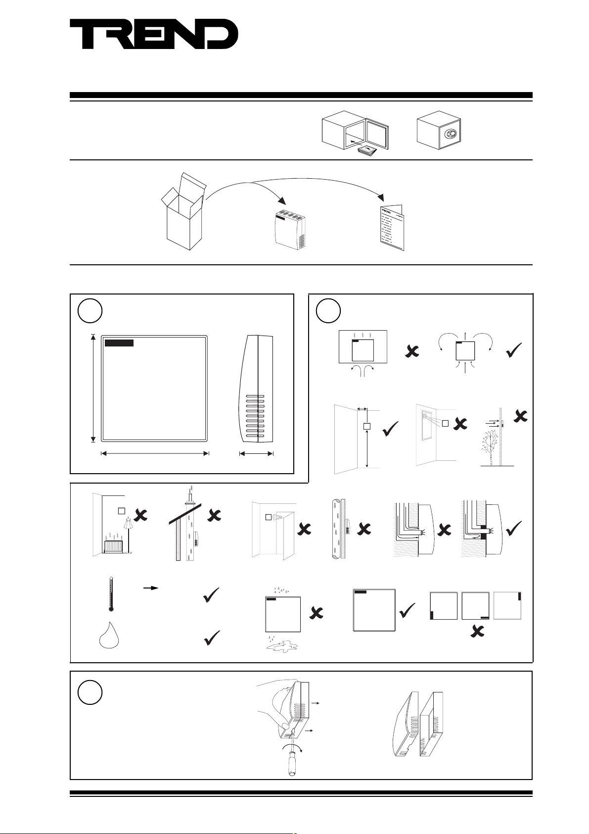
Unpacking
Installation
Installation Instructions
AQ/S
Space Air Quality Sensor
AQ/S Installation Instructions
TG100526A
1
86 mm (3.39”)
e
j
Dimensions
86 mm (3.39”)
f g
18 °C
(64 °F)
+24 °C
(756 °F)
26 mm (1.02”)
2
a
> 50 cm (20”)
b
h
lk
Requirements
c
1.5 m
(5 ft)
i
d
H O
3
AQ/S Installation Instructions TG100526A Issue 2/A 05/06/06
65 %RH ± 5%
2
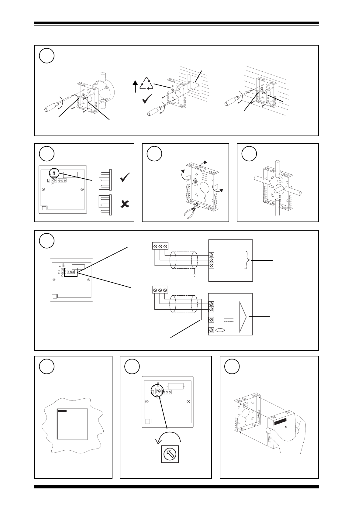
Remove backplate
ab
1
Page 2
AQ/S Installation Instructions
N o r m a l
C a l
L D 1
C a l
N o r m a l
C a l
V R 1
M a x O P 0 V 2 4 V
M i n
D e la y
Installation (Continued)
4
Mount backplate
back box
(BESA)
35 mm (1.38”)
5
Check link
35 mm (1.38”)
C a l
N o r m a l
wall box
FR
ABS
6
as required
60 mm (2.36”)
Remove cutout
wall
35 mm (1.38”)
7
35 mm
(1.38”)
Route cable
8
Wire to Controller
C a l
L D 1
N o r m a l
C a l
V R 1
M a x O P 0 V 2 4 V
M i n
D e l a y
Note that sensor requires 96 mA
from 24 V supply
9
Ensure clean
environment
OP 0V 24V
Sensor
IQ1 & IQ2
24V (AUX)
C (0V)
IN
OP 0V 24V
Sensor
IQ3
0 (0V)
N (in)
24V
N
use auxiliary 24 Vdc output terminal as maximum current = 96 mA
10
Set minimum delay
C a l
L D 1
N o r m a l
C a l
V R 1
M a x O P 0 V 2 4 V
M i n
D e l a y
11
backplate
Loosely assemble unit
IQ analogue
input channel
linked for
voltage (V)
IQ analogue
input channel
linked for
voltage (V)
Clean Air
2
M i n
D e l a y
AQ/S Installation Instructions TG100526A Issue 2/A 05/06/06
Page 3

Installation Instructions AQ/S
Installation (Continued)
12
30 mins
14
a
16
backplate
Wait
13
Remove backplate
Assemble unit
Measure output
b
‘click’
V
15
17
0V
IN
24V
Set delay
C a l
L D 1
N o r m a l
C a l
V R 1
M a x O P 0 V 2 4 V
M i n
D e l a y
Configure IQ
V = 1 to 3 V
V < 1 or > 3V - recalibrate
AQ/S Data Sheet
91-2789
(0 mins)
Min
or
12 mins)
Max
Delay
IQ
IQ
IQ Configuration Manual 90-1533
18
Set up IQ Sensor type
It is recommended to use SET (software tool) for the setting of the sensor type module. For all IQ2 series controllers with
firmware version 2.1 or greater, or IQ3 series controllers, the following SET Unique Sensor Reference should be used:
Air Quality V
If not using SET, use the following table for all IQ2 series controllers of firmware version 2.1 or greater or IQ3 controllers;
for all other IQ controllers see Sensor Scaling Reference Card TB100521A.
tYpe Sensor digI/P Driver Function loGic Loop scHedule seQnc Analog
digBit Knob sWitch Time Zone Oss User addRess intcoN calarM reView Plot
calEndar
= ?
Air Quality (0-100%)
0 = good 100 = bad
Voltage
Yx<CR>
TYPE x
:
=?
S=5 (characterise )
Y=, E=, U=, L=, P=
I1 to I2=, O1 to O2=
Y epyttupnI)stlov(0
E tnenopxE3
U reppU001
L rewoL0
P stnioP2
xxIxO
1 00
2 01001
AQ/S Installation Instructions TG100526A Issue 2/A 05/06/06
3
Page 4

AQ/S Installation Instructions
Installation (Continued)
19
Test system
0 100
I Q
Note that a burn in period of 2 to 3 days is required to ensure a stable and repeatable output.
Disposal
WEEE Directive :
At the end of their useful life the packaging and
product should be disposed of by a suitable
Do not dispose of with normal household waste.
Do not burn.
recycling centre.
Manufactured for and on behalf of the Environmental and Combustion Controls Division of Honeywell Technologies Sàrl, Ecublens, Route
du Bois 37,Switzerland by its Authorized Representative, Trend Control Systems Limited.
Trend Control Systems Limited reserves the right to revise this publication from time to time and make changes to the content
hereof without obligation to notify any person of such revisions or changes.
Trend Control Systems Limited
P.O. Box 34, Horsham, West Sussex, RH12 2YF, UK. Tel:+44 (0)1403 211888 Fax:+44 (0)1403 241608 www.trend-controls.com
Trend Control Systems USA
6670 185th Avenue NE, Redmond, Washington 98052, USA. Tel: (425)869-8400, Fax: (425)869-8445 www.trend-controls.com
4
AQ/S Installation Instructions TG100526A Issue 2/A 05/06/06
 Loading...