

Page 1
Important: Retain these instructions
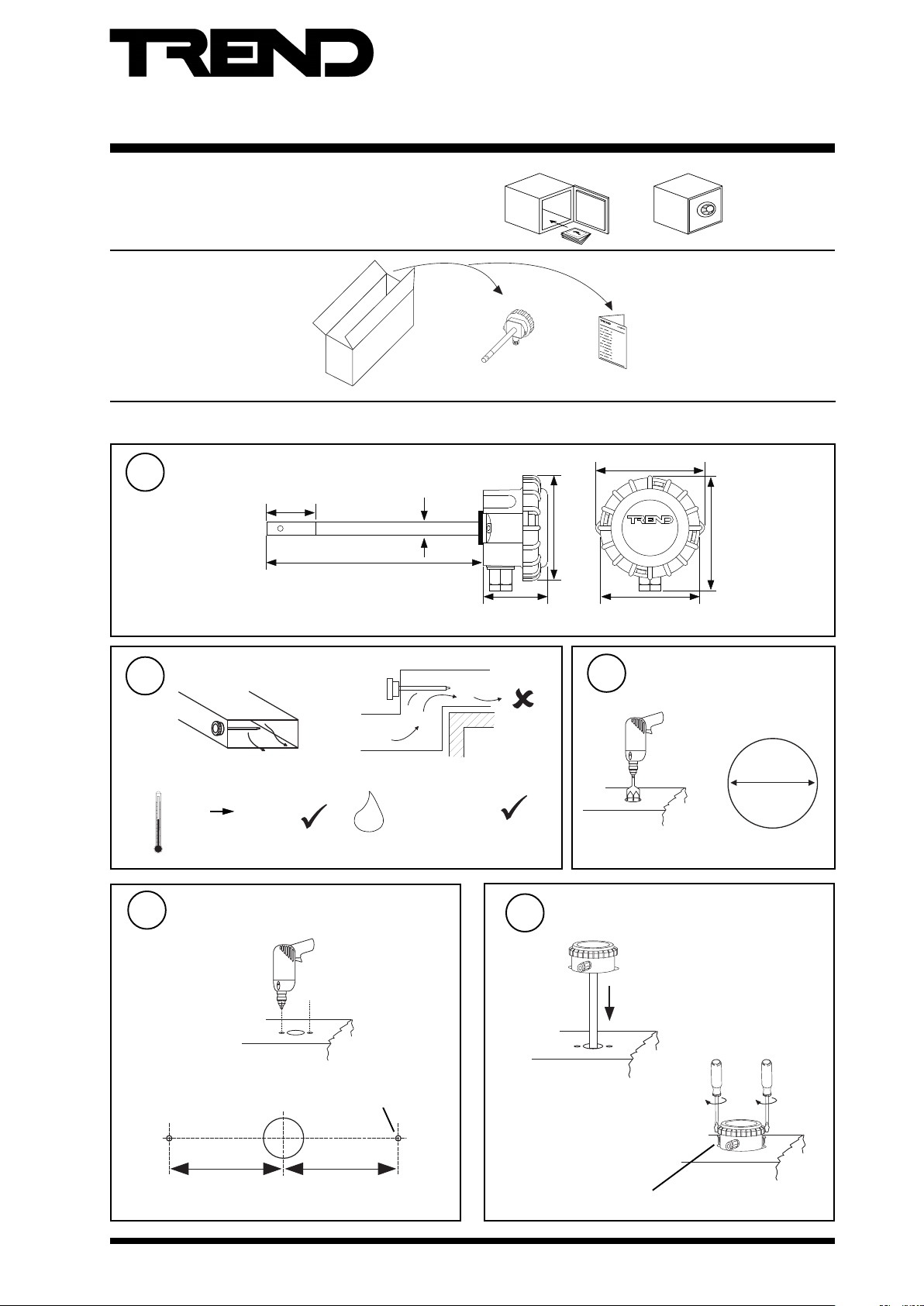
UNPACKING
INSTALLATION
Installation Instructions
AQ/D
Duct Air Quality Sensor
AQ/D Installation Instructions
TG100525A
97 mm (3.82”)
TrendControl Systems
90 mm (3.54”)
85 mm (3.35”)
centres
3
AQ/D
Horsham, UK
105 mm (4.16”)_
Drill hole in duct
1
2
Dimensions
Location
45 mm (1.77”)
12 mm diam (0.47”)
190 mm (7.48”)
57 mm
(2.74”)
b
a
V <= 10 m/s, 33 ft/s
(e.g. return air)
Ø 15 mm
(0.59”)
c
-18 °C
(64 °F)
+24 °C
(75 °F)
65 %RH ± 5 %
HO
2
Protection :IP67, NEMA 6
Prepare duct
4
a
b
42.5mm
(1.67”)
AQ/D Installation Instructions TG100525A Issue 3, 2/03/2009
2 pilot holes
42.5 mm
(1.67”)
Mount Sensor
5
a
b
2 x No 6 x 20 mm screws DIN 7481
1
Page 2
AQ/D Installation Instructions
LD1
VR1
Cal
OP0V24V
Run
VR2
-
+
DELAY
ADJUST
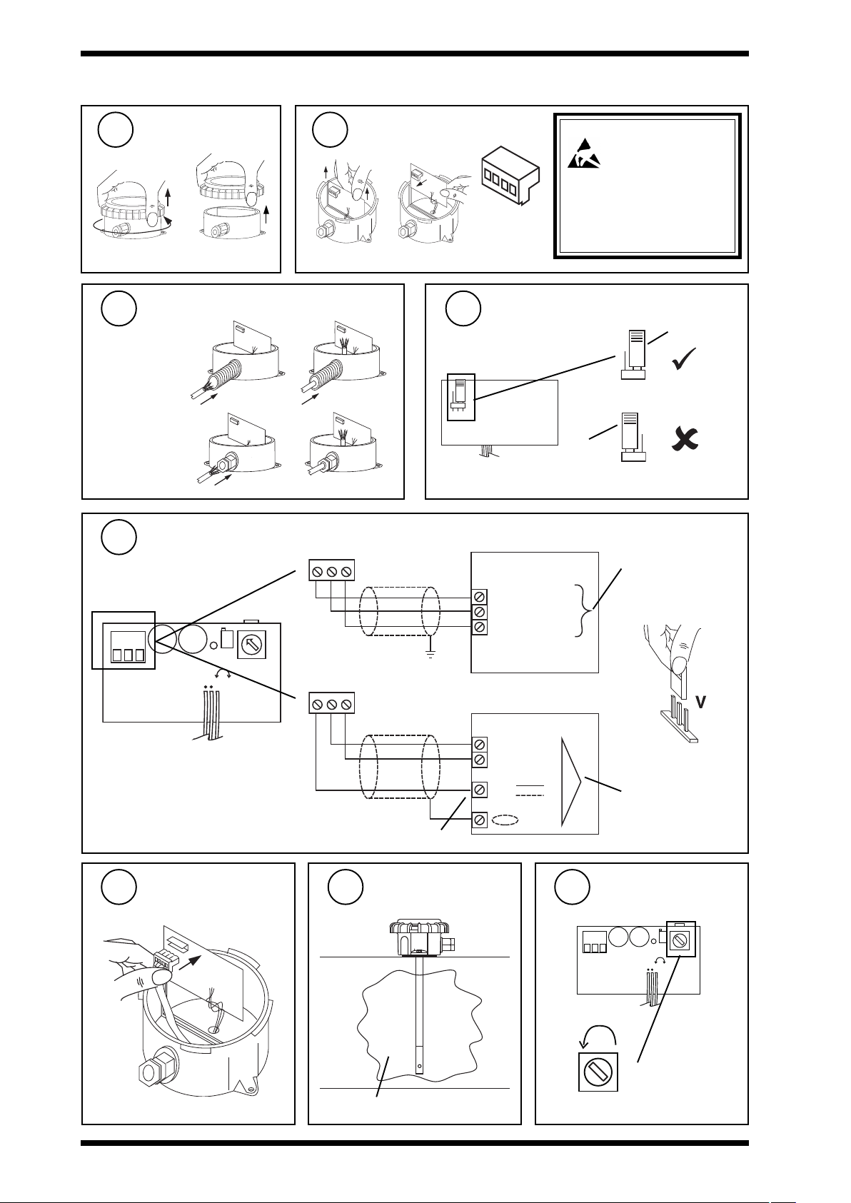
INSTALLATION (Continued)
Remove lid
6 7
Remove Connector
ba
Insert cable through gland
8 9
either use
flexible conduit
or use
M20 cable gland
Wire to Controller
10
C a l
O P0 V2 4 V
R u n
24V 0V OP
Caution: This unit contains static
taken throughtout the operation to
prevent damage to the units.
BS EN100015/1 Basic
Specification: protection of
electrostatic sensitive devices.
Check link is in ‘Run’ position
View of pcb from surface
mount side
Cal
position
IQ2
24V (AUX)
C (0V)
IN
sensitive devices.
Suitable anti-static
precautions should be
Run position
IQ analogue input
channel linked for
voltage (V)
- +
L D 1 V R 1
A D J U S T
- +
Note that sensor requires 96 mA from
24 V supply
Use auxiliary 24 Vdc output terminal as maximum current = 96 mA
Replace connector
11
D E L A Y
V R 2
24V 0V OP
12
Ensure clean
environment
0 (0V)
N (in)
24V
IQ3
N
13
IQ analogue input
channel linked for
voltage (V)
Set minimum delay
-
+
clean air
2
AQ/D Installation Instructions TG100525A Issue 3, 2/03/2009
Delay
Page 3

Installation Instructions AQ/D
LD1
VR1
Cal
OP0V24V
Run
VR2
-
+
DELAY
ADJUST
INSTALLATION (Continued)
14
16
Wait
30 mins
Set delay
15
(0 mins)
Min
Measure Output
(12 mins)
Max
-
+
Delay
V = 1 to 3 V
0V
IN
V < 1 or > 3V - recalibrate
24V
V
AQ/D Data Sheet
91-2747
Replace lid
17
ab c
Note that IP67 (NEMA6) rating is only achieved if the sensor is
correctly installed with cable or conduit connection fully tightened
Configure IQ
18
or
I Q
I Q
IQ Configuration Manual 90-1533
Set up IQ Sensor type
19
It is recommended to use SET (software tool) for the setting of the sensor type module. For all IQ2 series controllers with
firmware version 2.1 or greater, or IQ3 series controllers, the following SET Unique Sensor Reference should be used:
Air Quality V
If not using SET, use the following table for all IQ2 series controllers of firmware version 2.1 or greater or IQ3 controllers;
for all other IQ controllers see Sensor Scaling Reference Card TB100521A.
tYpe Sensor digI/P Driver Function loGic Loop scHedule seQnc Analog
digBit Knob sWitch Time Zone Oss User addRess intcoN calarM reView Plot
calEndar
= ?
Air Quality (0-100%)
0 = good 100 = bad
Voltage
Yx<CR>
TYPE x
:
=?
S=5 (characterise )
Y=, E=, U=, L=, P=
I1 to I2=, O1 to O2=
Y epyttupnI)stlov(0
E tnenopxE3
U reppU001
L rewoL0
P stnioP2
xxIxO
1 00
2 01001
AQ/D Installation Instructions TG100525A Issue 3, 2/03/2009
3
Page 4

AQ/D Installation Instructions
INSTALLATION (Continued)
20
Test System
e.g. return air
Note that a burn in period of 2 to 3 days is required to ensure a stable and repeatable output.
DISPOSAL
WEEE Directive :
At the end of their useful life the packaging and
product should be disposed of by a suitable
recycling centre.
Do not dispose of with normal household waste.
Do not burn.
I Q
0 100
Please send any comments about this or any other Trend technical publication to techpubs@trendcontrols.com
© 2009 Honeywell Technologies Sàrl, ECC Division. All rights reserved. Manufactured for and on behalf of the Environmental and Combustion Controls
Division of Honeywell Technologies Sàrl, Z.A. La Pièce, 16, 1180 Rolle, Switzerland by its Authorized Representative.
Trend Control Systems Limited reserves the right to revise this publication from time to time and make changes to the content hereof without
obligation to notify any person of such revisions or changes.
Trend Control Systems Limited
P.O. Box 34, Horsham, West Sussex, RH12 2YF, UK. Tel:+44 (0)1403 211888 Fax:+44 (0)1403 241608 www.trend-controls.com
Trend Control Systems USA
6670 185th Avenue NE, Redmond, Washington 98052, USA. Tel: (425)897-3900, Fax: (425)869-8445 www.trend-controls.com
4
AQ/D Installation Instructions TG100525A Issue 3, 2/03/2009
 Loading...