

Page 1
Important: Retain these instructions
INSTALLATION ON PC
Installation Instructions
915MDS
Mobile Display Software
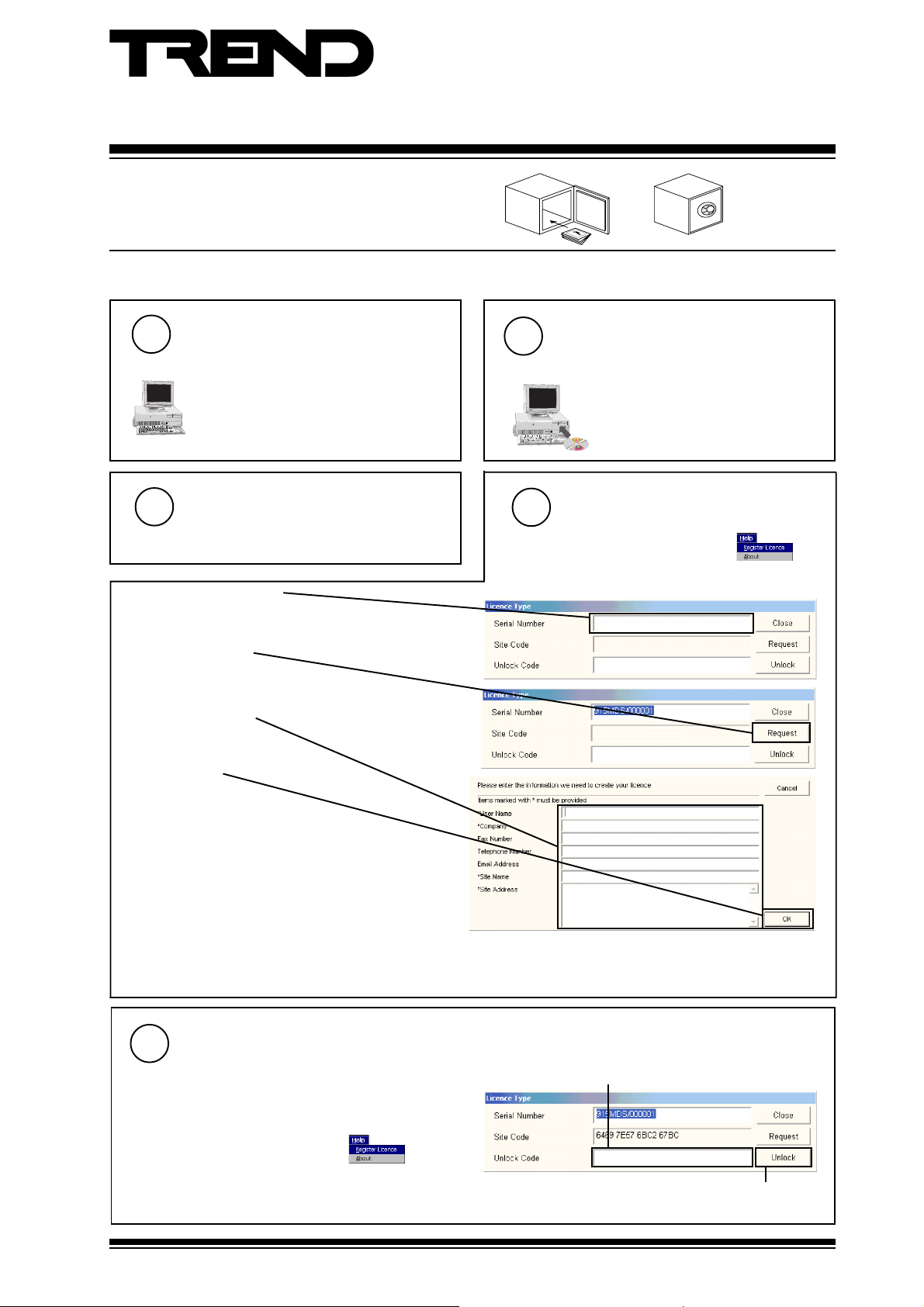
Check PC Configuration
1
Pentium II 200 MHz, 64 Mb RAM, 1 Gb
hard disk, CD-ROM drive, Graphics Card
with 2 Mb of RAM capable of 1024 X
>=
768 (256 colours), 17" monitor,
keyboard, mouse, 1 serial port, 1 parallel
port, and Microsoft Windows 95®/98®.
Run 915
3
a Choose ‘
b Enter the ‘serial number’.
Start\Programs\Trend 915MDS
Ø
c Click on ‘Request’.
Ø
d Enter all the details.
Ø
e Click on ‘OK’.
Install the software
2
a Insert CD b Follow the instructions on
Obtain a Licence
4
’.
a Choose ‘
Help>Register Licence
the screen.
If autorun is disabled, run
Ø
‘setup.exe’ from the root of the
CD.
’.
Ø
f Load ‘Licence txt located in directory in which the
915MDS is installed into Notepad, and print it out.
g Fax the printout to the ‘Trend Customer Services
a Run 915.
Ø
Department on +44 (0) 1403 217392.
If you are entitled to a Type 1 licence, you should also contact your account manager to obtain another unlock code which
will allow access to the additional features. This licence will be time limited, once it expires you can either obtain another
from your account manager, or use the original (Type 1) licence to continue using 915 without the additional features.
Enter the Unlock Code
5
c Enter the ‘Unlock code’.
Ø
Ø
b Choose ‘
Help>Register Licence
’.
Ø
d Click on ‘Unlock’.
915MDS Installation Instructions TG200329 Issue 2/C 31/07/06
1
Page 2
915MDS Installation Instructions
INSTALLATION ON PC (Continued)
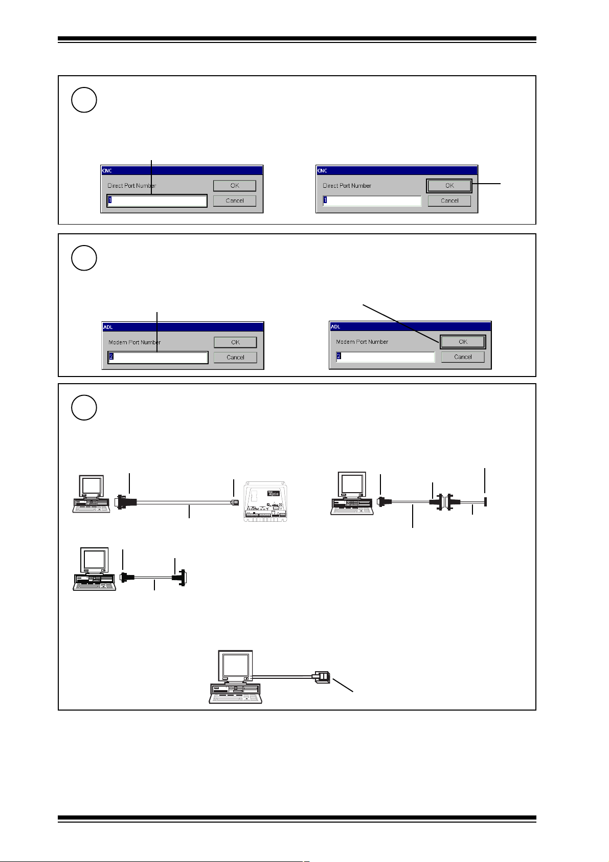
Specify the Comms Port
6
a Choose ‘
Parameters>Direct>Port
’.
b Enter the required port number.
c Click.
Ø
Ø
Specify Local Modem Port
7
a Choose ‘
Parameters>Local Modem>Port
’.
Ø
b Enter the required port number.
c Click.
Ø
Connect to Trend Network
8
This section contains some examples of how the 915 should be connected to the Trend Network. For full details of
connecting the 915 to Trend devices, and the Trend Network see the 915 Manual.
Connection to node controllers/controllers:
Connect the comm port being used by the 915 to the controller’s ‘Local Supervisor’ port using the appropriate cables,
as shown in the diagrams below.
9 way female D type
915
CABLE/EJ101442
9 way male
D type
25 way female
D type
RJ11
OK
Tx
Rx
124
8
163264
9K6
1K2
19K 2
24V
24VAC24VAC24V
23 0 V
1 2 3 4 5
6
7
91011
8
AC
345
9 way male
D type
25 way female
915
CABLE/58-0750
Connection over Ethernet Network
If required, connection can be made to the Trend network over Ethernet to
an EINC. For details of how to do this see the 915 Manual (TE200330).
5 in line
D type
CABLE/78-1172
Connection using a GSM phone
915
CABLE/58-0750
If required, connection can be made to the Trend network using a GSM phone. For
details of how to do this see the 915 Manual (TE200330).
Connection to TMN/ADL using the on board modem:
Connect the telephone socket of the device running 915 as described the instructions provided with the CE Device.
Connection to Telephone socket
Manufactured for and on behalf of the Environmental and Combustion Controls Division of Honeywell Technologies Sàrl, Ecublens, Route
du Bois 37,Switzerland by its Authorized Representative, Trend Control Systems Limited.
Trend Control Systems Limited reserves the right to revise this publication from time to time and make changes to the content
hereof without obligation to notify any person of such revisions or changes.
Trend Control Systems Limited
P.O. Box 34, Horsham, West Sussex, RH12 2YF, UK. Tel:+44 (0)1403 211888 Fax:+44 (0)1403 241608 www.trend-controls.com
Trend Control Systems USA
6670 185th Avenue NE, Redmond, Washington 98052, USA. Tel: (425)869-8400, Fax: (425)869-8445 www.trend-controls.com
2
915MDS Installation Instructions TG200329 Issue 2/C 31/07/06
 Loading...