

TREND 6RM-24VAC User Manual
Six Relay Module (24 Vac/dc)
IN
0V24V
AUTO ON OFF
J1
NONC CNONC CNONC CNONC CNONC CNONC C
AUTO ON OFFJ2AUTO ON OFFJ3AUTO ON OFFJ4AUTO ON OFFJ5AUTO ON OFF
J6
Important: Retain these instructions
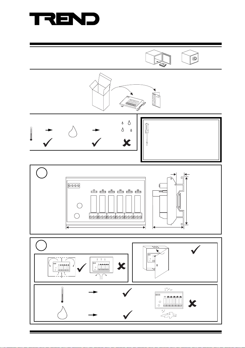
1 UNPACKING
Installation Instructions
6RM/24VAC
6RM/24VAC Installation
Instructions TG200649
2 STORING
-10 °C
(14 °F)
+70 °C
(158 °F)
H O
0 %RH
2
3 INSTALLATION
Dimensions
1
IN 0V 24V
Requirements
2
a
0V24V
IN
J1
J6
AUTO ON OFF
AUTO ON OFFJ2AUTO ON OFFJ3AUTO ON OFFJ4AUTO ON OFFJ5AUTO ON OFF
NONC CNONC CNONC CNONC CNONC CNONC C
95 %RH
J1
AUTO ON OFF
AUTO ON OFFJ2AUTO ON OFFJ3AUTO ON OFFJ4AUTO ON OFFJ5AUTO ON OFF
136 mm (5.35”)
IN0V 24V
J1
J6
AUTO ON OFF
AUTO ON OFFJ2AUTO ON OFFJ3AUTO ON OFFJ4AUTO ON OFFJ5AUTO ON OFF
NONC CNONC CNONC CNONC CNONC CNONC C
It is recommended that the installation
should comply with the HSE
Memorandum of Guidance on
Electricity at Work Regulations 1989.
For USA install equipment in
accordance with the National Electric
Code.
13 mm (0.51”)
J6
82 mm (3.23)
NONC CNONC CNONC CNONC CNONC CNONC C
45 mm (1.77”)
b
The unit is rated as
‘UL916 listed
accessory to open
energy management
equipment.’
c
-10 °C
(14 °F)
0 %RH 90 %RH
H O
6RM/24VAC Six Relay Module (24 Vac/dc) Installation Instructions TG200649 Issue 1/C 02/04/07
2
+50 °C
(122 °F)
IN0V 24V
J1
AUTO ON OFF
AUTO ON OFFJ2AUTO ON OFFJ3AUTO ON OFFJ4AUTO ON OFFJ5AUTO ON OFF
J6
NONC CNONC CNONC CNONC CNONC CNONC C
1
6RM/24VAC Installation Instructions
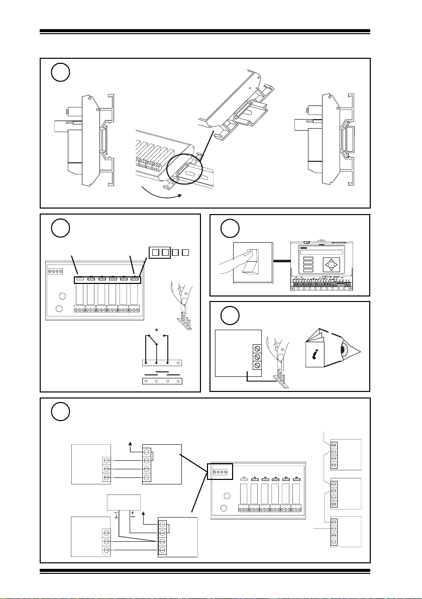
3 INSTALLATION (continued)
Mount on DIN rail
3
a
Set AUTO/ON/OFF links to
4
AUTO
link for relay1link for relay
IN 0V 24V
Note that each link may be
replaced by a three position
(SPDT) switch which will
normally be centre off; this would
be wired as adjacent diagram
(see note step 14).
6
J1
AUTO ON OFF
AUTO ON OFFJ2AUTO ON OFFJ3AUTO ON OFFJ4AUTO ON OFFJ5AUTO ON OFF
J6
NONC CNONC CNONC CNONC CNONC CNONC C
b
A U T O O N O F F
O F F
A U T O O N
A U T O
c
5
Switch off IQ
O
I
IQ
D P
A
B
C
D
1
6 7 8
2 3 4 5
O K
1 7
2 0
1 8
1 6
1 9
LA N
TX R X
V
24 V
1 1
9 1 0
1 2
1 3
1 5
1 4
12 34 56 78 91 0
Ensure IQ Output channel is
6
Analogue set to Voltage V
IQ
24 V
0 V
O N
O F F
OUT
IQ Controller
V
Installation Instructions
Wire module to controller
7
either using IQ 24 Vdc Auxiliary Supply
24 V loop
IQ 6RM
24 V
0 V
OUT
0 V
IN
or using external 24 Vac/dc power supply
Power Supply
24 Vac/dc
24 V loop
IQ
24 V
0 V
OUT
2
6RM/24VAC Six Relay Module (24 Vac/dc) Installation Instructions TG200649 Issue 1/C 02/04/07
24 V
0 V
IN
6RM
24 V
maximum current consumed from supply:
24 Vac 203 mA, 24 Vdc 86 mA
24 V loop
Cable size 0.5 to 2.5 mm2 (14 to
20 AWG), Cu only
IN 0V 24V
J1
AUTO ON OFF
AUTO ON OFFJ2AUTO ON OFFJ3AUTO ON OFFJ4AUTO ON OFFJ5AUTO ON OFF
J6
NONC CNONC CNONC CNONC CNONC CNONC C
24 V
Note that the external 24 V supply should
be isolated or earthed (grounded) to IQ
earth (ground); ensure correct polarity
XRM
XRM
6RM
 Loading...