

TREND 3RM-24VAC User Manual
Three Relay Module (24 Vac/dc)
IN0V 24V
AUTO ON OFFAUTO ON OFF
H
T
J2
J1
FAN/LOW
COOL/MID
RL1
RL2
NONC C NONC C
HEAT/HIGH
RL3
NONC C
AUTO ON OFF
J3
IN
0V24V
AUTO ON OFFAUTO ON OFF
H
T
J2
J1
FAN/LOW
COOL/MID
RL1
RL2
NONC C NONC C
HEAT/HIGH
RL3
NONC C
AUTO ON OFF
J3
Important: Retain these instructions
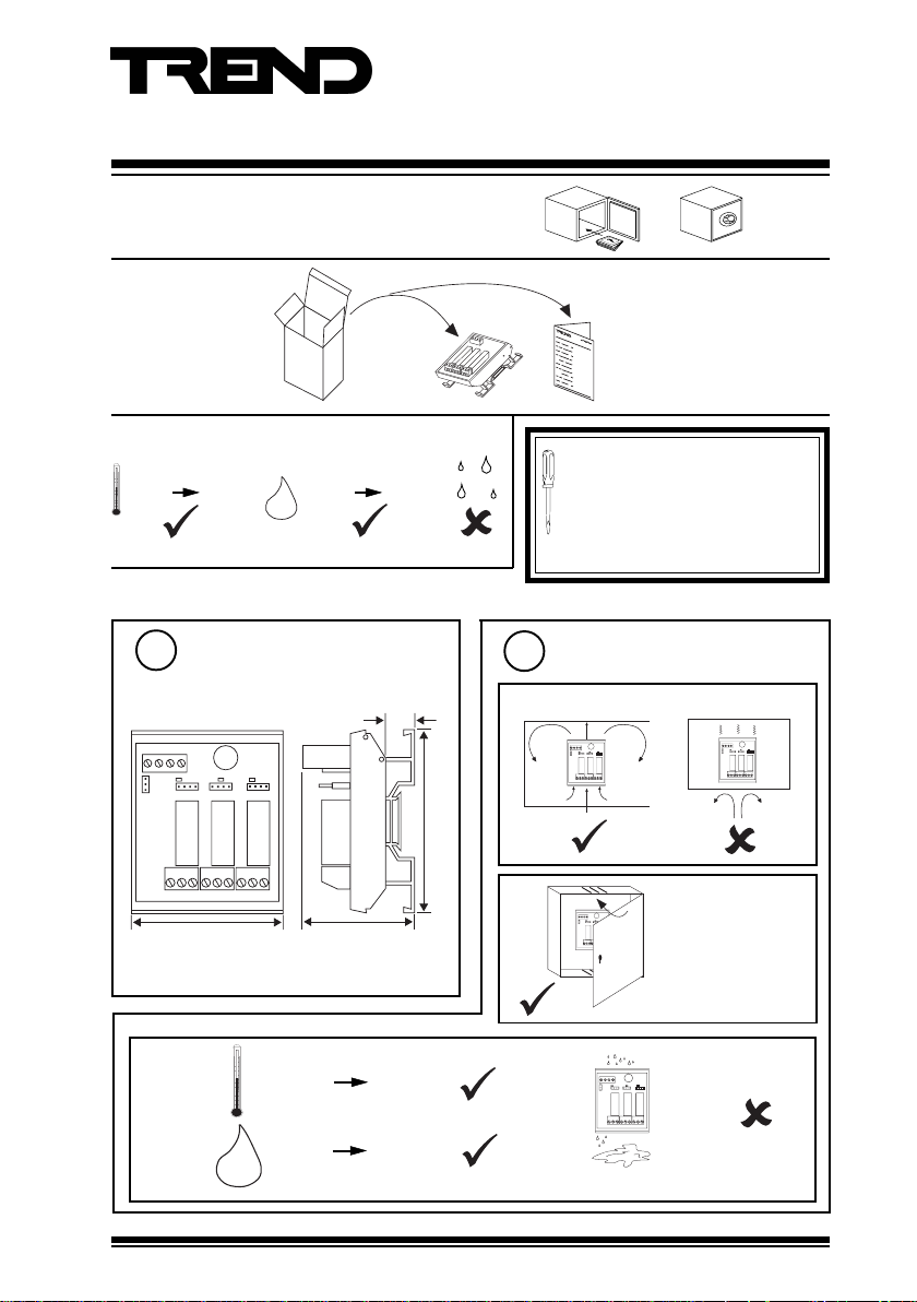
1 UNPACKING
Installation Instructions
3RM/24VAC
3RM/24VAC Installation
Instructions TG200647
2 STORING
It is recommended that the installation
-10 °C
(14 °F)
+70 °C
(158 °F)
H O
2
0 %RH
95 %RH
should comply with the HSE
Memorandum of Guidance on Electricity
at Work Regulations 1989.
For USA Install equipment in
accordance with National Electric Code.
3 INSTALLATION
Dimensions
1
13 mm
(0.51”)
IN 0V 24V
H
T
J1
RL1
FAN/LOW
NONC C NONC C
J2
RL2
COOL/MID
AUTO ON OFF AUTO ON OFF
68 mm (2.68”)
AUTO ON OFF
RL3
HEAT/HIGH
NONC C
J3
83 mm (3.23”)
48 mm (1.89”)
c
-10 °C
(14 °F)
0 %RH 90 %RH
H O
2
3RM/24VAC Three Relay Module (24 Vac/dc) Installation Instructions TG200647 Issue1/C 02/04/07
+50 °C
(122 °F)
2
a
IN
H
T
b
Requirements
0V24V
J1
J2
J3
AUTO ON OFFAUTO ON OFF
AUTO ON OFF
RL3
RL1
RL2
HEAT/HIGH
FAN/LOW
COOL/MID
NONC C NONC C
NONC C
This unit is UL rated
as ‘UL916 listed
accessory to open
energy
management
equipment.’
IN0V 24V
H
J1
T
J2
J3
AUTO ON OFFAUTO ON OFF
AUTO ON OFF
RL3
RL1
RL2
HEAT/HIGH
FAN/LOW
COOL/MID
NONC C NONC C
NONC C
1
3RM/24VAC Installation Instructions
T
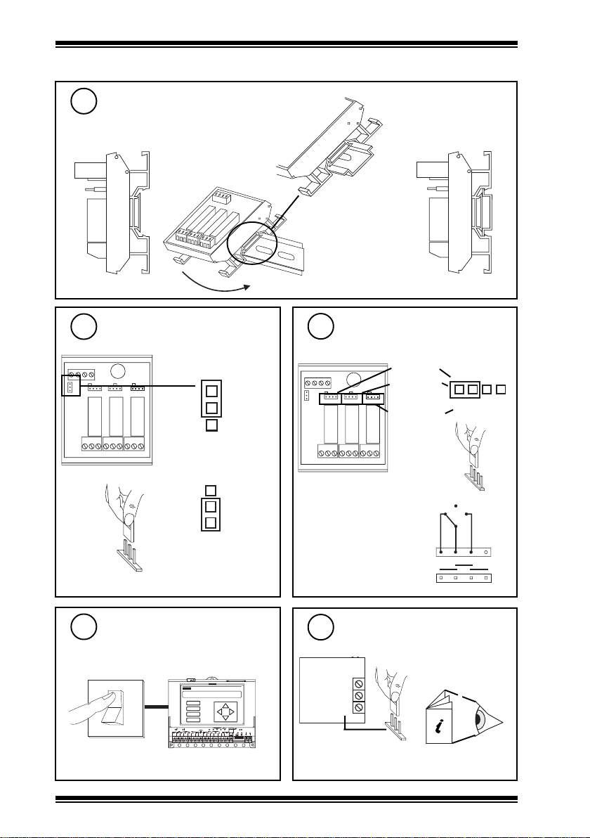
3 INSTALLATION (continued)
Mount on DIN rail
3
0V 24V
IN
H
T
a
Specify Operating Mode
4
J1
J2
AUTO ON OFF AUTO ON OFF
RL1
FAN/LOW
NONC C NONC C
J3
AUTO ON OFF
RL3
RL2
HEAT/HIGH
COOL/MID
NONC C
(or binary switching)
b
Fan/Heat/Cool
HCM
H
T
3 Stage Sequence
TRM
H
Set AUTO/ON/OFF links to
5
AUTO
J2
AUTO ON OFF
RL3
HEAT/HIGH
NONC C
FAN/LOW
COOL/MID
J3
HEAT/HIGH
0V 24V
IN
H
J1
T
AUTO ON OFF AUTO ON OFF
RL1
RL2
FAN/LOW
COOL/MID
NONC C NONC C
Note that each link may be
replaced by a three position
(SPDT) switch which will
normally be centre off; this would
be wired as adjacent diagram
(see note step 15).
c
A U T O
A U T O O N O F F
O F F
A U T O O N
O N
O F F
6
Switch off IQ
Ensure IQ Output channel
7
is Analogue set to Voltage
IQ
O
I
2
A
B
C
D
1
6 7 8
2 3 4 5
3RM/24VAC Three Relay Module (24 Vac/dc) Installation Instructions TG200647 Issue1/C 02/04/07
D P
O K
1 7
2 0
1 8
1 6
1 9
LA N
TX R X
V
24 V
1 1
9 1 0
1 2
1 3
1 5
1 4
12 34 5 67 89 10
IQ
V
24 V
0 V
OUT
V
IQ Controller
Installation Instructions
 Loading...