

Page 1

Biscuit Jointer Set
342
INST/342 v7.1
BISCUIT JOINTER SET
REF. 342
Thank you for purchasing this Trend router
cutter, which should give lasting performance if
used in accordance with these instructions.
The following symbols are used throughout these
instructions.
Denotes risk of personal injury,
This cutter must not be put into service until it
has been established that the power tool to be
connected to this unit is in compliance with
2006/42/EC (identified by the CE marking on
the power tool).
loss of life or damage to the tool
in case of non-observance of the
instructions.
Refer to the instruction manual of
your power tool.
INTENDED USE
This set can be used both in a portable router
or in a fixed position, either mounted overhead
or inverted in a table.
Biscuit jointing is a strong, fast and accurate
way to join hardwoods, softwood, plywood
and composite boards edge to edge and as a
corner joint.
SAFETY
Please read and understand the safety points
at the end of this instruction as well as the
power tool instructions before use.
PLEASE KEEP THESE INSTRUCTIONS IN A
SAFE PLACE.
The attention of UK users is drawn to The
Provision and Use of Work Equipment
Regulations 1998, and any subsequent
amendments.
Users should also read the HSE/HSC Safe
Use of Woodworking Machinery Approved
Code of Practice and Guidance Document
and any amendments.
Users must be competent in using
woodworking equipment before using our
products.
Ensure working position is comfortable and
component is clamped securely.
Please keep children and visitors away from
tools and work area. All tools have a residual
risk, so must therefore be handled with caution.
Attention should be made to the HSE’s Safe
Use of Vertical Spindle Moulding machines
Information Sheet No. 18 and any revisions.
ITEMS REQUIRED
■ Router with suitable collet fitted.
■ Hand tools.
■ Jig making equipment & materials.
■ 11mm A/F spanner.
ITEMS ENCLOSED &
DESCRIPTION OF PARTS
A. Arbor x1
B. Nut 11mm A/F x1
C. Groover 40mm dia. x kerf 4mm x1
D. Ball bearing guide, one of the
following to be fitted:
15mm dia. sleeved x1
19mm dia. x1
23mm dia. sleeved x1
E. Spacer 5.1mm
for 342X1/4TC x1
for 342X1/2TC x3
F. Step washer 1/4” bore x1
G.
3mm spacer
for 342X1/4 & 8MMTC x3
for 342X1/2TC x2
H. Instructions x1
ASSEMBLY
The set is supplied unassembled. Depending
on the biscuit size used, the relevant ball
bearing should be fitted onto the arbor, this
bearing will then automatically set the depth of
groove. Ensure the step washer is fitted in the
recess side of the sleeved ball bearing and the
groover is assembled the correct way round ie,
to match the spindle rotation.
Plan
view of
rotation
Inverted
Overhead
Wherever possible please fit groover on the
spindle towards the shank end. Fitting of
the groover at the nut end will allow thicker
material to be machined, but care must be
taken to avoid excessive side load.
Suggested Biscuit Jointer
set-up for 342X1/2TC
Before using cutter, please ensure it is
correctly assembled and locking nut is fully
tightened to correct torque setting.
PTO
ENVIRONMENTAL PROTECTION
Recycle raw materials instead of disposing
as waste.
Packaging should be sorted for environmentalfriendly recycling.
The product and its accessories at the end
of its life should be sorted for environmentalfriendly recycling.
GUARANTEE
All Trend products are guaranteed against
any defects in either workmanship or material,
except products that have been damaged due
to improper use or maintenance.
© Trend Machinery & Cutting Tools Ltd. 2014 E&OE
® All trademarks acknowledged
Trend Machinery & Cutting Tools Ltd.
Odhams Trading Estate St. Albans Road
Watford WD24 7TR England
Tel: 0044(0)1923 249911
[email protected]
www.trend-uk.com
RECYCLABLE
Page 2
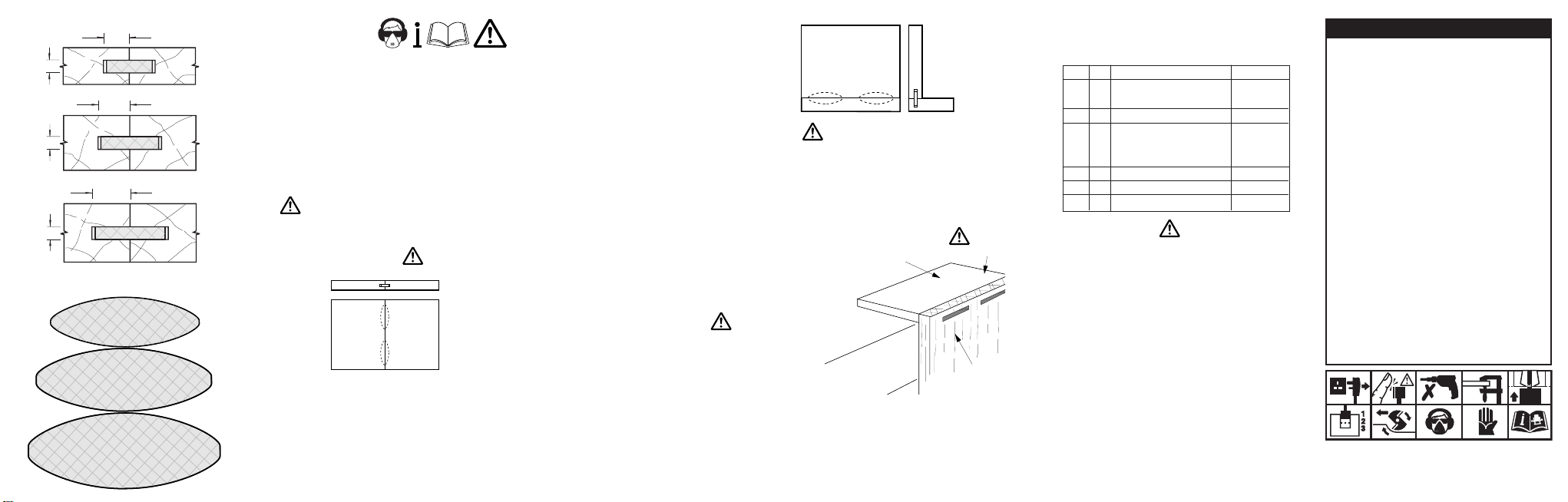
Cross-section of Biscuit Joints
4mm
4mm
4mm
8.5mm
Using bearing B23
10.5mm
Using bearing B19
12.5mm
Using bearing B15
Plan of Biscuits
No. 0 biscuit dimensions:
47.5mm x 15.5mm x 4mm
suitable for 8-12mm board
No. 10 biscuit dimensions:
53mm x 19mm x 4mm
suitable for 13-18mm board
No. 20 biscuit dimensions:
60mm x 23mm x 4mm
suitable for 19mm+ board
OPERATION
Carefully remove the protective wax from the
cutter and dispose.
Insert the cutter shank into the collet at least
all the way to the marked line indicated on the
shank. This ensures at least 3/4 of the shank
length is held in the collet.
Prepare the timber to the required thickness.
Asemble set as instructions using the correct
ball bearing to suit the size of biscuit required.
Ensure nut is tight.
Recommended speed is 24,000 rpm.
Edge to Edge Joints
When biscuit jointing using a hand held router,
the base of the machine is run on the face side
for both joints.
The face sides of both sections of timber
should be marked by pencil where each biscuit
is required. The centres of each biscuit pocket
should be between 150mm to 250mm. The
biscuits should also be no less than 50mm
from the ends of the timber.
The cutter height is set to cut on the centre line
and plunges until the ball bearing touches the
edge of the timber.
Whilst cutting the groove, the router should
be moved forward to make the groove long
enough to insert the biscuit. The finished edge
will have a series of pockets for each biscuit.
A continuous groove can also be routed, but
although quicker to cut, the joint would be
weaker.
Care must be taken not to release the plunge
of the router if the router base aperture is less
than 40mm, as the tooling may be damaged.
When using the biscuit jointing set on a fixed
head router, the same method is used as
before, but a different method of setting the
length of the cut is required. The material
should also be swung into the cutter.
An easy method to judge the pocket length on
an inverted router is to mark the end positions
of the pocket on the top down pressure clamp.
Butt Joint (or Corner Joint)
The edge cut is carried out using the same
methods as mentioned for edge to edge
joints. The face cut is made by clamping the
component on to the edge of a workbench and
butting upto it a piece of waste material. The
top edge of the component must be flush with
the waste material. The waste material will
give better support for the hand router. The
grooving cuts are then carried out as before.
For a butt joint the
groove for the biscuit
is cut into the edge
of one piece of the
component and the
face of the cutter.
As one part of the joint is on the face
of the material, the depth of the groove
should not be too deep so as to weaken
the component, the correct size of biscuit
should be used to take this into account.
Method to Rout Pocket
for Butt Joint
Waste to
support router
bench
Edge of bench
flush
Component to be
grooved on face
Gluing Up
After the grooves are routed, the joint should
be dry cramped to check for fit. A water
based glue (PVA) is used with the biscuit in
the pocket, which will expand as moisture is
absorbed. The boards are simply clamped
together until the glue is dry.
SPARE PARTS
Please use only Trend original spare parts and
accessories.
Item Qty Description Ref. (1 off)
A Arbor 1/2” shank 33/60X1/2
Arbor 1/4” shank 33/60X1/4
C Slotter 40mm x 4.0mm TCT SL/GG
D Bearing 15.0mm dia. B15
Bearing 19.0mm dia. B19
Bearing 23.0mm dia. B23
F Step Washer 1/4” bore BWASH/14
B Replacement arbor nut ANUT/33/60
H Instructions INST/342
MAINTENANCE
Continual satisfactory operation depends upon
proper tool care and regular cleaning.
Cleaning
■ Remove resin build-up regularly.
■ Apply a rust protector to shanks. Do not
use rust protector on ball bearing guides.
Lubrication
■ Use a PTFE dry lubricant spray on tool.
■ Apply a rust protector to shanks. Do not
use rust protector on ball bearing guides.
Storage
Always return cutter to its packaging after use.
Safety Points
1. Disconnect power tool and attachment from power supply when not in
use, before servicing, when making adjustments and when changing
accessories such as cutters. Ensure switch is in “off” position and cutter
has stopped rotating.
2. Read and understand instructions supplied with power tool, attachment
and cutter.
3. Current Personal Protective Equipment (PPE) for eye, ear and
respiratory protection must be worn. Keep hands, hair and clothes
clear of the cutter.
4. Before each use check cutter is sharp and free from damage. Do not
use if cutter is dull, broken or cracked or if any damage is noticeable or
suspected.
5. The maximum speed (nmax) marked on tool or in instructions or on
packaging shall not be exceeded. Where stated, the speed range
should be adhered to.
6. Insert the shank into the router collet at least all the way to the marked
line indicated on the shank. This ensures at least 3/4 of shank length is
held in collet. Ensure clamping surfaces are clean.
7. Check all fixing and fastening nuts, bolts and screws on power tool,
attachment and cutting tools are correctly assembled, tight and to
correct torque setting before use.
8. Ensure all visors, guards and dust extraction is fitted.
9. The direction of routing must always be opposite to the cutter’s
direction of rotation.
10. Do not switch power tool on with the cutter touching the workpiece.
11. Trial cuts should be made in waste material before starting any project.
12. Repair of tools is only allowed according to tool manufacturers
instructions.
13. Do not take deep cuts in one pass, take shallow passes to reduce the
side load applied to the cutter.
Please see www.trend-uk.com/safety for more safety advice.
Our policy of continuous improvements mean that
specifications may change without notice. Trend
Machinery & Cutting Tools Ltd. cannot be held liable
for any material rendered unusable, or for any form of
consequential loss.
 Loading...