

Page 1
Two Single Relays Module
IN0V
24
V
AUTO ON OFFAUTO ON OFF
J1J2
LOW/LOWER
HIGH/RAISE
NONC C NONCC
IN
2
IN0V
24
V
AUTO ON OFFAUTO ON OFF
J1J2
LOW/LOWER
HIGH/RAISE
NONC C NONCC
IN
2
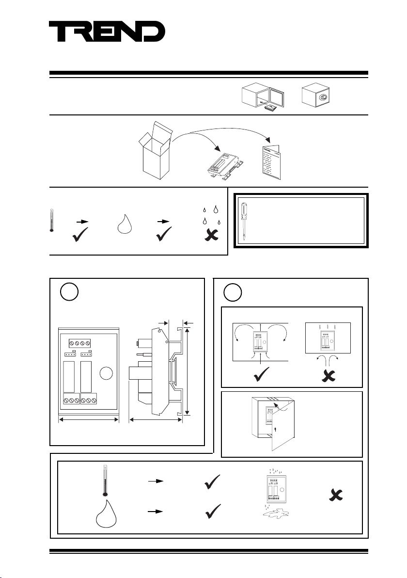
Important: Retain these instructions
1 Unpacking
Installation Instructions
2SRM (24 Vac/dc)
2SRM (24 Vac/dc)
Installation Instruction
TG103210
2 Storage
It is recommended that the installation
-10 °C
(14 °F)
+70 °C
(158 °F)
H O
2
0 %RH
95 %RH
should comply with the HSE
Memorandum of Guidance on Electricity
at Work Regulations 1989.
3 Installation
Dimensions
1
13 mm
(0.51”)
24
IN2IN
0V
V
1
J1J2
AUTO ON OFF AUTO ON OFF
RL1
RL2
LOW/LOWER
HIGH/RAISE
NC NO C NC NO C
57 mm (2.24”)
48 mm (1.89”)
83 mm (3.23”)
c
-10 °C
(14 °F)
0 %RH 90 %RH
H O
2
2SRM (24 Vac/dc) Installation Instructions TG103210 Issue 2 07/07/08
+50 °C
(122 °F)
2
a
b
Requirements
24
IN
0V
IN
V
2
J1J2
AUTO ON OFFAUTO ON OFF
LOW/LOWER
HIGH/RAISE
NONC C NONCC
24
IN
0V
IN
V
2
J1J2
AUTO ON OFFAUTO ON OFF
LOW/LOWER
HIGH/RAISE
NONC C NONC C
1
Page 2
2SRM (24 Vac/dc) Installation Instructions
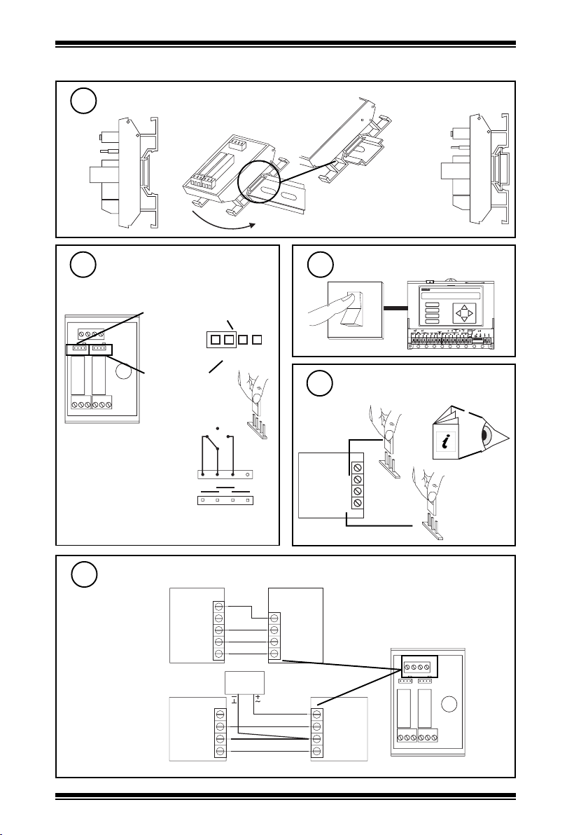
3 Installation (continued)
Mount on DIN rail
3
ab
Set AUTO/ON/OFF links to
4
AUTO
Link for Channel 1
24
IN2IN
0V
V
1
J1J2
AUTO ON OFF AUTO ON OFF
RL1
LOW/LOWER
NC NO C NC NO C
Note that each link may
be replaced by a three
position (SPDT) switch
which will normally be
centre off; this would be
wired as adjacent
diagram (see note
step 13).
(Low/Lower relay)
RL2
Link for Channel 2
(High/Raise relay
HIGH/RAISE
A U T O O N O F F
O F F
A U T O O N
A U T O
O N
O F F
IQ
c
Switch off IQ
5
O
I
1
2 3 4 5
Ensure IQ Output channels
6
are Analogue set to Voltage V
0 V
OUT 2
0 V
OUT 1
V
IQ
A
B
C
D
1 7
1 8
1 6
1 9
V
1 1
6 7 8
9 1 0
1 2
1 3
1 4
IQ Controller
Installation
Instructions
V
D P
O K
2 0
LA N
TX R X
24 V
1 5
12 34 56 78 910
Wire module to controller
7
either using IQ
IQ
24 Vdc Auxiliary
Supply
or using external
24 Vac/dc supply
IQ
24 V
0 V
OUT 2
0 V
OUT 1
PSU
0 V
OUT 2
0 V
OUT 1
maximum current consumed from supply:
24 Vac 73 mA, 24 Vdc 33 mA
2SRM
24 V
IN 2
Terminal size 0.5 to 2.5 mm
(14 to 20 AWG)
0 V
IN 1
24 Vac/dc
24 V
IN 2
0 V
IN 1
2SRM
IN2IN
0V
1
J1J2
AUTO ON OFF AUTO ON OFF
RL1
LOW/LOWER
NC NO C NC NO C
24
V
RL2
HIGH/RAISE
Note that external 24 V supply should be isolated or earthed (grounded) at IQ earth (ground); ensure correct polarity
2
2SRM (24 Vac/dc) Installation Instructions TG103210 Issue 2 07/07/08
2
Page 3

Installation Instructions 2SRM (24 Vac/dc)
3 Installation (continued)
Ensure HVAC Equipment Power
8
Supplies are Switched off
Supply
Supply
HVAC
Equipment
HVAC
Equipment
2SRM
Channel 2
OUT
Channel 1
OUT
O
I
NO
NC
NO
NC
C
C
WARNING: The wires may be connected
to hazardous voltages.
Disconnect power before
attempting any wiring.
Arc suppression
recommended
Relay Output Arc
Suppression Installation
Instructions TG200208
Connect module to HVAC
9
equipment
Contacts rated 5 A max. at 240 Vac single
O
I
phase only (Cosø>=0.4), and 30 Vdc (resistive
load). 2 A for 24 Vdc (inductive load,
T<=30ms).
24
IN2IN
0V
V
1
2
1
AUTO ON OFF AUTO ON OFF
NC NO C NC NO C
2SRM
Channel 2
Channel 1
OUT
OUT
J1J2
RL2
RL1
LOW/LOWER
HIGH/RAISE
Terminal size 0.5 to 2.5 mm
2
(14 to 20 AWG)
Supply
C
NO
NC
C
NO
NC
Supply
HVAC
Equip-
ment
2
HVAC
Equip-
ment
1
10
Close panel
24
IN
IN0V
V
2
J1J2
AUTO ON OFFAUTO ON OFF
LOW/LOWER
HIGH/RAISE
NONC C NONC C
2SRM (24 Vac/dc) Installation Instructions TG103210 Issue 2 07/07/08
11
Switch on IQ
O
I
1
2 3 4 5
IQ
D P
A
B
C
D
6 7 8
O K
1 7
2 0
1 8
1 6
1 9
LA N
TX R X
V
24 V
1 1
9 1 0
1 2
1 3
1 5
1 4
12 34 56 78 910
3
Page 4

2SRM (24 Vac/dc) Installation Instructions
3 Installation (continued)
12
13
Switch on HVAC Equipment Power supplies
Supply
O
I
2SRM
NO
NC
NO
NC
24
IN
IN
C
C
Channel 2
2SRM
HIGH/RAISE
RL1
V
2
J1J2
LOW/LOWER
RL1
0V
1
AUTO ON OFF AUTO ON OFF
Channel 1
Check Relay operation
IQ
A
B
C
D
17
20
18
16
19
V
1
2345
678
9101112
24V
13
15
14
Channel 2
OUT
Channel 1
OUT
DP
OK
LAN
TX RX
12345678910
Supply
NC NO C NC NO C
O
I
HVAC
Equipment
2
HVAC
Equipment
1
Equipment 2
Equipment 1
‘click’
HVAC
HVAC
‘click’
Note that the AUTO/ON/OFF links may be used to test 2SRM to plant installation, however, when
using manual overrides (ON, OFF), feeds switched from other relays on the same module, or
interlocks with other relays may not be operative.
4 Disposal
WEEE Directive :
At the end of their useful life the packaging
and product should be disposed of by a
Do not dispose of with normal household waste.
Do not burn.
Please send any comments about this or any other Trend technical publication to techpubs@trendcontrols.com
© 2008 Honeywell Technologies Sàrl, ECC Divison. All rights reserved. Manufactured for and on behalf of the Environmental and Combustion Controls
Division of Honeywell Technologies Sàrl, Ecublens, Route du Bois 37, Switzerland by its Authorized Representative, Trend Control Systems Ltd.
Trend Control Systems Limited reserves the right to revise this publication from time to time and make changes to the content hereof
without obligation to notify any person of such revisions or changes.
Trend Control Systems Limited
P.O. Box 34, Horsham, West Sussex, RH12 2YF, UK. Tel:+44 (0)1403 21888 Fax:+44 (0)1403 241608 www.trend-controls.com
Trend Control Systems USA
6670 185th Avenue NE, Redmond, Washington 98052, USA. Tel: (425)897-3900, Fax: (425)869-8445 www.trend-controls.com
4
suitable recycling centre.
2SRM (24 Vac/dc) Installation Instructions TG103210 Issue 2 07/07/08
 Loading...