

Page 1

Installation Instructions - Sheet 1
24V
230 VAC
IQLROUTER/230
IQL Lon Router
Important: Retain these instructions
CONTENTS
1.1 Unpacking ............................................. 1-1
1.2 Storage ............................................. 1-1
1 INSTALLATION
1.1 UNPACKING
1.2 STORAGE
-10 °C
(14 °F)
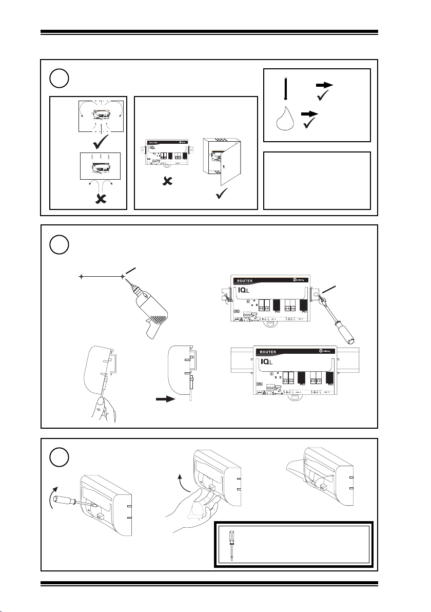
1.3 INSTALLATION - FIXING
!
+50 °C
H O
(122 °F)
Note that this product may involve Lonworks system integration . This procedure should
only be performed by an installer with LonWorks engineering expertise.
2
90 %RH
0
1.3 Installation - Fixing ..................................... 1-1
1.4 Installation - Configuration ......................... 2-1
2 Reset IQLROUTER/230 ................................ 2-2
1
IQLROUTER/230
Installation Instructions
TG200792
1
2
It is recommended that the
installation should comply with
the HSE Memorandum of
Guidance on Electricity at Work
Regulations 1989.
Sheet 1
Sheet 2
Dimensions
1
185 mm (7.28”)
152 mm (5.98”)
89 mm (3.5”)
75 mm (3”)
IQLROUTER/230 Installation Instructions TG200792 Issue 1/A 1/7/04
45 mm
(1.77”)
Requirements
2
a
b
L
OFF
FREE OFF
FREE
BUS
BUS
ON
OFF
11
10
7 8
9
12 13
6
PKT
1 2
3
4
5
LO N - B
LO N - A
A-S VC-B
1 - 1
Page 2
IQLROUTER/230 Installation Instructions - Sheet 1
1.3 INSTALLATION - FIXING (Continued)
Requirements (Continued)
2
c
If not installed well outside normal
d
reach (e.g behind false ceiling)
e
+45 °C
(113 °F)
90 %RH
H O
0 °C
(32 °F)
0
2
Protection: IP20
L
OFF
FREE O FF
FREE
BUS
OFF
FREE OFF
FREE
BUS
BUS
ON
OF F
11
7 8
10
9
12 1 3
6
PK T
1 2
3
4
5
LO N - B
LO N - A
230 VAC
24 V
L
OFF
FREE OFF
FREE
BUS
BUS
ON
OFF
11
8
10
7
9
1213
6
PKT
12
3
4
5
LON - B
LON - A
230VAC
24V
A-SVC- B
A-S VC -B
BUS
ON
OFF
11
10
121 3
78 9
6
PKT
12
3
4
5
LON - B
LON - A
230VAC
24V
A-SVC -B
f
Avoid locations where corrosive
fumes or explosive vapours are
present. Avoid electrical noise
interference.
Mounting
3
Either surface mount
ab
170 mm
(6.69”)
or DIN rail mount
a
2 holes
∅ 6 mm
(0.24”)
b
c
1 - 2
Lift hinged cover
4
a
c
b
WARNING: Failure to use a
screwdriver to open the cover will
cause damage to the unit.
IQLROUTER/230 Installation Instructions TG200792 Issue 1/A 1/7/04
Page 3
Installation Instructions - Sheet 1 IQLROUTER/230
1.3 INSTALLATION - FIXING (Continued)
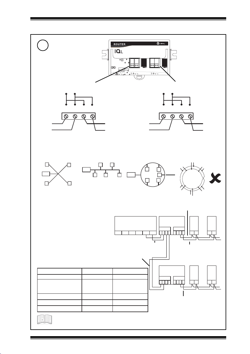
Connect Lon
5
Terminal size 0.5 to 2.55 mm
(14 to 20 AWG)
Network Side A Network Side B
4 5 6 7
L o n A
2
OF F
FR EE OF F
O N
1 2
3
4
5
23 0 V A C
2 4 V
A -S V C -B
BU S
O F F
7 8
9
6
P K T
L O N - A
FR EE
BU S
11
10
12 13
L O N - B
8 9 1 0 1 1L o n B
Lon
Lon
Polarity independent
Lon - FTT (free topology)
Star topology Bus topology Loop topology
T e r m i n a to r
T e r m in a t o r
*
*Terminate Lon bus at one point only
20158nedleB)sdy545(m005)sdy545(m005
dnerT
If used with LPT-10 (powered bus), cable lengths differ - see Link Power Transceiver
User’s Guide (078-0105-01C) available from Echelon
*
Terminate at IQLROUTER using integrated Lon
terminater link A (see step 6).
Integrated Lon terminater link A set to
OFF (see step 6)
elbaChtgnelsubxaMedonotedonxaM
002/FH/61/0/1/PT
)1748nedleB(
GWA22,VIleveLLU)sdy545(m005)sdy034(m004
8.0x2x2Y)tS(YJ)sdy545(m005)sdy053(m023
GWA42,5.taCA865AIT)sdy094(m054)sdy072(m052
(m005)sdy034(m004
*
T e r m i n a t o r
Do not allow wires to cross on a loop
Terminated using integrated Lon terminater link
B (see step 6)
LINC
SCN
LonA
LonB
SCN
LonA
)sdy545
Lon
Lon
Polarity independent
IQL ROUTER
A
LonB
4
3
1
2
IQL ROUTER
A
4
3
1
2
Terminated using integrated Lon
terminater link B (see step 6).
IQL
B
y
4
3
1
2
x
Maximum 64 nodes per
Lon segment
Maximum 40 IQLs (and
LONCs) per virtual Lan
IQL
B
y
4
3
1
2
x
IQL
x
IQL
x
y
y
IQLROUTER/230 Installation Instructions TG200792 Issue 1/A 1/7/04
1 - 3
Page 4

IQLROUTER/230 Installation Instructions - Sheet 1
2 4 V
2 30 V A C
2 4 V
2 30 V A C
1.3 INSTALLATION - FIXING (Continued)
SET Lon Terminator Links
6
OFF
O F F F R E E
O F F F R E E
Terminate Lon bus at one point only
No terminator. Lon must be
terminated elsewhere.
FREE
Use to terminate Lon at
IQL Router
OF F
FR E E OF F
O N
O F F
1 2
P K T
3
4
5
A -S V C - B
BU S
7 8
6
1 0
9
L O N - A
FR E E
BU S
1 1
1 2 1 3
L O N - B
Connect Power
7
DO NOT
Switch on
1
2
2 3 0 V a c
LN3E
230Vac supply
WARNING: This apparatus must be
earthed (via earth terminal).
IQLROUTER/230 consumption = 2VA
Close Hinged Cover
8
Sheet 2
9
2
OF F
FR E E OF F
O N
O F F
1 2
P K T
3
4
5
A -S V C - B
BU S
7 8
6
1 0
9
L O N - A
FR E E
BU S
1 1
1 2 1 3
L O N - B
Clean earths consisting of short (<300 mm,
12”) stranded copper wire (>=1.5 mm2,
16 AWG) to a substantial earthed metal part
(e.g. cable tray) are recommended.
Terminal size 0.5 to 2.5 mm2 (14 to 20 AWG)
ab
IQLROUTER/230 Installation Instructions - Sheet 2
1 - 4
IQLROUTER/230 Installation Instructions TG200792 Issue 1/A 1/7/04
Page 5

Installation Instructions - Sheet 2
O N
O F F
OF F
BU S
FR EE OF F
BU S
FR EE
1 2
3
4
5
P K T
2 4 V
6
7 8
9
10
11
12 13
L O N - A
L O N - B
A -S V C -B
23 0 V A C
O N
O F F
2 4 V
23 0 V A C
IQLROUTER/230
IQL Lon Router
1.4 INSTALLATION - CONFIGURATION
Sheet 1
1
2
IQLROUTER/230 Installation Instructions - Sheet 1
Switch ON
2
Power Supply
Check Router
3
Power
✘
✔
check power
2
IQLROUTER
O
I
Packet
✔
Service
OF F
FR EE OF F
O N
1 2
3
4
5
A -S V C -B
BU S
O F F
7 8
9
6
P K T
L O N - A
FR EE
BU S
11
10
12 13
L O N - B
✔
...
...
✘
Contact Trend
Contact Trend
✘
...
IQLROUTER/230 Installation Instructions TG200792 Issue 1/A 1/7/04
2 - 1
Page 6

IQLROUTER/230 Installation Instructions - Sheet 2
2 4 V
23 0 V A C
2 4 V
23 0 V A C
2 4 V
23 0 V A C
1.4 INSTALLATION - CONFIGURATION (Continued)
Install using LonWorks Network Manager Tool
4
if a binding IQLs to LonMark devices
or b LINCs version <3.23 straddle router.
or c changing Lon Router from Bridge to Learning
Router, Configured Router, or Repeater
O N
1 2
3
4
5
When installing Lon Router in LonWorks tool press service
button when requested for each side of network.
See LonWorks network manager tool manual. See Trend LonWorks
2
Technical Guide (installation and fault finding). LonWorks System
Integrator must have LonWorks engineering expertise.
2 RESET IQLROUTER/230
If the addresses of IQ System devices have been changed it is necessary to reset the IQL
Router to force its routing table to be regenerated. This done by powering the unit OFF, and
then ON.
OF F
FR EE OF F
BU S
O F F
7 8
9
6
P K T
L O N - A
A -S V C -B
FR EE
BU S
11
10
12 13
L O N - B
Switch OFF
1
O N
O F F
OF F
FR EE OF F
O N
1 2
3
4
5
A -S V C -B
BU S
O F F
7 8
9
6
P K T
L O N - A
FR EE
BU S
11
10
12 13
L O N - B
Switch ON
2
O N
O F F
OF F
FR EE OF F
O N
1 2
3
4
5
A -S V C -B
2 - 2
BU S
O F F
7 8
9
6
P K T
L O N - A
FR EE
BU S
11
10
12 13
L O N - B
IQLROUTER/230 Installation Instructions TG200794 Issue 1/A 1/7/04
Page 7

Installation Instructions - Sheet 2 IQLROUTER/230
IQLROUTER/230 Installation Instructions TG200792 Issue 1/A 1/7/04
2 - 3
Page 8

IQLROUTER/230 Installation Instructions - Sheet 2
Trend Control Systems Ltd reserves the right to revise this publication from time to time and make changes to the content hereof
without obligation to notify any person of such revisions or changes.
P.O. Box 34, Horsham, West Sussex, RH12 2YF United Kingdom Website www.trend-controls.com
Fax (UK) +44 (0)1403 241608Fax (International) +44 (0)1403 210982Telephone +44 (0)1403 211888
Registered office, Novar House 24 Queens Road Weybridge Surrey KT13 9UX Registered in England No 1664519Email trendinfo@novar.com
2 - 4
IQLROUTER/230 Installation Instructions TG200792 Issue 1/A 1/7/04
 Loading...