

Page 1
437A15
TR - E - TI - DGB - 0103 - 05 06/21/2016
Installationsanleitung
Installation Guide
Seite 2 - 16
Page 17 - 32
D
GB
Lieferumfang:
_PC-Adapter
_USB-Kabel
_Flachband-Kabel
_Steckernetzteil
_Programmier-Software
Scope of delivery:
_PC adapter
_USB cable
_Flat Ribbon Cable
_Power Supply Unit
_Programming Software
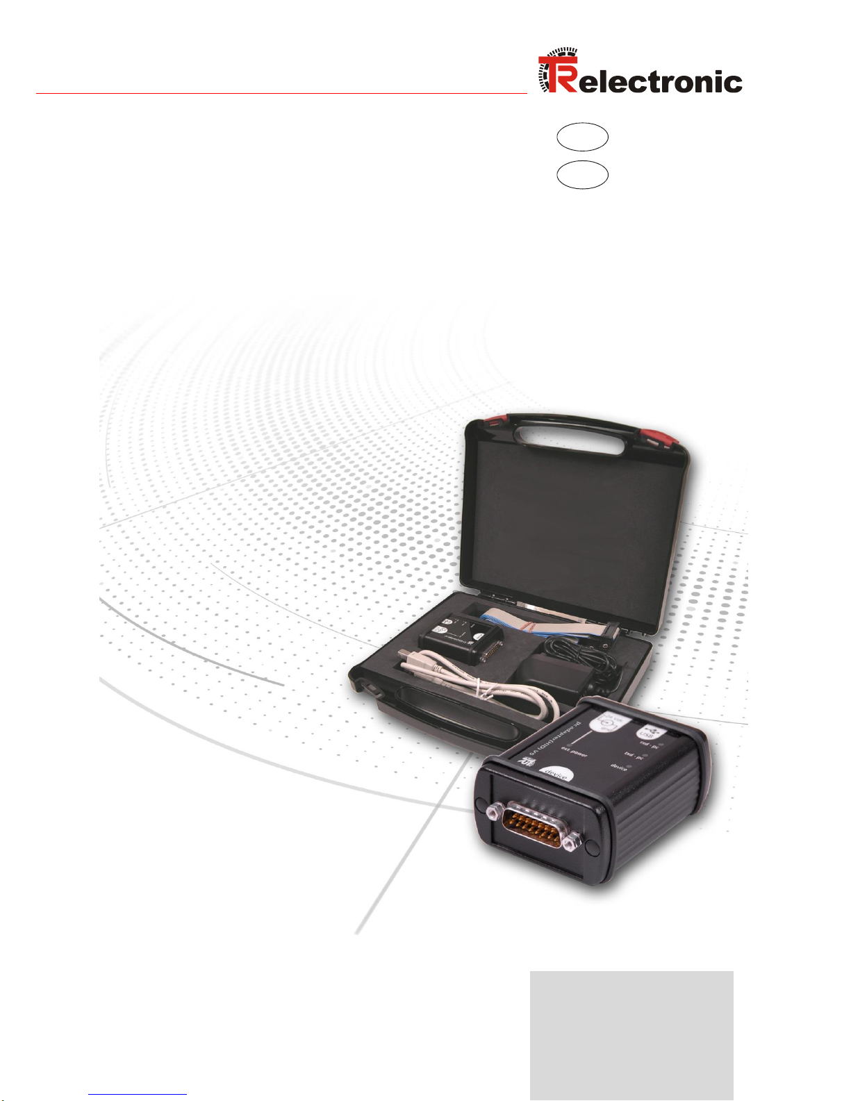
USB PC-Adapter HID V5
Windows® 7/8/10 kompatibel
490-00313 (RS485+CAN)
490-00314 (RS485+SSI)
USB <---> Device
Page 2
TR-Electronic GmbH 2014, All Rights Reserved Printed in the Federal Republic of Germany
Page 2 of 32 TR - E - TI - DGB - 0103 - 05 06/21/2016
TR-Electronic GmbH
D-78647 Trossingen
Eglishalde 6
Tel.: (0049) 07425/228-0
Fax: (0049) 07425/228-33
E-mail: [email protected]
http://www.tr-electronic.de
Urheberrechtsschutz
Dieses Handbuch, einschließlich den darin enthaltenen Abbildungen, ist
urheberrechtlich geschützt. Drittanwendungen dieses Handbuchs, welche von den
urheberrechtlichen Bestimmungen abweichen, sind verboten. Die Reproduktion,
Übersetzung sowie die elektronische und fotografische Archivierung und
Veränderung bedarf der schriftlichen Genehmigung durch den Hersteller.
Zuwiderhandlungen verpflichten zu Schadenersatz.
Änderungsvorbehalt
Jegliche Änderungen, die dem technischen Fortschritt dienen, vorbehalten.
Dokumenteninformation
Ausgabe-/Rev.-Datum: 06/21/2016
Dokument-/Rev.-Nr.: TR - E - TI - DGB - 0103 - 05
Dateiname: TR-E-TI-DGB-0103-05.docx
Verfasser: STB
Schreibweisen
Kursive oder fette Schreibweise steht für den Titel eines Dokuments oder wird zur
Hervorhebung benutzt.
Courier-Schrift zeigt Text an, der auf dem Display bzw. Bildschirm sichtbar ist und
Menüauswahlen von Software.
< > weist auf Tasten der Tastatur Ihres Computers hin (wie etwa <RETURN>).
Marken
Genannte Produkte, Namen und Logos dienen ausschließlich Informationszwecken
und können eingetragene Warenzeichen ihrer jeweiligen Eigentümer sein, ohne dass
eine besondere Kennzeichnung erfolgt.
Page 3

Printed in the Federal Republic of Germany TR-Electronic GmbH 2014, All Rights Reserved
06/21/2016 TR - E - TI - DGB - 0103 - 05 Page 3 of 32
Inhaltsverzeichnis
Inhaltsverzeichnis .............................................................................................................................. 3
Änderungs-Index ................................................................................................................................ 4
1 Allgemeines ..................................................................................................................................... 5
2 Symbol- und Hinweis-Definition .................................................................................................... 5
3 Lieferumfang .................................................................................................................................... 6
4 Hardware-Beschreibung ................................................................................................................. 7
4.1 Hardware-Versionen ............................................................................................................... 7
4.2 Steckerbelegung, 15-pol. SUB-D Stecker .............................................................................. 7
4.2.1 Art.-Nr.: 490-00313 ................................................................................................. 7
4.2.2 Art.-Nr.: 490-00314 ................................................................................................. 7
4.3 Status-LEDs ............................................................................................................................ 8
4.4 Umschaltung der Geräte-Versorgung ..................................................................................... 8
4.5 Abmessungen ......................................................................................................................... 9
5 Programmierung .............................................................................................................................. 10
5.1 Default-Einstellungen .............................................................................................................. 10
5.2 Voraussetzungen .................................................................................................................... 10
5.2.1 Grundeinstellungen ................................................................................................. 11
5.3 Grundparameter ..................................................................................................................... 12
5.3.1 Protokoll-Typ ........................................................................................................... 12
5.3.2 Ausgang Schnittstelle ............................................................................................. 12
5.3.3 Firmware-Update erlaubt ........................................................................................ 12
5.3.4 Hardware-Ausstattung ............................................................................................ 12
5.3.5 Low-Adresse HID-Device ........................................................................................ 12
5.3.6 LJU-Preset .............................................................................................................. 12
5.4 Serielle Schnittstelle ............................................................................................................... 13
5.4.1 Baudrate ................................................................................................................. 13
5.4.2 Freie Baudrate ........................................................................................................ 13
5.4.3 Parity ....................................................................................................................... 13
5.5 SSI .......................................................................................................................................... 14
5.5.1 Anzahl SSI-Bits ....................................................................................................... 14
5.5.2 SSI Code ................................................................................................................. 14
5.5.3 SSI–Frequenz Master-Mode ................................................................................... 14
5.5.4 SSI–Zyklus Master-Mode ........................................................................................ 14
5.5.5 SSI–Takt ................................................................................................................. 15
6 Geräte-Anbindung ........................................................................................................................... 16
Page 4
Änderungs-Index
TR-Electronic GmbH 2014, All Rights Reserved Printed in the Federal Republic of Germany
Page 4 of 32 TR - E - TI - DGB - 0103 - 05 06/21/2016
Änderungs-Index
Änderung
Datum
Index
Erstausgabe
09.12.14
00
Verweis auf Support-DVD entfernt
28.01.15
01
Default-Werte angepasst
25.02.15
02
TRWinProg im Lieferumfang
26.05.15
03
USB PC-Adapter HID V5 RS485+SSI (Art.-Nr.: 490-00314) hinzugefügt
11.06.15
04
Windows 10 kompatibel
21.06.16
05
Page 5

Printed in the Federal Republic of Germany TR-Electronic GmbH 2014, All Rights Reserved
06/21/2016 TR - E - TI - DGB - 0103 - 05 Page 5 of 32
1 Allgemeines
Der USB PC-Adapter HID V5 wird zur Kommunikation zwischen PC – USBSchnittstelle und TR-Geräten benötigt. Die Programmierung des
programmspezifischen Protokolls erfolgt durch die Programmiersoftware „TRWinProg“
ab V5.11, Soft-Nr.: 490-00416.
Es sind keine zusätzlichen Gerätetreiber notwendig, da der PC-Adapter am USB-Port
automatisch als „Standard-HID-Device“ erkannt und eingebunden wird. Es können
maximal 7 PC-Adapter gleichzeitig an einem PC angeschlossen sein.
Systemanforderungen
IBM kompatibler PC
Eine verfügbare USB-Schnittstelle
Betriebssystem Windows® ab Version 98SE
Programmier-Software „TRWinProg“ ab V5.11 (DLL3.1.6) --> Download
2 Symbol- und Hinweis-Definition
bezeichnet wichtige Informationen bzw. Merkmale und Anwendungstipps des verwendeten Produkts.
Page 6
Lieferumfang
TR-Electronic GmbH 2014, All Rights Reserved Printed in the Federal Republic of Germany
Page 6 of 32 TR - E - TI - DGB - 0103 - 05 06/21/2016
3 Lieferumfang
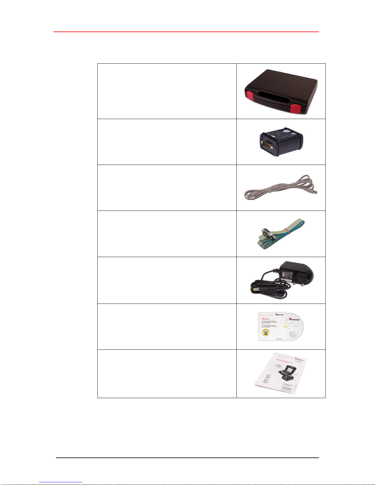
● Kunststoff-Koffer,
mit nachfolgenden Komponenten:
– USB PC-Adapter HID V5
Umsetzung USB <--> Device-Interface
– USB-Kabel 1,00 m
Verbindungskabel zwischen
PC-Adapter und PC
– Flachbandkabel 1,30 m
Verbindungskabel zwischen
PC-Adapter und TR-Schaltschrank-Modul
(15-pol. SUB-D Buchse/Stecker)
– Steckernetzteil 24 V DC, 1A
Versorgungsmöglichkeit des angeschlossenen Gerätes über den PC-Adapter
– Programmiersoftware „TRWinProg“
Soft-Nr.: 490-00416
– Installationsanleitung
TR-E-TI-DGB-0103, Deutsch/Englisch
Page 7
Printed in the Federal Republic of Germany TR-Electronic GmbH 2014, All Rights Reserved
06/21/2016 TR - E - TI - DGB - 0103 - 05 Page 7 of 32
4 Hardware-Beschreibung
4.1 Hardware-Versionen
Artikel-Nummer
unterstützte Schnittstellen
490-00313
RS485+CAN
490-00314
RS485+SSI
4.2 Steckerbelegung, 15-pol. SUB-D Stecker
4.2.1 Art.-Nr.: 490-00313
Pin
Signal
1
RS-485 –
2
RS-485 +
3 – 5
N.C.
6
CAN High
7
intern gebrückt auf Pin 14 (PT Schaltausgang für TA-Mini)
8
CAN Low
9 – 13
N.C.
14
Versorgungsspannung_OUT, 24 V DC
wenn Steckernetzteil am PCAdapter angeschlossen ist
15
Versorgungsspannung_OUT, 0V
4.2.2 Art.-Nr.: 490-00314
Pin
Signal
1
RS-485 – / SSI-Takt –
2
RS-485 + / SSI-Takt +
3 – 6
N.C.
7
intern gebrückt auf Pin 14 (PT Schaltausgang für TA-Mini)
8
N.C.
9
SSI-Daten –
10
SSI-Daten +
11 – 13
N.C.
14
Versorgungsspannung_OUT, 24 V DC
wenn Steckernetzteil am PCAdapter angeschlossen ist
15
Versorgungsspannung_OUT, 0V
Page 8
Hardware-Beschreibung
TR-Electronic GmbH 2014, All Rights Reserved Printed in the Federal Republic of Germany
Page 8 of 32 TR - E - TI - DGB - 0103 - 05 06/21/2016
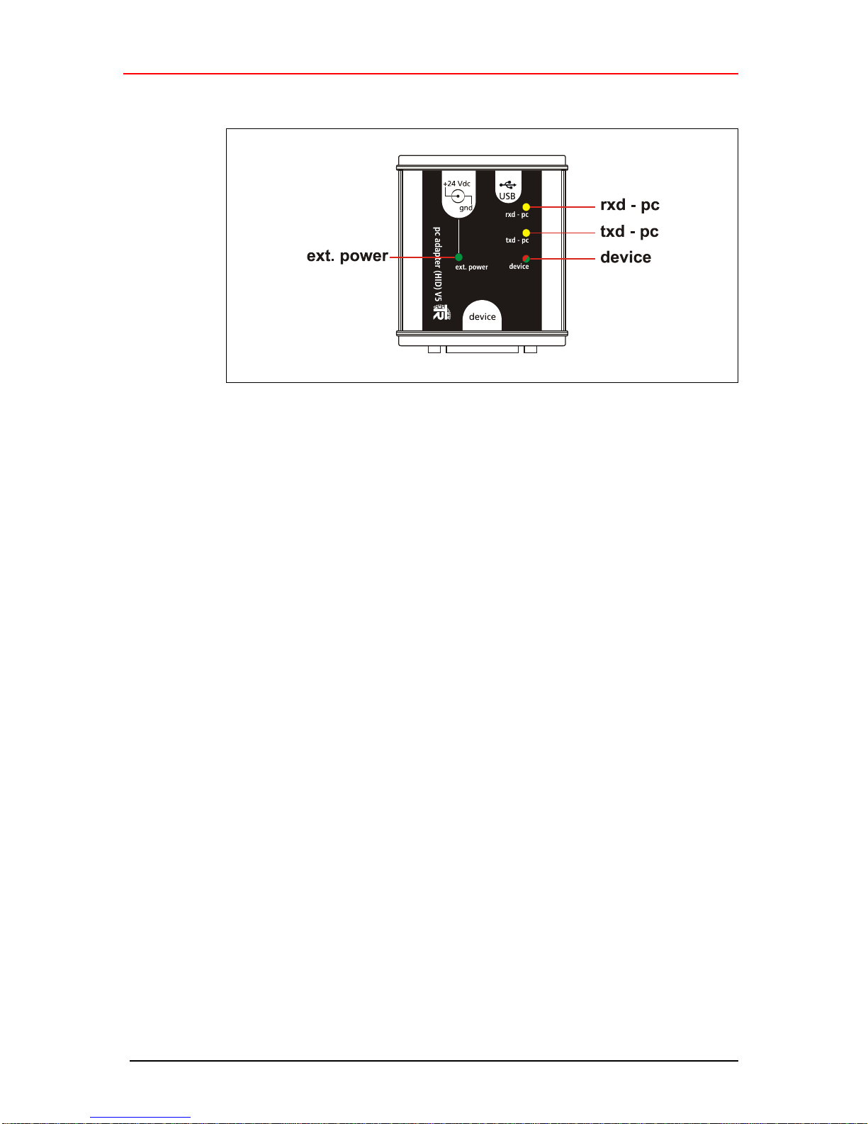
4.3 Status-LEDs
● LED ext. power: leuchtet grün,
wenn das Steckernetzteil am +24 Vdc-Eingang des PC-Adapters angeschlossen
ist. Ein am PC-Adapter angeschlossenes Mess-System kann über den 15-pol.
SUB-D Stecker versorgt werden. Besteht des Weiteren eine USB-Verbindung zu
einem PC mit TRWinProg, wird im Online-Betrieb das angeschlossene MessSystem erkannt. Programmierungen beziehen sich dann auf das Mess-System.
● LED rxd - pc: leuchtet gelb, wenn Daten empfangen werden
● LED txd - pc: leuchtet gelb, wenn Daten gesendet werden
● LED device: leuchtet rot,
wenn eine USB-Verbindung zum PC besteht aber keine Spannungsquelle und
kein Mess-System an den PC-Adapter angeschlossen ist.
● LED device: leuchtet grün,
wenn eine USB-Verbindung zum PC besteht und eine Spannungsquelle oder ein
Mess-System an den PC-Adapter angeschlossen ist.
4.4 Umschaltung der Geräte-Versorgung
● Steckernetzteil nicht am PC-Adapter angeschlossen
- Das Mess-System muss separat mit Spannung versorgt werden.
● Steckernetzteil am PC-Adapter angeschlossen
- Das Mess-System wird über den PC-Adapter mit Spannung versorgt.
Page 9
Printed in the Federal Republic of Germany TR-Electronic GmbH 2014, All Rights Reserved
06/21/2016 TR - E - TI - DGB - 0103 - 05 Page 9 of 32
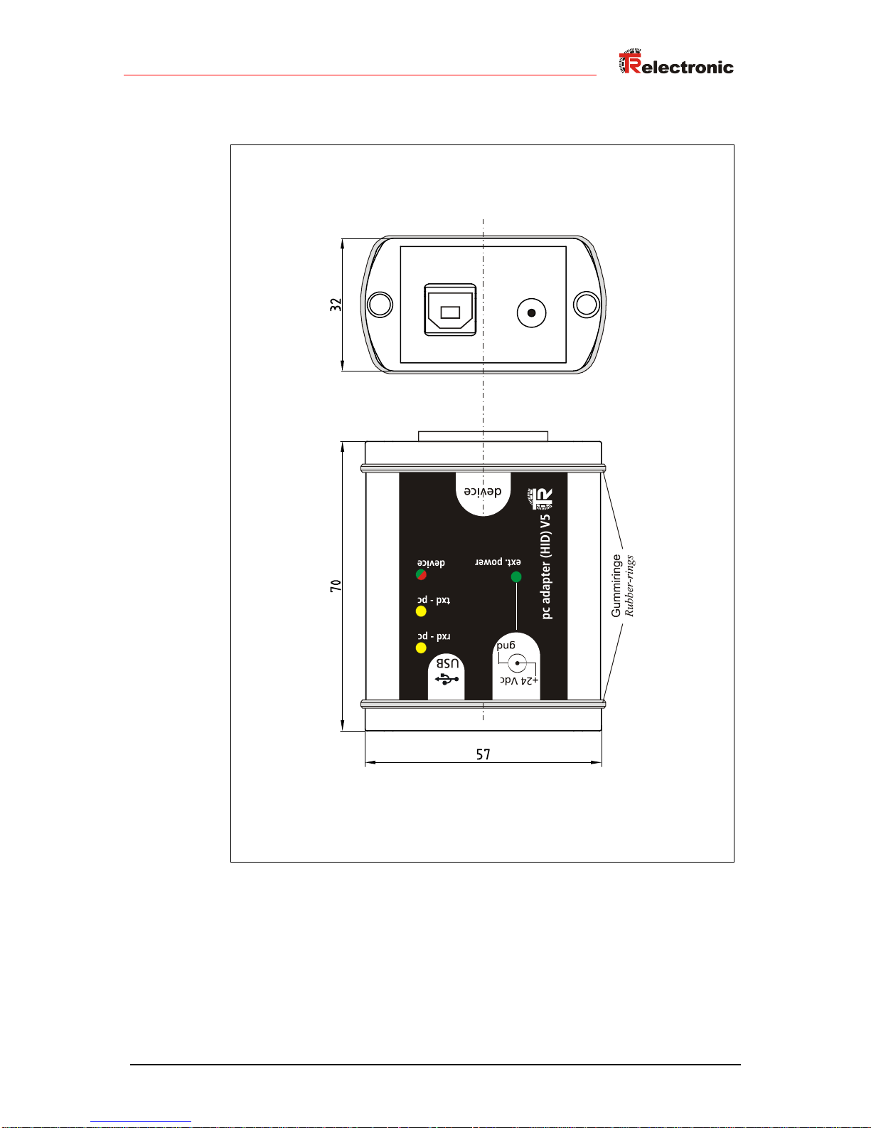
4.5 Abmessungen
Page 10
Programmierung
TR-Electronic GmbH 2014, All Rights Reserved Printed in the Federal Republic of Germany
Page 10 of 32 TR - E - TI - DGB - 0103 - 05 06/21/2016
5 Programmierung
5.1 Default-Einstellungen
Bei Auslieferung sind folgende Parameter voreingestellt:
● Protokoll-Typ: TRWinProg
● Ausgang Schnittstelle: RS485
● Baudrate: 9600 Baud
Wenn der PC-Adapter unter TRWinProg eingesetzt werden soll, muss keine
Programmierung des PC-Adapters vorgenommen werden.
5.2 Voraussetzungen
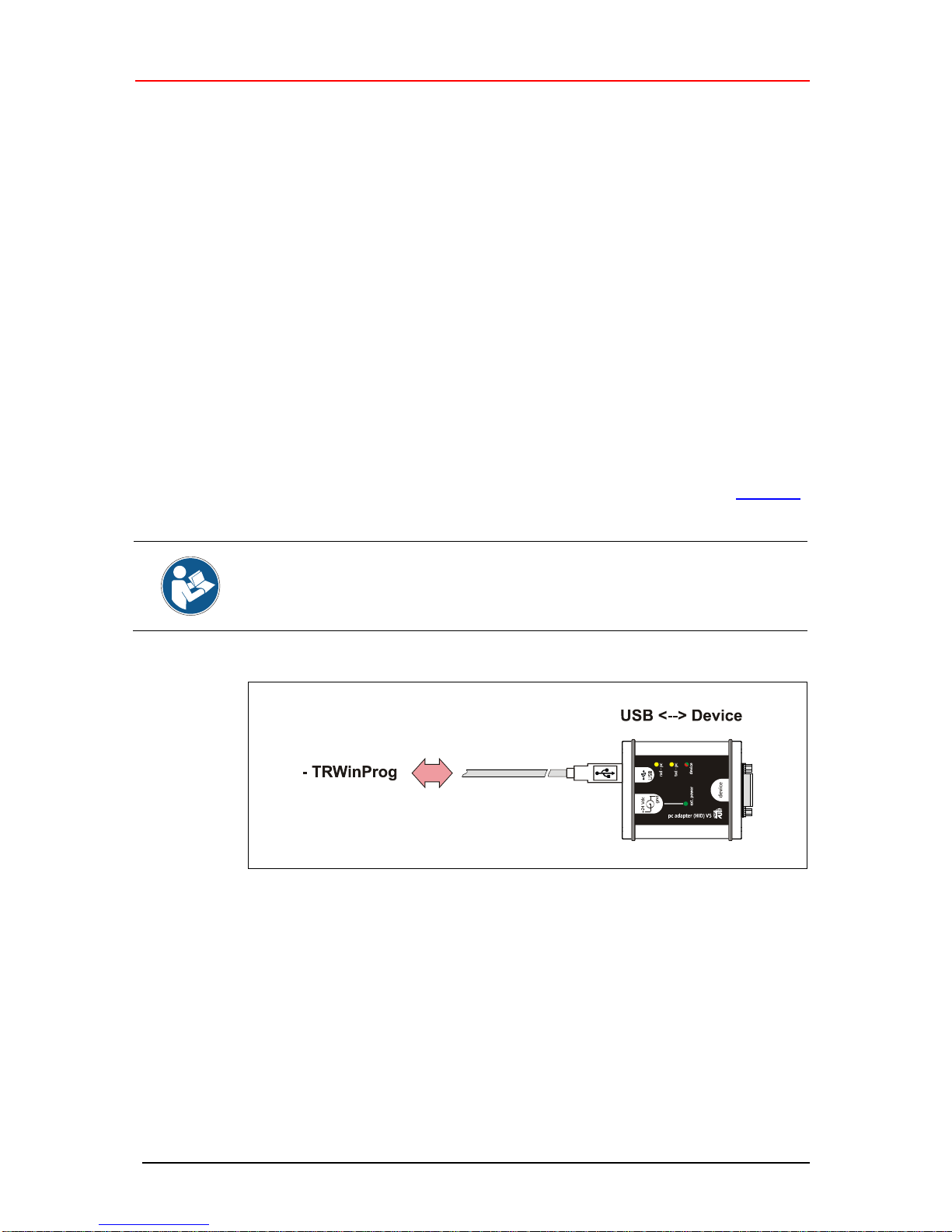
Der PC-Adapter lässt sich nur über die Programmiersoftware TRWinProg ab Version
5.11 (DLL3.1.6) programmieren. Zur Programmierung muss TRWinProg deshalb
bereits auf dem PC installiert sein. Ist dies nicht der Fall, können das Programm und
die Programm-Dokumentation von der Internetseite downgeloadet werden: Download.
Damit der PC-Adapter durch TRWinProg erkannt wird, dürfen kein
Steckernetzteil und kein Mess-System am PC-Adapter angeschlossen sein. Es
darf lediglich eine Verbindung über das USB-Kabel zum PC hergestellt werden!
Page 11
Printed in the Federal Republic of Germany TR-Electronic GmbH 2014, All Rights Reserved
06/21/2016 TR - E - TI - DGB - 0103 - 05 Page 11 of 32
5.2.1 Grundeinstellungen
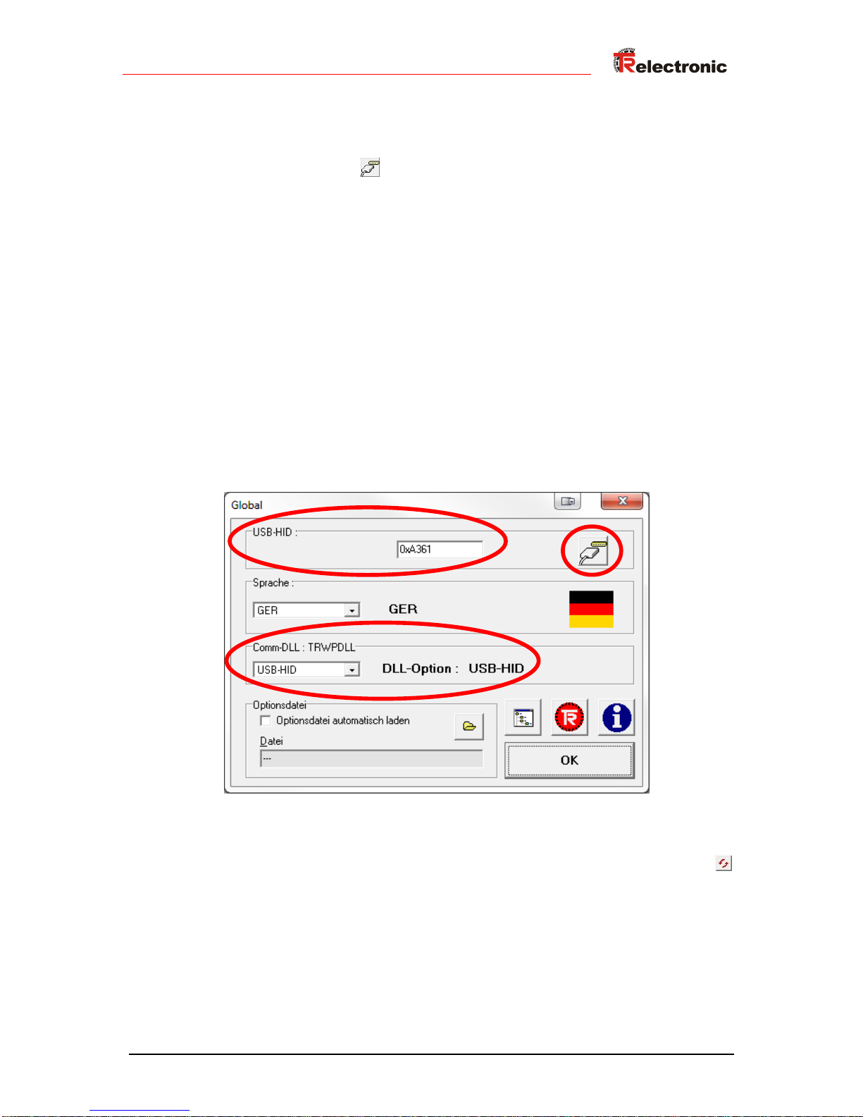
TRWinProg auf dem PC starten und im Menü „Extra --> Global“ auswählen.
Die Schaltfläche rechts im Fenster bei „USB-HID“ anwählen um die
verfügbaren HID-Devices und seriellen Schnittstellen anzuzeigen.
Das gewünschte „HID-Device“ mit einem Doppelklick der linken Maustaste
auswählen. Die HID-Device-Adresse des ausgewählten Mess-System erscheint
dann in der Fensteroberfläche. Sollte das entsprechende HID-Device schon aktiv
sein, kann es nicht erneut gewählt werden. In diesem Fall muss dieses Fenster
geschlossen und gegebenenfalls das Fenster „Global“ erneut geöffnet werden.
Das Drop-Down-Menü unter „Comm-DLL : TRWPDLL“ sollte automatisch auf die
Auswahl „USB-HID“ gesetzt sein.
Unter dem ersten Menüpunkt „USB-HID“ kann ausgewählt werden, auf welches
HID-Device zugegriffen werden soll.
Es dürfen maximal 7 Adapter an einem PC angeschlossen werden. Dafür stehen
die HID-Device-Adressen 0xA361 bis 0xA367 zur Verfügung. Die HID-DviceAdresse kann nachträglich über den Parameter „Low-Adresse HID-Device“
geändert werden, siehe Seite 12.
Um die Einstellungen zu sichern, muss die „OK“-Schaltfläche betätigt werden.
Der PC-Adapter kann nun mittels der „Offline <--> Online“-Schaltfläche
verbunden werden.
Page 12
Programmierung
TR-Electronic GmbH 2014, All Rights Reserved Printed in the Federal Republic of Germany
Page 12 of 32 TR - E - TI - DGB - 0103 - 05 06/21/2016
5.3 Grundparameter
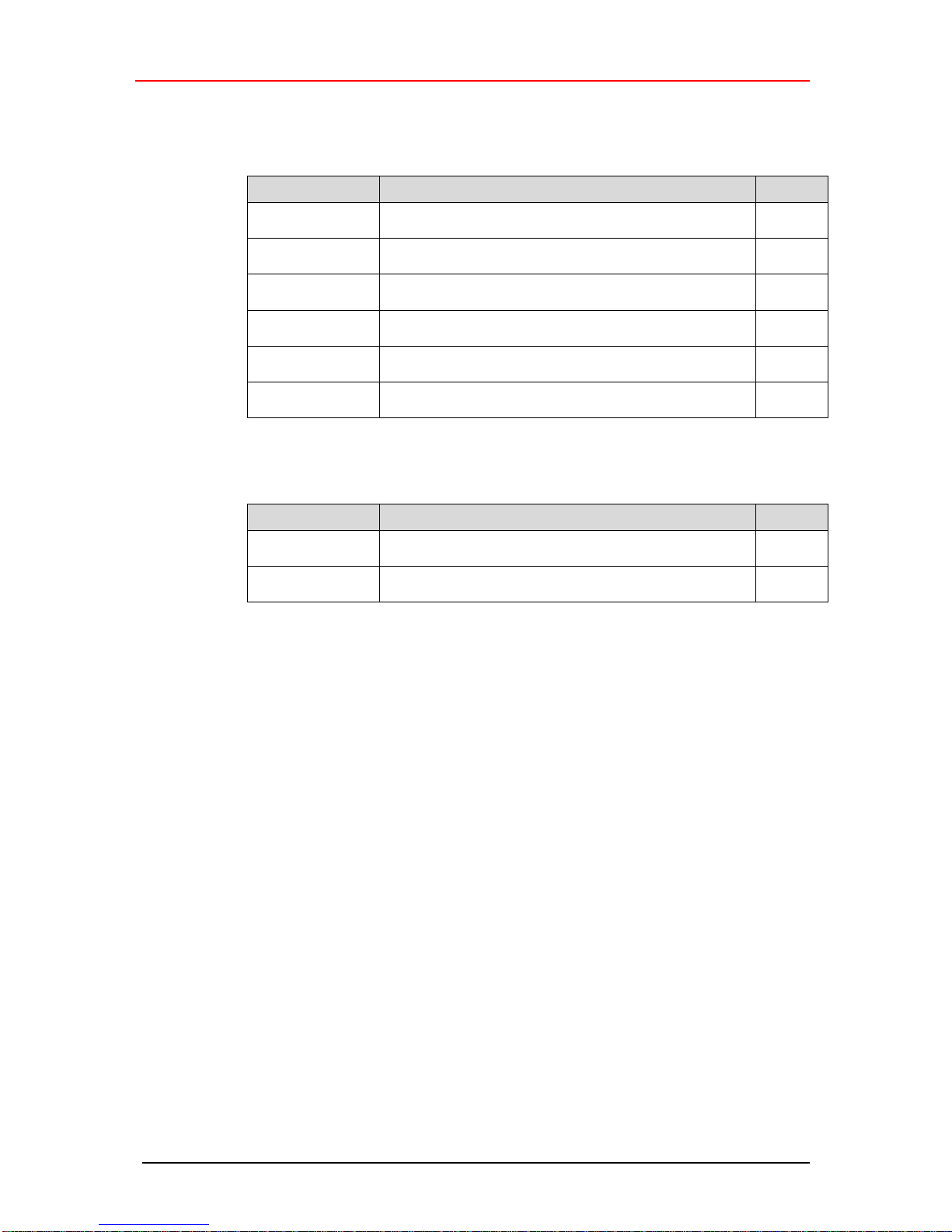
5.3.1 Protokoll-Typ
Auswahl
Beschreibung
Default
TRWinProg
Das zu programmierende Mess-System muss
TRWinProg-kompatibel sein.
X
Serielle
Schnittstelle
Nur für Servicezwecke
Seriell nur
Mithoeren
Für interne Protokollierungen
SSI-Master
Der Adapter kann als Master in einem SSI-Netzwerk
eingesetzt werden.
SSI-Passiv
Der Adapter kann passiv in einem SSI-Netzwerk
eingesetzt werden.
LJU-Protokoll
Das zu programmierende Mess-System muss
LJU-kompatibel sein.
5.3.2 Ausgang Schnittstelle
Auswahl
Beschreibung
Default
RS485
Die Übertragung wird mittels einer RS485-Schnittstelle
realisiert.
X
K-Line oder
CAN-Treiber
Die Übertragung wird mittels einer K-Line- oder CAN
Schnittstelle realisiert.
5.3.3 Firmware-Update erlaubt
Zur Initialisierung eines Firmware-Updates des Adapters können hier die Ziffern
„12345“ eingegeben werden. „0“ bedeutet, dass im Moment kein Firmware-Update
erlaubt ist.
5.3.4 Hardware-Ausstattung
Zeigt an, .welche Schnittstelle von der jeweiligen Adapter-Variante unterstützt wird.
Die einzelnen Hardware-Varianten sind durch unterschiedliche Artikelnummern
gekennzeichnet, siehe „Hardware-Versionen“ auf Seite 7.
5.3.5 Low-Adresse HID-Device
Über dieses Attribut können zur Adapter-Identifizierung die Low-Anteile der HIDDevices-Adressen manuell vergeben werden. Für die am PC angeschlossenen
Adapter steht der Adressbereich von 0x61 bis 0x67 zur Verfügung. Am PC darf jede
Adresse nur einmal vorkommen, daher sind 7 Adapter pro PC möglich.
5.3.6 LJU-Preset
Herstellerspezifische Funktion der LJU-Schnittstelle.
Page 13
Printed in the Federal Republic of Germany TR-Electronic GmbH 2014, All Rights Reserved
06/21/2016 TR - E - TI - DGB - 0103 - 05 Page 13 of 32
5.4 Serielle Schnittstelle
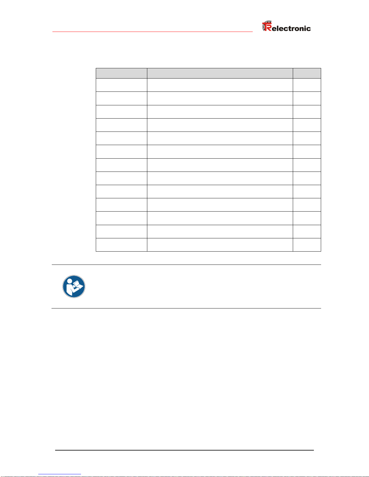
5.4.1 Baudrate
Auswahl
Beschreibung
Default
75 Baud
Übertragungsgeschwindigkeit PC-Adapter <--> PC
75 Bit/s
110 Baud
Übertragungsgeschwindigkeit PC-Adapter <--> PC
110 Bit/s
300 Baud
Übertragungsgeschwindigkeit PC-Adapter <--> PC
300 Bit/s
1200 Baud
Übertragungsgeschwindigkeit PC-Adapter <--> PC
1200 Bit/s
2400 Baud
Übertragungsgeschwindigkeit PC-Adapter <--> PC
2400 Bit/s
4800 Baud
Übertragungsgeschwindigkeit PC-Adapter <--> PC
4800 Bit/s
X
9600 Baud
Übertragungsgeschwindigkeit PC-Adapter <--> PC
9600 Bit/s
19200 Baud
Übertragungsgeschwindigkeit PC-Adapter <--> PC
19200 Bit/s
38400 Baud
Übertragungsgeschwindigkeit PC-Adapter <--> PC
38400 Bit/s
57600 Baud
Übertragungsgeschwindigkeit PC-Adapter <--> PC
57600 Bit/s
62500 Baud
Übertragungsgeschwindigkeit PC-Adapter <--> PC
62500 Bit/s
115200 Baud
Übertragungsgeschwindigkeit PC-Adapter <--> PC
115200 Bit/s
Freie Baudrate
Die Übertragungsgeschwindigkeit PC-Adapter <--> PC
ist im Parameter „Freie Baudrate“ frei wählbar.
Beim Übertragen der Daten an den PC-Adapter wird überprüft, ob die eingestellte
Baudrate durch den ausgewählten Protokoll-Typ auch unterstützt wird. Konflikte
werden über eine entsprechende Fehlermeldung angezeigt.
5.4.2 Freie Baudrate
Wurde bei dem Parameter „Baudrate“ die Auswahl „Freie Baudrate“ getroffen,
kann hier eine frei definierte Übertragungsgeschwindigkeit zwischen 125 Bit/s und
1 000 000 Bit/s eingegeben werden.
5.4.3 Parity
Für Servicezwecke kann über diesen Parameter das Verhalten des Parity-Bits
definiert werden.
Page 14
Programmierung
TR-Electronic GmbH 2014, All Rights Reserved Printed in the Federal Republic of Germany
Page 14 of 32 TR - E - TI - DGB - 0103 - 05 06/21/2016
5.5 SSI
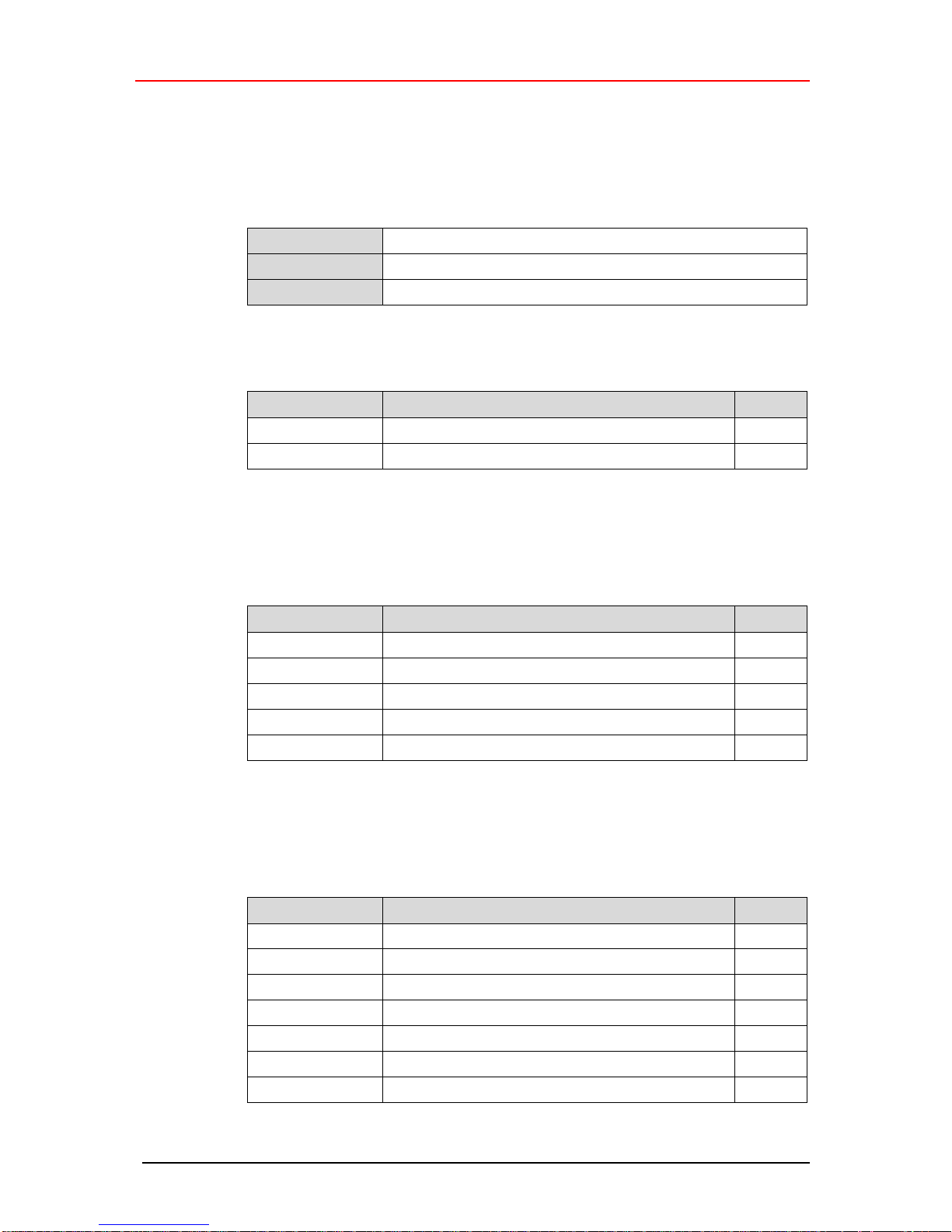
5.5.1 Anzahl SSI-Bits
Der Parameter Anzahl SSI-Bits legt die Anzahl der reservierten Bits für die MessSystem-Position fest.
Untergrenze
12
Obergrenze
31
Default
24
5.5.2 SSI Code
Auswahl
Beschreibung
Default
Binär
SSI-Ausgabecode = Binär
Gray
SSI-Ausgabecode = Gray
X
5.5.3 SSI–Frequenz Master-Mode
Wenn der Adapter als SSI-Master eingesetzt wird, kann mit diesem Parameter die
SSI-Übertragungsgeschwindigkeit festgelegt werden.
Auswahl
Beschreibung
Default
750 kHz
SSI-Übertragungsgeschwindigkeit 750 kHz
400 kHz
SSI-Übertragungsgeschwindigkeit 400 kHz
250 kHz
SSI-Übertragungsgeschwindigkeit 250 kHz
X
200 kHz
SSI-Übertragungsgeschwindigkeit 200 kHz
125 kHz
SSI-Übertragungsgeschwindigkeit 125 kHz
5.5.4 SSI–Zyklus Master-Mode
Wenn der Adapter als SSI-Master eingesetzt wird, kann mit diesem Parameter die
SSI-Zykluszeit festgelegt werden.
Auswahl
Beschreibung
Default
300 s
SSI-Zykluszeit 300 s
400 s
SSI-Zykluszeit 400 s
500 s
SSI-Zykluszeit 500 s
X
1 ms
SSI-Zykluszeit 1 ms
2 ms
SSI-Zykluszeit 2 ms
5 ms
SSI-Zykluszeit 5 ms
10 ms
SSI-Zykluszeit 10 ms
Page 15

Printed in the Federal Republic of Germany TR-Electronic GmbH 2014, All Rights Reserved
06/21/2016 TR - E - TI - DGB - 0103 - 05 Page 15 of 32
5.5.5 SSI–Takt
Mit diesem Parameter kann der SSI-Takt negiert werden.
Auswahl
Beschreibung
Default
normal
SSI-Takt wird nicht negiert
X
negiert
SSI-Takt wird negiert
Page 16
Geräte-Anbindung
TR-Electronic GmbH 2014, All Rights Reserved Printed in the Federal Republic of Germany
Page 16 of 32 TR - E - TI - DGB - 0103 - 05 06/21/2016
6 Geräte-Anbindung
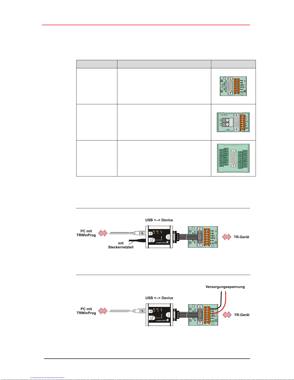
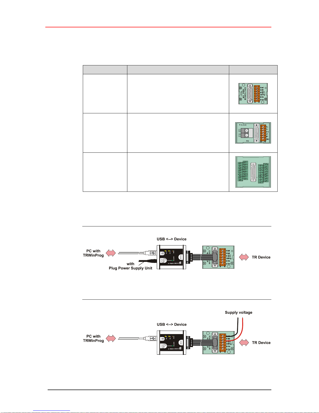
Zur Geräte-Anbindung stehen unterschiedliche Schaltschrankmodule zur Verfügung.
Die 15-pol. SUB-D Buchse dient für den Anschluss des PC-Adapters.
Bestell-Nr.:
Beschreibung
490-00101
PT-6
Standard Schaltschrankmodul mit 6
Schraubklemmen.
490-00107
PT-6N
Schaltschrankmodul mit 6 Schraubklemmen
und Leitungsabschluss der
Programmiersignale.
490-00105
PT-15/2
Schaltschrankmodul mit 2 x 16-pol.
Klemmblöcken
Anschluss-Schema mit Steckernetzteil
Anschluss-Schema ohne Steckernetzteil
Page 17

Printed in the Federal Republic of Germany TR-Electronic GmbH 2014, All Rights Reserved
06/21/2016 TR - E - TI - DGB - 0103 - 05 Page 17 of 32
User Manual
USB PC adapter HID V5
490-00313 (RS485+CAN)
490-00314 (RS485+SSI)
Page 18
TR-Electronic GmbH 2014, All Rights Reserved Printed in the Federal Republic of Germany
Page 18 of 32 TR - E - TI - DGB - 0103 - 05 06/21/2016
TR-Electronic GmbH
D-78647 Trossingen
Eglishalde 6
Tel.: (0049) 07425/228-0
Fax: (0049) 07425/228-33
email: [email protected]
http://www.tr-electronic.de
Copyright protection
This Manual, including the illustrations contained therein, is subject to copyright
protection. Use of this Manual by third parties in contravention of copyright
regulations is not permitted. Reproduction, translation as well as electronic and
photographic archiving and modification require the written content of the
manufacturer. Violations shall be subject to claims for damages.
Subject to modifications
The right to make any changes in the interest of technical progress is reserved.
Document information
Release date / Rev. date: 06/21/2016
Document / Rev. no.: TR - E - TI - DGB - 0103 - 05
File name: TR-E-TI-DGB-0103-05.docx
Author: STB
Font styles
Italic or bold font styles are used for the title of a document or are used for
highlighting.
Courier font displays text, which is visible on the display or screen and software
menu selections.
< > indicates keys on your computer keyboard (such as <RETURN>).
Brand names
Named Products, Names and Logos exclusively serve for information purposes and
can be registered trade marks of their respective owners, without a special marking
within the document.
Page 19

Printed in the Federal Republic of Germany TR-Electronic GmbH 2014, All Rights Reserved
06/21/2016 TR - E - TI - DGB - 0103 - 05 Page 19 of 32
Contents
Contents .............................................................................................................................................. 19
Revision index .................................................................................................................................... 20
1 General information ........................................................................................................................ 21
2 Definition of symbols and instructions ......................................................................................... 21
3 Package contents ............................................................................................................................ 22
4 Hardware description ...................................................................................................................... 23
4.1 Hardware versions .................................................................................................................. 23
4.2 Pin assignment, 15-pol. D-SUB male connector .................................................................... 23
4.2.1 Art.-No.: 490-00313 ................................................................................................ 23
4.2.2 Art.-No.: 490-00314 ................................................................................................ 23
4.3 Status LEDs ............................................................................................................................ 24
4.4 Switch-over the device-supply ................................................................................................ 24
4.5 Dimensions ............................................................................................................................. 25
5 Programming ................................................................................................................................... 26
5.1 Default settings ....................................................................................................................... 26
5.2 Requirements .......................................................................................................................... 26
5.2.1 Basic settings .......................................................................................................... 27
5.3 Basic parameter ...................................................................................................................... 28
5.3.1 Protocol-Type .......................................................................................................... 28
5.3.2 Output Interface ...................................................................................................... 28
5.3.3 Firmware-Update enabled ...................................................................................... 28
5.3.4 Hardware-Interface ................................................................................................. 28
5.3.5 Low-Address HID-Device ........................................................................................ 28
5.3.6 LJU-Preset .............................................................................................................. 28
5.4 Serial Line ............................................................................................................................... 29
5.4.1 Baudrate ................................................................................................................. 29
5.4.2 Free Baudrate ......................................................................................................... 29
5.4.3 Parity ....................................................................................................................... 29
5.5 SSI .......................................................................................................................................... 30
5.5.1 Counts SSI-Bits ....................................................................................................... 30
5.5.2 SSI-Code................................................................................................................. 30
5.5.3 SSI-Frequency Master-Mode .................................................................................. 30
5.5.4 SSI-Cycle Master-mode .......................................................................................... 30
5.5.5 SSI-Clock ................................................................................................................ 31
6 Device connection ........................................................................................................................... 32
Page 20
Revision index
TR-Electronic GmbH 2014, All Rights Reserved Printed in the Federal Republic of Germany
Page 20 of 32 TR - E - TI - DGB - 0103 - 05 06/21/2016
Revision index
Revision
Date
Index
First release
12/09/14
00
Reference to support DVD removed
01/28/15
01
Default values edited
02/25/15
02
TRWinProg to package contents
05/26/15
03
USB PC-Adapter HID V5 RS485+SSI (Art.-No.: 490-00314) added
06/11/15
04
Windows 10 compatible
06/21/16
05
Page 21

Printed in the Federal Republic of Germany TR-Electronic GmbH 2014, All Rights Reserved
06/21/2016 TR - E - TI - DGB - 0103 - 05 Page 21 of 32
1 General information
The USB PC adapter HID V5 is used for communication between PC – USB interface
and TR-devices. The programming of the program-specific protocol occurs with the
programming software “TRWinProg” ex V5.11, Soft-No.: 490-00416.
The PC adapter is detected and integrated automatically as a "standard HID-Device"
at the USB interface. Therefore no additional device drivers are necessary. Maximal 7
PC adapters can be connected to a PC at the same time.
System Requirements
IBM compatible PC
One available USB interface
Operating system Windows® ex version 98SE
Programming software “TRWinProg” ex V5.11 (DLL3.1.6) --> Download
2 Definition of symbols and instructions
indicates important information’s or features and application tips for
the product used.
Page 22
Package contents
TR-Electronic GmbH 2014, All Rights Reserved Printed in the Federal Republic of Germany
Page 22 of 32 TR - E - TI - DGB - 0103 - 05 06/21/2016
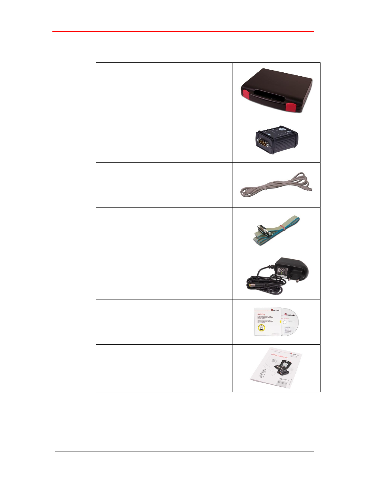
3 Package contents
● Plastic case,
with the following components:
– USB PC adapter HID V5
Conversion USB <--> Device interface
– USB cable 1.00 m
Connection cable between
PC adapter and PC
– Flat ribbon cable 1.30 m
Connection cable between
PC adapter and TR switch cabinet module
(15-pol. SUB-D female/male)
– Plug Power Supply Unit 24 V DC, 1A
The connected device can be supplied via
the PC adapter
– Programming software “TRWinProg”
Soft-No.: 490-00416
– Installation Guide
TR-E-TI-DGB-0103, German/English
Page 23
Printed in the Federal Republic of Germany TR-Electronic GmbH 2014, All Rights Reserved
06/21/2016 TR - E - TI - DGB - 0103 - 05 Page 23 of 32
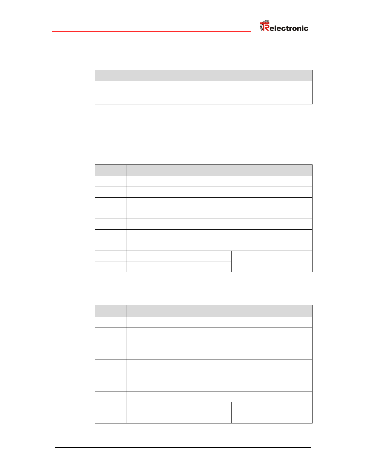
4 Hardware description
4.1 Hardware versions
Art. No.
supported interfaces
490-00313
RS485+CAN
490-00314
RS485+SSI
4.2 Pin assignment, 15-pol. D-SUB male connector
4.2.1 Art.-No.: 490-00313
Pin
Signal
1
RS-485 –
2
RS-485 +
3 – 5
N.C.
6
CAN high
7
internal connected to pin 14 (PT switching output for TA-Mini)
8
CAN low
9 – 13
N.C.
14
Supply voltage_OUT, 24 V DC
if Plug Power Supply Unit is
connected to the PC adapter
15
Supply voltage_OUT, 0V
4.2.2 Art.-No.: 490-00314
Pin
Signal
1
RS-485 – / SSI clock –
2
RS-485 + / SSI clock +
3 – 6
N.C.
7
internal connected to pin 14 (PT switching output for TA-Mini)
8
N.C.
9
SSI data –
10
SSI data +
11 – 13
N.C.
14
Supply voltage_OUT, 24 V DC
if Plug Power Supply Unit is
connected to the PC adapter
15
Supply voltage_OUT, 0V
Page 24
Hardware description
TR-Electronic GmbH 2014, All Rights Reserved Printed in the Federal Republic of Germany
Page 24 of 32 TR - E - TI - DGB - 0103 - 05 06/21/2016
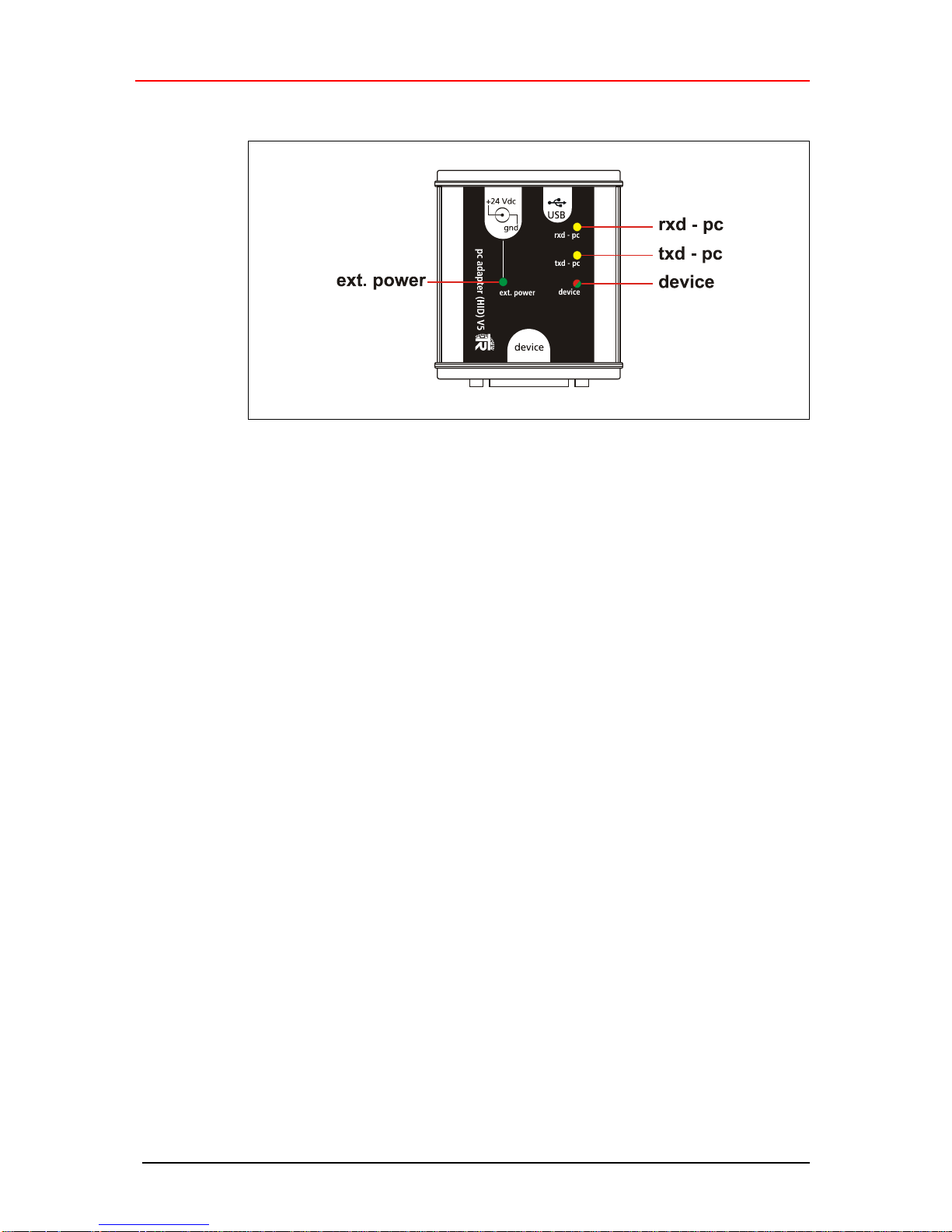
4.3 Status LEDs
● LED ext. power: lights up green,
if the Plug Power Supply Unit is connected at the +24 Vdc input of the PC adapter.
A measuring system which is connected to the PC adapter can be supplied over
the 15-pol. D-SUB connector. If furthermore a connection to a PC with TRWinProg
is established, in online operation the connected measuring system is detected.
Programming’s refer to the measuring system.
● LED rxd - pc: lights up yellow, if data are received
● LED txd - pc: lights up yellow, if data are sent
● LED device: lights up red,
if a USB connection to the PC is established but no power supply and no
measuring system is connected to the adapter.
● LED device: lights up green,
if a USB connection to the PC is established and a power supply or a measuring
system is connected to the adapter.
4.4 Switch-over the device-supply
● Plug Power Supply Unit not connected to the PC
- The measuring system must be supplied separately with voltage.
● Plug Power Supply Unit connected to the PC adapter
- The measuring system is supplied via the PC adapter with voltage.
Page 25
Printed in the Federal Republic of Germany TR-Electronic GmbH 2014, All Rights Reserved
06/21/2016 TR - E - TI - DGB - 0103 - 05 Page 25 of 32
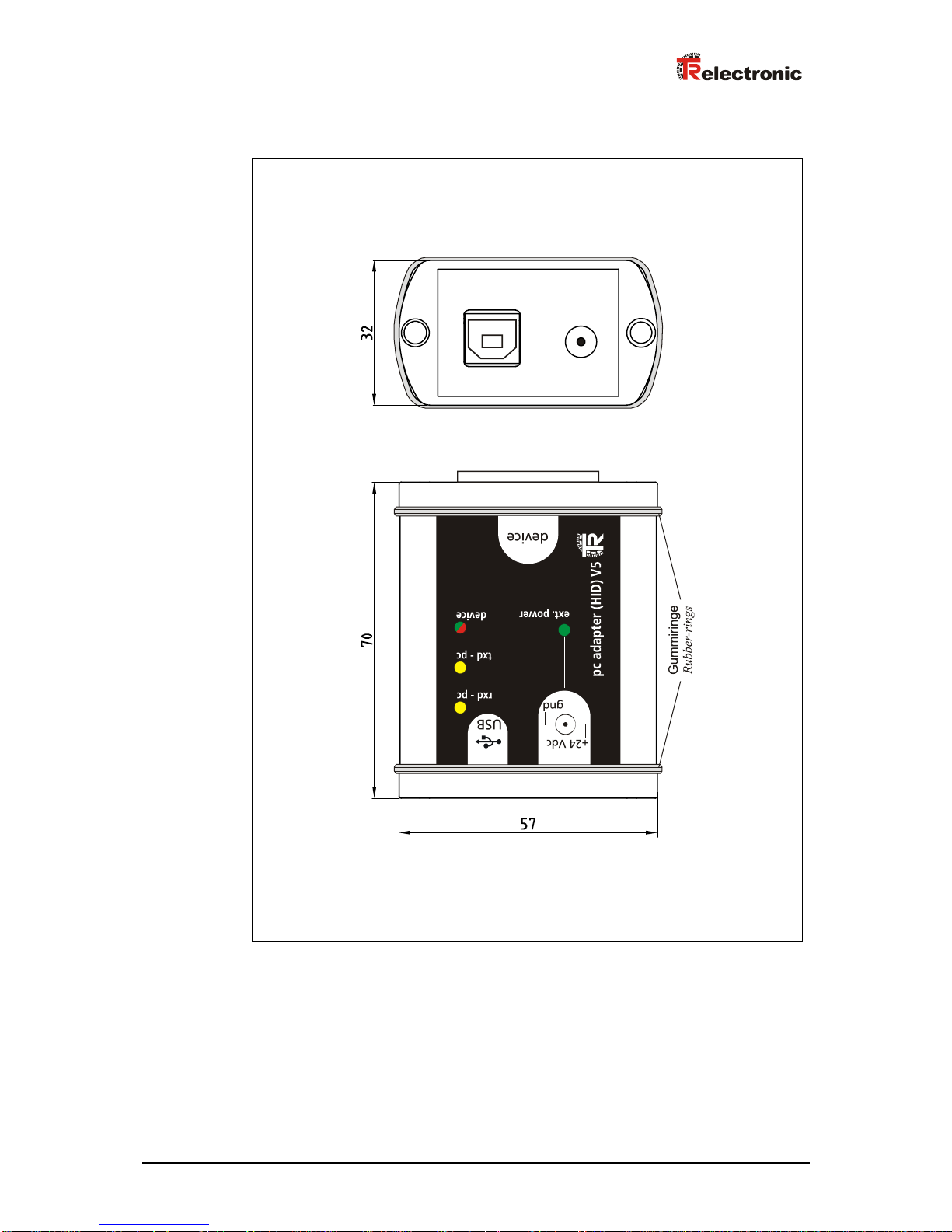
4.5 Dimensions
Page 26
Programming
TR-Electronic GmbH 2014, All Rights Reserved Printed in the Federal Republic of Germany
Page 26 of 32 TR - E - TI - DGB - 0103 - 05 06/21/2016
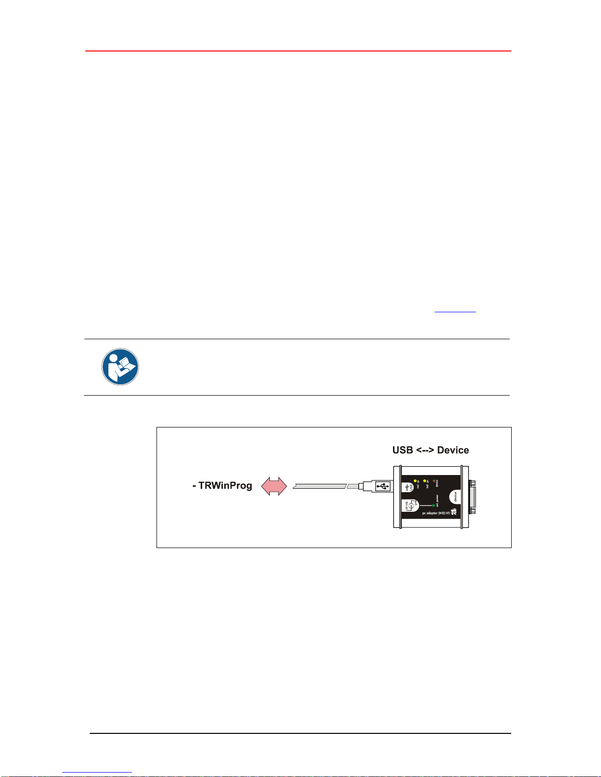
5 Programming
5.1 Default settings
In case of delivery the following parameters are preset:
● Protocol-Type: TRWinProg
● Output Interface RS485
● Baud rate: 9600 Baud
If the PC adapter shall be operated under TRWinProg, no programming of the PC
adapter is necessary.
5.2 Requirements
The PC adapter can be programmed only about the programming software
TRWinProg ex version 5.11 (DLL3.1.6). Therefore, TRWinProg must already be
installed on the PC for programming. If this is not the case, the program and the
program documentation can be downloaded from the internet page: Download.
So that the PC adapter is detected by TRWinProg, no Plug Power Supply Unit
and no measuring system at the PC adapter must be connected. Only a
connection about the USB-cable to the PC must be established!
Page 27
Printed in the Federal Republic of Germany TR-Electronic GmbH 2014, All Rights Reserved
06/21/2016 TR - E - TI - DGB - 0103 - 05 Page 27 of 32
5.2.1 Basic settings
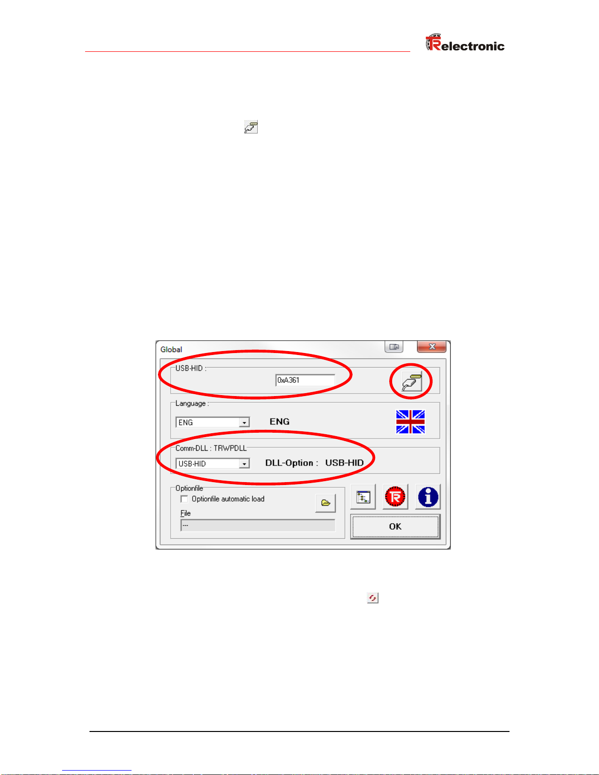
Start TRWinProg on the PC and select the menu “Extra --> Global”.
Select the button right hand in the window at “USB-HID“ to show the available
HID devices and the serial COM ports.
Choose the “HID-Device“ with a double click on the left mouse button. The HID
device address is displayed then in the window. If the depending HID device is
already active, it can’t be selected again. In this case, this window must be closed
and the window “Global” must be opened again.
In the drop-down menu “Comm-DLL : TRWPDLL“, the selection „HID-Device“
must be set automatically.
On top of the window at the menu “USB-HID” it can be selected which HID-device
shall be accessed.
Maximum 7 adapters can be connected at a PC. Therefore the HID device
addresses from 0xA361 to 0xA367 are available. The HID device address can be
changed afterwards about the parameter "Low-Address HID-Device", see page
28.
To save the settings you have to press the „OK“ button.
With the „Offline <--> Online“ button the PC-Adapter now can be
connected.
Page 28
Programming
TR-Electronic GmbH 2014, All Rights Reserved Printed in the Federal Republic of Germany
Page 28 of 32 TR - E - TI - DGB - 0103 - 05 06/21/2016
5.3 Basic parameter
5.3.1 Protocol-Type
Selection
Description
Default
TRWinProg
The measuring system to be programmed must be
TRWinProg compatible.
X
Serial Line
only for service purposes
Serial
only listening
for internal logging
SSI-Master
In a SSI network the adapter can be used as a master.
SSI-Passive
In a SSI network the adapter can be used passively.
LJU-Protocol
The measuring system to be programmed must be LJU
compatible.
5.3.2 Output Interface
Selection
Description
Default
RS485
The transmission is established as RS485 interface.
X
K-Line or
CAN-Driver
The transmission is established as K-Line or CAN
interface.
5.3.3 Firmware-Update enabled
For the initialization of a firmware update of the adapter the numbers "12345" can be
entered here. "0" means that no firmware update is permitted at the moment.
5.3.4 Hardware-Interface
Shows which interfaces are supported by the respective adapter variant. The
hardware variants are indicated by different article numbers, see "Hardware versions"
on page 23.
5.3.5 Low-Address HID-Device
By means of this attribute the low byte of the HID device addresses can be set
manually for adapter identification. For the adapters attached to the PC the address
range from 0x61 to 0x67 is available. At the PC each address can be set only once, 7
adapters per PC are possible therefore.
5.3.6 LJU-Preset
Manufacturer specific function for the LJU interface.
Page 29
Printed in the Federal Republic of Germany TR-Electronic GmbH 2014, All Rights Reserved
06/21/2016 TR - E - TI - DGB - 0103 - 05 Page 29 of 32
5.4 Serial Line
5.4.1 Baudrate
Selection
Description
Default
75 Baud
Transfer rate PC adapter <--> PC: 75 bit/s
110 Baud
Transfer rate PC adapter <--> PC: 110 bit/s
300 Baud
Transfer rate PC adapter <--> PC: 300 bit/s
1200 Baud
Transfer rate PC adapter <--> PC: 1200 bit/s
2400 Baud
Transfer rate PC adapter <--> PC: 2400 bit/s
4800 Baud
Transfer rate PC adapter <--> PC: 4800 bit/s
X
9600 Baud
Transfer rate PC adapter <--> PC: 9600 bit/s
19200 Baud
Transfer rate PC adapter <--> PC: 19200 bit/s
38400 Baud
Transfer rate PC adapter <--> PC: 38400 bit/s
57600 Baud
Transfer rate PC adapter <--> PC: 57600 bit/s
62500 Baud
Transfer rate PC adapter <--> PC: 62500 bit/s
115200 Baud
Transfer rate PC adapter <--> PC: 115200 bit/s
Free Baudrate
The transfer rate PC adapter <--> PC can be freely
selected at the Parameter „Free Baudrate“.
When transferring the data to the PC adapter, it is checked, whether the adjusted
baud rate is also supported by the selected Protocol-Type. Conflicts are displayed
via a corresponding error message.
5.4.2 Free Baudrate
If the selection "free baud rate" was selected at the parameter "Baudrate", a
freely defined transmission rate between 125 bit/s and 1 000 000 bit/s can be set.
5.4.3 Parity
For service purposes the behavior of the Parity bit can be defined about this
parameter.
Page 30
Programming
TR-Electronic GmbH 2014, All Rights Reserved Printed in the Federal Republic of Germany
Page 30 of 32 TR - E - TI - DGB - 0103 - 05 06/21/2016
5.5 SSI
5.5.1 Counts SSI-Bits
The parameter Number of data bits defines the number of reserved bits for the
measuring system position.
lower limit
12
upper limit
31
default
24
5.5.2 SSI-Code
Selection
Description
Default
Binary
SSI output code = Binary
Gray
SSI output code = Gray
X
5.5.3 SSI-Frequency Master-Mode
If the adapter is used as SSI master, with this parameter the SSI transfer rate can be
set.
Selection
Description
Default
750 kHz
SSI transfer rate 750 kHz
400 kHz
SSI transfer rate 400 kHz
250 kHz
SSI transfer rate 250 kHz
X
200 kHz
SSI transfer rate 200 kHz
125 kHz
SSI transfer rate 125 kHz
5.5.4 SSI-Cycle Master-mode
If the adapter is used as SSI master, with this parameter the SSI cycle time can be
set.
Selection
Description
Default
300 s
SSI cycle time 300 s
400 s
SSI cycle time 400 s
500 s
SSI cycle time 500 s
X
1 ms
SSI cycle time 1 ms
2 ms
SSI cycle time 2 ms
5 ms
SSI cycle time 5 ms
10 ms
SSI cycle time 10 ms
Page 31

Printed in the Federal Republic of Germany TR-Electronic GmbH 2014, All Rights Reserved
06/21/2016 TR - E - TI - DGB - 0103 - 05 Page 31 of 32
5.5.5 SSI-Clock
With this parameter the SSI clock can be negated.
Selection
Description
Default
normal
SSI colck is not negated
X
negated
SSI clock is negated
Page 32
Device connection
TR-Electronic GmbH 2014, All Rights Reserved Printed in the Federal Republic of Germany
Page 32 of 32 TR - E - TI - DGB - 0103 - 05 06/21/2016
6 Device connection
For device connection different switch cabinet modules are available. The 15-pol. DSUB female connector serves for the connection of the PC adapter.
Order-No.:
Description
490-00101
PT-6
Standard switch cabinet module with 6
screw terminals.
490-00107
PT-6N
Switch cabinet module with 6 screw
terminals and line termination of the
programming signals.
490-00105
PT-15/2
Switch cabinet module with 2 x 16-pol.
terminal blocks
Connection schematic with Plug Power Supply Unit
Connection schematic without Plug Power Supply Unit
 Loading...