

TR - ECE - BA - DGB - 0128 - 01 11/20/2018
Benutzerhandbuch
User Manual
Seite 2 - 64
Page 65 - 127
D
GB
_Zusätzliche Sicherheitshinweise
_Installation
_Inbetriebnahme
_Parametrierung
_Fehlerursachen und Abhilfen
_Additional safety instructions
_Installation
_Commissioning
_Parameterization
_Cause of faults and remedies
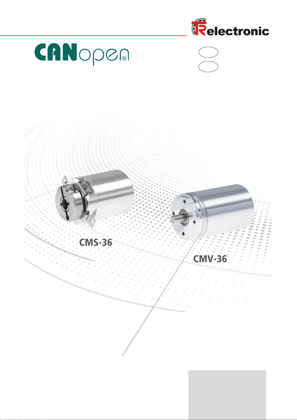
CMV-36
Absolute Encoder CM_-36
CMS-36
437A16_101

Urheberrechtsschutz
Dieses Handbuch, einschließlich den darin enthaltenen Abbildungen, ist
urheberrechtlich geschützt. Drittanwendungen dieses Handbuchs, welche von den
urheberrechtlichen Bestimmungen abweichen, sind verboten. Die Reproduktion,
Übersetzung sowie die elektronische und fotografische Archivierung und
Veränderung bedarf der schriftlichen Genehmigung durch den Hersteller.
Zuwiderhandlungen verpflichten zu Schadenersatz.
Änderungsvorbehalt
Jegliche Änderungen, die dem technischen Fortschritt dienen, vorbehalten.
Dokumenteninformation
Ausgabe-/Rev.-Datum: 11/20/2018
Dokument-/Rev.-Nr.: TR - ECE - BA - DGB - 0128 - 01
Dateiname: TR-ECE-BA-DGB-0128-01.docx
Verfasser: STB
Schreibweisen
Kursive oder fette Schreibweise steht für den Titel eines Dokuments oder wird zur
Hervorhebung benutzt.
Courier-Schrift zeigt Text an, der auf dem Display bzw. Bildschirm sichtbar ist und
Menüauswahlen von Software.
< > weist auf Tasten der Tastatur Ihres Computers hin (wie etwa <RETURN>).
Marken
CANopen und CiA sind eingetragene Gemeinschaftsmarken der CAN in
Automation e.V.
TR-Electronic GmbH
D-78647 Trossingen
Eglishalde 6
Tel.: (0049) 07425/228-0
Fax: (0049) 07425/228-33
E-mail: info@tr-electronic.de
www.tr-electronic.de
TR-Electronic GmbH 2016, All Rights Reserved Printed in the Federal Republic of Germany
Page 2 of 127 TR - ECE - BA - DGB - 0128 - 01 11/20/2018

Inhaltsverzeichnis
Inhaltsverzeichnis .............................................................................................................................. 3
Änderungs-Index ................................................................................................................................ 6
1 Allgemeines ..................................................................................................................................... 7
1.1 Geltungsbereich ...................................................................................................................... 7
1.2 Mitgeltende Dokumente .......................................................................................................... 7
1.3 Referenzen ............................................................................................................................. 8
1.4 Verwendete Abkürzungen / Begriffe ....................................................................................... 9
2 Zusätzliche Sicherheitshinweise ................................................................................................... 10
2.1 Symbol- und Hinweis-Definition .............................................................................................. 10
2.2 Ergänzende Hinweise zur bestimmungsgemäßen Verwendung ............................................ 10
2.3 Organisatorische Maßnahmen ............................................................................................... 11
3 CANopen Informationen ................................................................................................................. 12
3.1 CANopen – Kommunikationsprofil .......................................................................................... 13
3.2 Prozess- und Service-Daten-Objekte ..................................................................................... 14
3.3 Objektverzeichnis (Object Dictionary) .................................................................................... 15
3.4 CANopen Default Identifier, COB-ID ...................................................................................... 15
3.5 Übertragung von SDO Nachrichten ........................................................................................ 16
3.5.1 SDO-Nachrichtenformat .......................................................................................... 16
3.5.2 Lese SDO ............................................................................................................... 18
3.5.3 Schreibe SDO ......................................................................................................... 19
3.6 Netzwerkmanagement, NMT .................................................................................................. 20
3.6.1 Netzwerkmanagement-Dienste .............................................................................. 21
3.6.1.1 NMT-Dienste zur Gerätekontrolle ............................................................................................. 21
3.6.1.2 NMT-Dienste zur Verbindungsüberwachung ............................................................................ 22
3.7 Layer setting services (LSS) und Protokolle ........................................................................... 23
3.7.1 Finite state automaton, FSA ................................................................................... 24
3.7.2 Übertragung von LSS-Diensten .............................................................................. 25
3.7.2.1 LSS-Nachrichtenformat ............................................................................................................. 25
3.7.3 Switch mode Protokolle .......................................................................................... 26
3.7.3.1 Switch state global Protokoll ..................................................................................................... 26
3.7.3.2 Switch state selective Protokoll ................................................................................................. 26
3.7.4 Configuration Protokolle .......................................................................................... 27
3.7.4.1 Configure Node-ID Protokoll ..................................................................................................... 27
3.7.4.2 Configure bit timing parameters Protokoll ................................................................................. 28
3.7.4.3 Activate bit timing parameters Protokoll .................................................................................... 29
3.7.4.4 Store configuration Protokoll ..................................................................................................... 29
3.7.5 Inquire LSS-Address Protokolle .............................................................................. 30
3.7.5.1 Inquire identity Vendor-ID Protokoll .......................................................................................... 30
3.7.5.2 Inquire identity Product-Code Protokoll ..................................................................................... 30
3.7.5.3 Inquire identity Revision-Number Protokoll ............................................................................... 31
3.7.5.4 Inquire identity Serial-Number Protokoll .................................................................................... 31
3.7.6 Inquire Node-ID Protokoll........................................................................................ 32
Printed in the Federal Republic of Germany TR-Electronic GmbH 2016, All Rights Reserved
11/20/2018 TR - ECE - BA - DGB - 0128 - 01 Page 3 of 127

Inhaltsverzeichnis
3.7.7 Identification Protokolle ........................................................................................... 33
3.7.7.1 LSS identify remote slave Protokoll .......................................................................................... 33
3.7.7.2 LSS identify slave Protokoll ....................................................................................................... 33
3.7.7.3 LSS identify non-configured remote slave Protokoll ................................................................. 34
3.7.7.4 LSS identify non-configured slave Protokoll.............................................................................. 34
3.8 Geräteprofil ............................................................................................................................. 35
4 Installation / Inbetriebnahmevorbereitung .................................................................................... 36
4.1 Anschluss ................................................................................................................................ 37
4.2 Bus-Terminierung ................................................................................................................... 37
4.3 Einschalten der Versorgungsspannung .................................................................................. 37
4.4 Einstellen der Node-ID und Baudrate ..................................................................................... 37
4.4.1 Konfiguration der Node-ID, Ablauf .......................................................................... 38
4.4.2 Konfiguration der Baudrate, Ablauf ......................................................................... 38
5 Inbetriebnahme ................................................................................................................................ 39
5.1 CAN – Schnittstelle ................................................................................................................. 39
5.1.1 EDS-Datei ............................................................................................................... 39
6 Kommunikations-Profil ................................................................................................................... 40
6.1 Aufbau der Kommunikationsparameter, 1800h-1801h ........................................................... 40
6.2 Aufbau der Parameter, 1A00h-1A01h .................................................................................... 41
6.3 Übertragungsarten .................................................................................................................. 42
6.3.1 Erstes Sende-Prozessdaten-Objekt (asynchron) ................................................... 42
6.3.2 Zweites Sende-Prozessdaten-Objekt (synchron) ................................................... 42
7 Kommunikationsspezifische Standard-Objekte (CiA DS-301) .................................................... 43
7.1 Objekt 1000h: Gerätetyp ......................................................................................................... 44
7.2 Objekt 1001h: Fehlerregister .................................................................................................. 44
7.3 Objekt 1002h: Hersteller-Status-Register ............................................................................... 44
7.4 Objekt 1003h: Vordefiniertes Fehlerfeld ................................................................................. 45
7.5 Objekt 1005h: COB-ID SYNC Nachricht ................................................................................ 45
7.6 Objekt 1008h: Hersteller Gerätenamen .................................................................................. 46
7.7 Objekt 1009h: Hersteller Hardwareversion ............................................................................. 46
7.8 Objekt 100Ah: Hersteller Softwareversion .............................................................................. 46
7.9 Objekt 100Ch: Guard-Time (Überwachungszeit) ................................................................... 46
7.10 Objekt 100Dh: Life-Time-Faktor (Zeitdauer-Faktor) ............................................................. 46
7.11 Objekt 1010h: Parameter abspeichern ................................................................................. 47
7.12 Objekt 1014h: COB-ID EMCY .............................................................................................. 48
7.13 Objekt 1016h: Consumer Heartbeat Time ............................................................................ 48
7.14 Objekt 1017h: Producer Heartbeat Time .............................................................................. 49
7.15 Objekt 1018h: Identity Objekt ............................................................................................... 49
7.16 Objekt 1021h: EDS abspeichern .......................................................................................... 50
TR-Electronic GmbH 2016, All Rights Reserved Printed in the Federal Republic of Germany
Page 4 of 127 TR - ECE - BA - DGB - 0128 - 01 11/20/2018

7.17 Objekt 1022h: EDS Speicherformat ..................................................................................... 50
7.18 Objekt 1029h: Verhalten im Fehlerfall .................................................................................. 50
7.19 Firmware-Update .................................................................................................................. 50
7.19.1 Objekt 1F50h: Programmdaten ............................................................................ 50
7.19.2 Objekt 1F51h: Programmsteuerung ..................................................................... 51
7.19.3 Objekt 1F56h: Programm Software Identifikation ................................................. 51
7.19.4 Objekt 1F57h: Programm Status .......................................................................... 52
7.20 Objekt 1F80h: NMT Autostart ............................................................................................... 52
8 Parametrierung ................................................................................................................................ 53
8.1 Objekt 2000h: Mode-Umschaltung TR / CiA DS-406 ............................................................. 54
8.2 TR - Mode ............................................................................................................................... 55
8.2.1 Objekt 2001h: TR-Betriebsparameter, Zählrichtung ............................................... 55
8.2.2 Objekt 2100h: TR-COB-ID für Boot-Up Nachricht .................................................. 55
8.2.3 Objekt 2101h: TR-Senden von PDO bei Node-Start .............................................. 55
8.3 CiA DS-406 - Mode ................................................................................................................. 56
8.3.1 Objekt 6000h: Betriebsparameter ........................................................................... 56
8.3.2 Objekt 6003h: Presetwert ....................................................................................... 56
8.3.3 Objekt 6004h: Positionswert ................................................................................... 56
8.3.4 Objekt 6200h: Cyclic-Timer ..................................................................................... 57
8.3.5 Mess-System Diagnose .......................................................................................... 57
8.3.5.1 Objekt 6500h: Betriebsstatus .................................................................................................... 57
8.3.5.2 Objekt 6503h: Alarme ............................................................................................................... 57
8.3.5.3 Objekt 6504h: Unterstützte Alarme ........................................................................................... 57
8.3.5.4 Objekt 6505h: Warnungen ........................................................................................................ 57
8.3.5.5 Objekt 6506h: Unterstützte Warnungen .................................................................................... 58
8.3.5.6 Objekt 6507h: Profil- und Softwareversion ................................................................................ 58
8.3.5.7 Objekt 6508h: Betriebszeit ........................................................................................................ 58
8.3.5.8 Objekt 6509h: Offsetwert .......................................................................................................... 58
8.3.5.9 Objekt 650Ah: Hersteller-Offsetwert ......................................................................................... 58
8.3.5.10 Objekt 650Bh: Serien-Nummer ............................................................................................... 58
9 Emergency-Meldung ....................................................................................................................... 59
10 Übertragung des Mess-System-Positionswertes ....................................................................... 60
11 Fehlerursachen und Abhilfen ....................................................................................................... 61
11.1 SDO-Fehlercodes ................................................................................................................. 61
11.2 Emergency-Fehlercodes ....................................................................................................... 62
11.2.1 Objekt 1001h: Fehlerregister ................................................................................ 62
11.2.2 Objekt 1003h: Vordefiniertes Fehlerfeld, Bits 0 – 15 ............................................ 63
11.3 Sonstige Störungen .............................................................................................................. 63
Printed in the Federal Republic of Germany TR-Electronic GmbH 2016, All Rights Reserved
11/20/2018 TR - ECE - BA - DGB - 0128 - 01 Page 5 of 127

Änderungs-Index
Änderungs-Index
Änderung
Datum
Index
Erstausgabe
15.11.16
00
Hinweis auf Node-ID und Baudrate über TRWinProg
20.11.18
01
TR-Electronic GmbH 2016, All Rights Reserved Printed in the Federal Republic of Germany
Page 6 of 127 TR - ECE - BA - DGB - 0128 - 01 11/20/2018

1 Allgemeines
Das vorliegende Benutzerhandbuch beinhaltet folgende Themen:
Ergänzende Sicherheitshinweise zu den bereits in der Montageanleitung
definierten grundlegenden Sicherheitshinweisen
Installation
Inbetriebnahme
Parametrierung
Fehlerursachen und Abhilfen
Da die Dokumentation modular aufgebaut ist, stellt dieses Benutzerhandbuch eine
Ergänzung zu anderen Dokumentationen wie z.B. Produktdatenblätter,
Maßzeichnungen, Prospekte und der Montageanleitung etc. dar.
Das Benutzerhandbuch kann kundenspezifisch im Lieferumfang enthalten sein, oder
kann auch separat angefordert werden.
1.1 Geltungsbereich
Dieses Benutzerhandbuch gilt ausschließlich für folgende Mess-System-Baureihen mit
CANopen Schnittstelle:
CMV-36
CMS-36
Die Produkte sind durch aufgeklebte Typenschilder gekennzeichnet und sind
Bestandteil einer Anlage.
1.2 Mitgeltende Dokumente
anlagenspezifische Betriebsanleitungen des Betreibers
dieses Benutzerhandbuch
Steckerbelegung
Montageanleitung: www.tr-electronic.de/f/TR-ECE-BA-DGB-0108
Produktdatenblatt: www.tr-electronic.de/s/S011882
Printed in the Federal Republic of Germany TR-Electronic GmbH 2016, All Rights Reserved
11/20/2018 TR - ECE - BA - DGB - 0128 - 01 Page 7 of 127

Allgemeines
1.
ISO 11898: Straßenfahrzeuge, Austausch von Digitalinformation - Controller Area
Network (CAN) für Hochgeschwindigkeits-Kommunikation, November 1993
2.
Robert Bosch GmbH, CAN-Spezifikation 2.0 Teil A und B, September 1991
3.
CiA DS-201 V1.1, CAN im OSI Referenz-Model, Februar 1996
4.
CiA DS-202-1 V1.1, CMS Service Spezifikation, Februar 1996
5.
CiA DS-202-2 V1.1, CMS Protokoll Spezifikation, Februar 1996
6.
CiA DS-202-3 V1.1, CMS Verschlüsselungsregeln, Februar 1996
7.
CiA DS-203-1 V1.1, NMT Service Spezifikation, Februar 1996
8.
CiA DS-203-2 V1.1, NMT Protokoll Spezifikation, Februar 1996
9.
CiA DS-204-1 V1.1, DBT Service Spezifikation, Februar 1996
10.
CiA DS-204-2 V1.1, DBT Protokoll Spezifikation, Februar 1996
11.
CiA DS-206 V1.1, Empfohlene Namenskonventionen für die Schichten,
Februar 1996
12.
CiA DS-207 V1.1, Namenskonventionen der Verarbeitungsschichten,
Februar 1996
13.
CiA DS-301 V3.0, CANopen Kommunikationsprofil auf CAL basierend,
Oktober 1996
14.
CiA DS-305 V2.0, Layer Setting Services (LSS) und Protokolle,
Januar 2006
15.
CiA DS-406 V2.0, CANopen Profil für Encoder, Mai 1998
1.3 Referenzen
TR-Electronic GmbH 2016, All Rights Reserved Printed in the Federal Republic of Germany
Page 8 of 127 TR - ECE - BA - DGB - 0128 - 01 11/20/2018

CMV
Absolut-Encoder mit magnetischer Abtastung, Ausführung mit Vollwelle
CMS
Absolut-Encoder mit magnetischer Abtastung, Ausführung mit Sackloch
EMV
Elektro-Magnetische-Verträglichkeit
CAL
CAN Application Layer. Die Anwendungsschicht für CAN-basierende
Netzwerke ist im
CiA-Draft-Standard 201 ... 207 beschrieben.
CAN
Controller Area Network. Datenstrecken-Schicht-Protokoll für serielle
Kommunikation, beschrieben in der ISO 11898.
CiA
CAN in Automation. Internationale Anwender- und Herstellervereinigung
e.V.: gemeinnützige Vereinigung für das Controller Area Network (CAN).
CMS
CAN-based Message Specification. Eines der Serviceelemente in der
Anwendungsschicht im CAN Referenz-Model.
COB
Communication Object (CAN Message). Übertragungseinheit im CAN
Netzwerk. Daten müssen in einem COB durch das CAN Netzwerk
gesendet werden.
COB-ID
COB-Identifier. Eindeutige Zuordnung des COB. Der Identifier bestimmt
die Priorität des COB´s im Busverkehr.
DBT
Distributor. Eines der Serviceelemente in der Anwendungsschicht im
CAN Referenz-Model. Es liegt in der Verantwortung des DBT´s, COBID´s an die COB´s zu verteilen, die von der CMS benutzt werden.
EDS
Electronic-Data-Sheet (elektronisches Datenblatt)
FSA
Finite state automata. Statusmaschine zur Steuerung von LSS-Diensten
LSS
Layer Setting Services. Dienste und Protokolle für die Konfiguration der
Node-ID und Baudrate über das CAN Netzwerk.
NMT
Network Management. Eines der Serviceelemente in der Anwendungsschicht im CAN Referenz-Model. Führt die Initialisierung,
Konfiguration und Fehlerbehandlung im Busverkehr aus.
PDO
Process Data Object. Objekt für den Datenaustausch zwischen
mehreren Geräten.
SDO
Service Data Object. Punkt zu Punkt Kommunikation mit Zugriff auf die
Objekt-Datenliste eines Gerätes.
1.4 Verwendete Abkürzungen / Begriffe
CAN-spezifisch
Printed in the Federal Republic of Germany TR-Electronic GmbH 2016, All Rights Reserved
11/20/2018 TR - ECE - BA - DGB - 0128 - 01 Page 9 of 127
Zusätzliche Sicherheitshinweise
bedeutet, dass Tod oder schwere Körperverletzung eintreten kann, wenn die entsprechenden Vorsichtsmaßnahmen
nicht getroffen werden.
bedeutet, dass eine leichte Körperverletzung eintreten kann,
wenn die entsprechenden Vorsichtsmaßnahmen nicht
getroffen werden.
bedeutet, dass ein Sachschaden eintreten kann, wenn die
entsprechenden Vorsichtsmaßnahmen nicht getroffen
werden.
bezeichnet wichtige Informationen bzw. Merkmale und
Anwendungstipps des verwendeten Produkts.
Zur bestimmungsgemäßen Verwendung gehört auch:
das Beachten aller Hinweise aus diesem Benutzerhandbuch,
das Beachten der Montageanleitung, insbesondere das dort enthaltene
Kapitel "Grundlegende Sicherheitshinweise" muss vor Arbeitsbeginn
gelesen und verstanden worden sein
2 Zusätzliche Sicherheitshinweise
2.1 Symbol- und Hinweis-Definition
2.2 Ergänzende Hinweise zur bestimmungsgemäßen Verwendung
Das Mess-System ist ausgelegt für den Betrieb an CANopen Netzwerken nach dem
internationalen Standard ISO/DIS 11898 und 11519-1 bis max. 1 MBaud. Das Profil
entspricht dem "CANopen Device Profile für Encoder CiA DS-406 V3.2".
Die technischen Richtlinien zum Aufbau des CANopen Netzwerks der CANNutzerorganisation CiA sind für einen sicheren Betrieb zwingend einzuhalten.
TR-Electronic GmbH 2016, All Rights Reserved Printed in the Federal Republic of Germany
Page 10 of 127 TR - ECE - BA - DGB - 0128 - 01 11/20/2018

2.3 Organisatorische Maßnahmen
Dieses Benutzerhandbuch muss ständig am Einsatzort des Mess-Systems
griffbereit aufbewahrt werden.
Das mit Tätigkeiten am Mess-System beauftragte Personal muss vor Arbeits-
beginn
- die Montageanleitung, insbesondere das Kapitel "Grundlegende
Sicherheitshinweise",
- und dieses Benutzerhandbuch, insbesondere das Kapitel "Zusätzliche
Sicherheitshinweise",
gelesen und verstanden haben.
Dies gilt in besonderem Maße für nur gelegentlich, z.B. bei der
Parametrierung des Mess-Systems, tätig werdendes Personal.
Printed in the Federal Republic of Germany TR-Electronic GmbH 2016, All Rights Reserved
11/20/2018 TR - ECE - BA - DGB - 0128 - 01 Page 11 of 127

CANopen Informationen
3 CANopen Informationen
CANopen wurde von der CiA entwickelt und ist seit Ende 2002 als europäische Norm
EN 50325-4 standardisiert.
CANopen verwendet als Übertragungstechnik die Schichten 1 und 2 des ursprünglich
für den Einsatz im Automobil entwickelten CAN-Standards (ISO 11898-2). Diese
werden in der Automatisierungstechnik durch die Empfehlungen des CiA
Industrieverbandes hinsichtlich der Steckerbelegung, Übertragungsraten erweitert.
Im Bereich der Anwendungsschicht hat CiA den Standard CAL (CAN Application
Layer) hervorgebracht.
Abbildung 1: CANopen eingeordnet im ISO/OSI-Schichtenmodell
Bei CANopen wurde zunächst das Kommunikationsprofil sowie eine "Bauanleitung"
für Geräteprofile entwickelt, in der mit der Struktur des Objektverzeichnisses und den
allgemeinen Kodierungsregeln der gemeinsame Nenner aller Geräteprofile definiert
ist.
TR-Electronic GmbH 2016, All Rights Reserved Printed in the Federal Republic of Germany
Page 12 of 127 TR - ECE - BA - DGB - 0128 - 01 11/20/2018
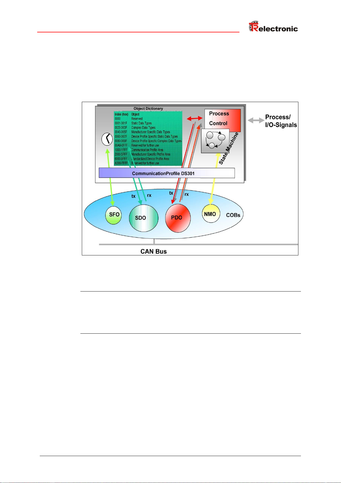
3.1 CANopen – Kommunikationsprofil
Das CANopen Kommunikationsprofil (dokumentiert in CiA DS-301) regelt wie die
Geräte Daten miteinander austauschen. Hierbei werden Echtzeitdaten (z.B.
Positionswert) und Parameterdaten (z.B. Zählrichtung) unterschieden. CANopen
ordnet diesen, vom Charakter her völlig unterschiedlichen Datenarten, jeweils
passende Kommunikationselemente zu.
Abbildung 2: Kommunikationsprofil
Special Function Object (SFO)
- Synchronization (SYNC)
- Emergency (EMCY) Protokoll
Network Management Object (NMO)
z.B.
- Life / Node-Guarding
- Boot-Up,…
- Error Control Protokoll
Printed in the Federal Republic of Germany TR-Electronic GmbH 2016, All Rights Reserved
11/20/2018 TR - ECE - BA - DGB - 0128 - 01 Page 13 of 127

CANopen Informationen
System-Parameter
niederpriore Identifier
Daten auf mehrere
Telegramme verteilt
Daten durch Index
adressiert
bestätigende Dienste
PDO SDO
CiA DS-301 CANopen
Datenarten Kommunikationsprofil
Echtzeitdaten
hochpriore Identifier
max. 8 Bytes
Format vorher vereinbart
CAN pur
keine Bestätigung
3.2 Prozess- und Service-Daten-Objekte
Prozess-Daten-Objekt (PDO)
Prozess-Daten-Objekte managen den Prozessdatenaustausch, z.B. die zyklische
Übertragung des Positionswertes.
Der Prozessdatenaustausch mit den CANopen PDOs ist "CAN pur", also ohne
Protokoll-Overhead. Die Broadcast-Eigenschaften von CAN bleiben voll erhalten. Eine
Nachricht kann von allen Teilnehmern gleichzeitig empfangen und ausgewertet
werden.
Vom Mess-System werden die beiden Sende-Prozess-Daten-Objekte 1800h für
asynchrone (ereignisgesteuert) Positionsübertragung und 1801h für die synchrone
(auf Anforderung) Positionsübertragung verwendet.
Service-Daten-Objekt (SDO)
Service-Daten-Objekte managen den Parameterdatenaustausch, z.B. das azyklische
Ausführen der Presetfunktion.
Für Parameterdaten beliebiger Größe steht mit dem SDO ein leistungsfähiger
Kommunikationsmechanismus zur Verfügung. Hierfür wird zwischen dem
Konfigurationsmaster und den angeschlossenen Geräten ein Servicedatenkanal für
Parameterkommunikation ausgebildet. Die Geräteparameter können mit einem
einzigen Telegramm-Handshake ins Objektverzeichnis der Geräte geschrieben
werden bzw. aus diesem ausgelesen werden.
Wichtige Merkmale von SDO und PDO
TR-Electronic GmbH 2016, All Rights Reserved Printed in the Federal Republic of Germany
Page 14 of 127 TR - ECE - BA - DGB - 0128 - 01 11/20/2018
Abbildung 3: Gegenüberstellung von PDO/SDO-Eigenschaften

COB-Identifier = Funktions-Code + Node-ID
10
0
1 2 3 4 1 2 3 4 5 6 7
Funktions-Code
Node-ID
Objekt
Funktions-Code
COB-ID
Index Kommunikations-Parameter
NMT
0000bin 0 –
SYNC
0001bin
80h
1005
PDO1 (tx)
0011bin
181h – 1FFh
1800h
3.3 Objektverzeichnis (Object Dictionary)
Das Objektverzeichnis strukturiert die Daten eines CANopen- Gerätes in einer
übersichtlichen tabellarischen Anordnung. Es enthält sowohl sämtliche
Geräteparameter als auch alle aktuellen Prozessdaten, die damit auch über das SDO
zugänglich sind.
Abbildung 4: Aufbau des Objektverzeichnisses
3.4 CANopen Default Identifier, COB-ID
CANopen-Geräte können ohne Konfiguration in ein CANopen–Netzwerk eingesetzt
werden. Lediglich die Einstellung einer Busadresse und der Baudrate ist erforderlich.
Aus dieser Knotenadresse leitet sich die Identifierzuordnung für die
Kommunikationskanäle ab.
Beispiele
Printed in the Federal Republic of Germany TR-Electronic GmbH 2016, All Rights Reserved
11/20/2018 TR - ECE - BA - DGB - 0128 - 01 Page 15 of 127

CANopen Informationen
Funktionscode
COB-ID
Bedeutung
11 (1011 bin)
0x580 + Node ID
Slave SDO Client
12 (1100 bin)
0x600 + Node ID
SDO Client Slave
CCD
Index
Subindex
Daten
Byte 0
Byte 1, Low
Byte 2, High
Byte 3
Byte 4
Byte 5
Byte 6
Byte 7
CCD
Bedeutung
Gültig für
0x22
n Byte schreiben
SDO Request
0x23
4 Byte schreiben
SDO Request
0x2B
2 Byte schreiben
SDO Request
0x2F
1 Byte schreiben
SDO Request
0x60
Schreiben erfolgreich
SDO Response
0x80
Fehler
SDO Response
0x40
Leseanforderung
SDO Request
0x43
4 Byte Daten gelesen
SDO Response auf Leseanforderung
0x4B
2 Byte Daten gelesen
SDO Response auf Leseanforderung
0x4F
1 Byte Daten gelesen
SDO Response auf Leseanforderung
3.5 Übertragung von SDO Nachrichten
Die Übertragung von SDO Nachrichten geschieht über das CMS "MultiplexedDomain" Protokoll (CIA DS-202-2).
Mit SDOs können Objekte aus dem Objektverzeichnis gelesen oder geschrieben
werden. Es handelt sich um einen bestätigten Dienst. Der so genannte SDO Client
spezifiziert in seiner Anforderung „Request“ den Parameter, die Zugriffsart
(Lesen/Scheiben) und gegebenenfalls den Wert. Der so genannte SDO Server führt
den Schreib- oder Lesezugriff aus und beantwortet die Anforderung mit einer Antwort
„Response“. Im Fehlerfall gibt ein Fehlercode Auskunft über die Fehlerursache.
Sende-SDO und Empfangs-SDO werden durch ihre Funktionscodes unterschieden.
Das Mess-System (Slave) entspricht dem SDO Server und verwendet folgende
Funktionscodes:
Tabelle 1: COB-IDs für Service Data Object (SDO)
3.5.1 SDO-Nachrichtenformat
Der maximal 8 Byte lange Datenbereich einer CAN-Nachricht wird von einem SDO
wie folgt belegt:
Tabelle 2: SDO-Nachricht
Der Kommando-Code (CCD) identifiziert bei der SDO Request, ob gelesen oder
geschrieben werden soll. Bei einem Schreibauftrag wird zusätzlich die Anzahl der zu
schreibenden Bytes im CCD kodiert.
Bei der SDO Response zeigt der CCD an, ob die Request erfolgreich war. Im Falle
eines Leseauftrags gibt der CCD zusätzlich Auskunft über die Anzahl der gelesenen
Bytes:
Tabelle 3: Kommando-Codes für SDO
Im Fall eines Fehlers (SDO Response CCD = 0x80) enthält der Datenbereich einen
4-Byte-Fehlercode, der über die Fehlerursache Auskunft gibt. Die Bedeutung der
Fehlercodes ist aus der Tabelle 10: SDO-Fehlercodes, Seite 61 zu entnehmen.
TR-Electronic GmbH 2016, All Rights Reserved Printed in the Federal Republic of Germany
Page 16 of 127 TR - ECE - BA - DGB - 0128 - 01 11/20/2018

CCD
Bedeutung
Gültig für
0x40
Leseanforderung, Einleitung
SDO Request
0x41
1 Datensegment vorhanden
Die Anzahl der zu lesenden Bytes steht in den
Bytes 4 bis 7.
SDO Response
CCD
Bedeutung
Gültig für
0x60
Leseanforderung
SDO Request
0x01
Kein weiteres Datensegment vorhanden.
Die Bytes 1 bis 7 beinhalten die angeforderten Daten.
SDO Response
Segment Protokoll, Datensegmentierung
Manche Objekte beinhalten Daten, die größer als 4 Byte sind. Um diese Daten lesen
zu können, muss das „Segment Protokoll“ benutzt werden.
Zunächst wird der Lesevorgang wie ein gewöhnlicher SDO-Dienst mit dem
Kommando-Code = 0x40 eingeleitet. Über die Response wird angezeigt, um wie viele
Datensegmente es sich handelt und wie viele Bytes gelesen werden können. Mit
nachfolgenden Leseanforderungen können dann die einzelnen Datensegmente
gelesen werden. Ein Datensegment besteht jeweils aus 7 Bytes.
Beispiel für das Lesen eines Datensegmentes:
Telegramm 1
Telegramm 2
Printed in the Federal Republic of Germany TR-Electronic GmbH 2016, All Rights Reserved
11/20/2018 TR - ECE - BA - DGB - 0128 - 01 Page 17 of 127

CANopen Informationen
Lese SDO´s
Byte
0 1 2 3 4 5 6
7
Inhalt
Code
Index
Sub-
index
Daten
0
Daten
1
Daten
2
Daten
3 40h
Low
High
Byte 0 0 0 0
Lese SDO´s
Byte
0 1 2 3 4 5 6
7
Inhalt
Code
Index
Sub-
index
Daten
0
Daten
1
Daten
2
Daten
3
4xh
Low
High
Byte
Daten
Daten
Daten
Daten
7 6 5 4 3 2 1
0
0 1 0 0 n
1
1
3.5.2 Lese SDO
„Domain Upload“ einleiten
Anforderungs-Protokoll-Format:
COB-Identifier = 600h + Node-ID
Das „Lese-SDO“ Telegramm muss an den Slave gesendet werden.
Der Slave antwortet mit folgendem Telegramm:
Antwort-Protokoll-Format:
COB-Identifier = 580h + Node-ID
Format-Byte 0:
MSB LSB
n = Anzahl der Datenbytes (Bytes 4-7), welche keine Daten beinhalten.
Wenn nur 1 Datenbyte (Daten 0) Daten enthält, ist der Wert von Byte 0 = "4Fh".
Ist Byte 0 = 80h, wird die Übertragung abgebrochen.
TR-Electronic GmbH 2016, All Rights Reserved Printed in the Federal Republic of Germany
Page 18 of 127 TR - ECE - BA - DGB - 0128 - 01 11/20/2018

Schreibe SDO´s
Byte
0 1 2 3 4 5 6
7
Inhalt
Code
Index
Sub-
index
Daten
0
Daten
1
Daten
2
Daten
3 2xh
Low
High
Byte 0 0 0 0
7 6 5 4 3 2 1
0
0 0 1 0 n
1
1
Lese SDO´s
Byte
0 1 2 3 4 5 6
7
Inhalt
Code
Index
Sub-
index
Daten
0
Daten
1
Daten
2
Daten
3
60h
Low
High
Byte 0 0 0 0
3.5.3 Schreibe SDO
„Domain Download“ einleiten
Anforderungs-Protokoll-Format:
COB-Identifier = 600h + Node-ID
Format-Byte 0:
MSB LSB
n = Anzahl der Datenbytes (Bytes 4-7), welche keine Daten beinhalten.
Wenn nur 1 Datenbyte (Daten 0) Daten enthält, ist der Wert von Byte 0 = "2Fh".
Das „Schreibe-SDO“ Telegramm muss an den Slave gesendet werden.
Der Slave antwortet mit folgendem Telegramm:
Antwort-Protokoll-Format:
COB-Identifier = 580h + Node-ID
Ist Byte 0 = 80h, wird die Übertragung abgebrochen.
Printed in the Federal Republic of Germany TR-Electronic GmbH 2016, All Rights Reserved
11/20/2018 TR - ECE - BA - DGB - 0128 - 01 Page 19 of 127
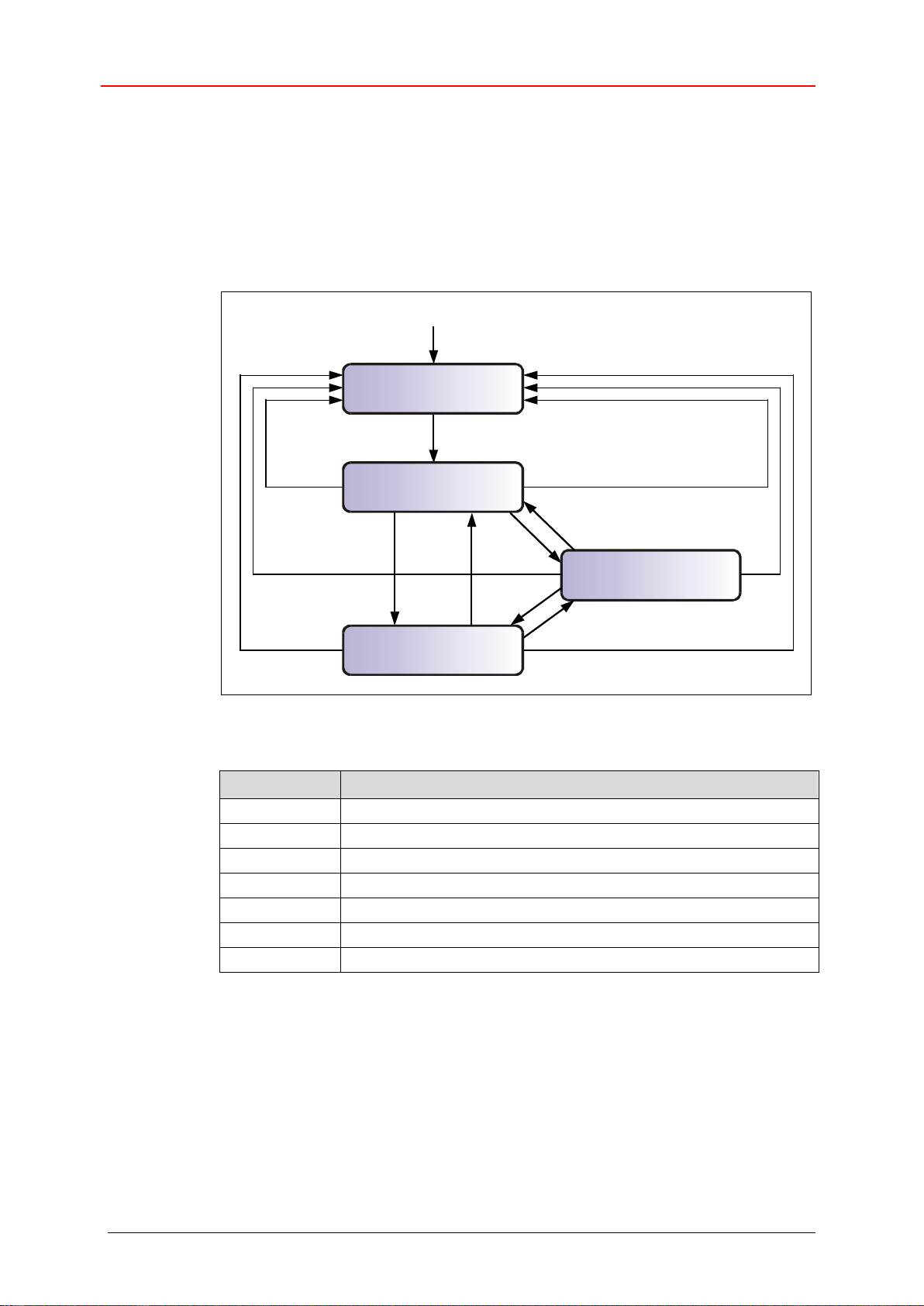
CANopen Informationen
Stop
(14)
(9)
(2)
(3)
(4)
(7)
(5)
(8)
(6)
Power ON oder Hardware-Reset
(13)
(12)
(10)
(11)
(1)
Initialisierung
Vor-Betriebszutand
Betriebszustand
Zustand
Beschreibung
(1)
Automatische Initialisierung nach dem Einschalten
(2)
Beendigung der Initialisierung --> Vor-Betriebszustand
(3),(6)
Start_Remote_Node --> Betriebszustand
(4),(7)
Enter_PRE-OPERATIONAL_State --> Vor-Betriebszustand
(5),(8)
Stop_Remote_Node --> Stop
(9),(10),(11)
Reset_Node --> Reset Knoten
(12),(13),(14)
Reset_Communication --> Reset Kommunikation
3.6 Netzwerkmanagement, NMT
Das Netzwerkmanagement unterstützt einen vereinfachten Hochlauf (Boot-Up) des
Netzes. Mit einem einzigen Telegramm lassen sich z.B. alle Geräte in den
Betriebszustand (Operational) versetzen.
Das Mess-System befindet sich nach dem Einschalten zunächst im "VorBetriebszustand", (2).
Abbildung 5: Boot-Up-Mechanismus des Netzwerkmanagements
TR-Electronic GmbH 2016, All Rights Reserved Printed in the Federal Republic of Germany
Page 20 of 127 TR - ECE - BA - DGB - 0128 - 01 11/20/2018

CCD
Node ID
Byte 0
Byte 1
CCD
Bedeutung
Zustand
-
Automatische Initialisierung nach dem Einschalten
(1)
-
Beendigung der Initialisierung --> PRE-OPERATIONAL
(2)
0x01
Start Remote Node
Teilnehmer soll in den Zustand OPERATIONAL wechseln und
damit den normalen Netzbetrieb starten
(3),(6)
0x02
Stop Remote Node
Teilnehmer soll in den Zustand STOPPED übergehen und damit
seine Kommunikation stoppen. Eine aktive
Verbindungsüberwachung bleibt aktiv.
(5),(8)
0x80
Enter PRE-OPERATIONAL
Teilnehmer soll in den Zustand PRE-OPERATIONAL gehen.
Alle Nachrichten außer PDOs können verwendet werden.
(4),(7)
0x81
Reset Node
Werte der Profilparameter des Objekts auf Default-Werte
setzen. Danach Übergang in den Zustand RESET
COMMUNICATION.
(9),(10),
(11)
0x82
Reset Communication
Teilnehmer soll in den Zustand RESET COMMUNICATION
gehen. Danach Übergang in den Zustand INITIALIZATION,
erster Zustand nach dem Einschalten.
(12),(13),
(14)
3.6.1 Netzwerkmanagement-Dienste
Das Network Management (NMT) hat die Aufgabe, Teilnehmer eines CANopenNetzwerks zu initialisieren, die Teilnehmer in das Netz aufzunehmen, zu stoppen und
zu überwachen.
NMT-Dienste werden von einem NMT-Master initiiert, der einzelne Teilnehmer (NMT-
Slave) über deren Node ID anspricht. Eine NMT-Nachricht mit der Node ID 0 richtet
sich an alle NMT-Slaves.
Das Mess-System entspricht einem NMT-Slave.
3.6.1.1 NMT-Dienste zur Gerätekontrolle
Die NMT-Dienste zur Gerätekontrolle verwenden die COB-ID 0 und erhalten so die
höchste Priorität.
Vom Datenfeld der CAN-Nachricht werden nur die ersten beiden Byte verwendet:
Folgende Kommandos sind definiert:
Tabelle 4: NMT-Dienste zur Gerätekontrolle
Printed in the Federal Republic of Germany TR-Electronic GmbH 2016, All Rights Reserved
11/20/2018 TR - ECE - BA - DGB - 0128 - 01 Page 21 of 127

CANopen Informationen
Index
Beschreibung
0x100C
Guard Time [ms]
Spätestens nach Ablauf des Zeitintervalls
Life Time = Guard Time x Life Time Factor [ms]
erwartet der NMT-Slave eine Zustandsabfrage durch
den Master.
Ist die Guard Time = 0, wird der entsprechende NMTSlave nicht vom Master überwacht.
Ist die Life Time = 0, ist das Life Guarding
abgeschaltet.
0x100D
Life Time Factor
3.6.1.2 NMT-Dienste zur Verbindungsüberwachung
Mit der Verbindungsüberwachung kann ein NMT-Master den Ausfall eines NMT-Slave
und/oder ein NMT-Slave den Ausfall des NMT-Master erkennen:
Node Guarding und Life Guarding:
Mit diesen Diensten überwacht ein NMT-Master einen NMT-Slave
Das Node Guarding wird dadurch realisiert, dass der NMT-Master in regelmäßigen
Abständen den Zustand eines NMT-Slave anfordert. Das Toggle-Bit 27 im „Node
Guarding Protocol“ toggelt nach jeder Abfrage:
Beispiel:
0x85, 0x05, 0x85 … --> kein Fehler
0x85, 0x05, 0x05 … --> Fehler
Ist zusätzlich das Life Guarding aktiv, erwartet der NMT-Slave innerhalb eines
bestimmten Zeitintervalls eine derartige Zustandsabfrage durch den NMT-Master. Ist
dies nicht der Fall, wechselt der Slave in den PRE-OPERATIONAL Zustand.
Die NMT-Dienste zur Verbindungsüberwachung verwenden den Funktionscode
1110 bin, also die COB-ID 0x700+Node ID.
Tabelle 5: Parameter für NMT-Dienste
TR-Electronic GmbH 2016, All Rights Reserved Printed in the Federal Republic of Germany
Page 22 of 127 TR - ECE - BA - DGB - 0128 - 01 11/20/2018

3.7 Layer setting services (LSS) und Protokolle
Die LSS-Dienste und Protokolle, dokumentiert in CiA DS-305 V3.0, unterstützen das
Abfragen und Konfigurieren verschiedener Parameter des Data Link Layers und des
Application Layers eines LSS-Slaves durch ein LSS-Master über das CAN Netzwerk.
Unterstützt werden folgende Parameter:
- Node-ID
- Baudrate
- LSS-Adresse, gemäß dem Identity Objekt 1018h
Der Zugriff auf den LSS-Slave erfolgt dabei über seine LSS-Adresse, bestehend aus:
- Vendor-ID
- Produkt-Code
- Revisions-Nummer und
- Serien-Nummer
Das Mess-System unterstützt folgende Dienste:
Switch state services
● Switch state selective
einen bestimmten LSS-Slave ansprechen
● Switch state global
alle LSS-Slaves ansprechen
Configuration services
● Configure Node-ID
Node-ID konfigurieren
● Configure bit timing parameters
Baudrate konfigurieren
● Activate bit timing parameters
Baudrate aktivieren
● Store configured parameters
konfigurierte Parameter speichern
Inquiry services
● Inquire LSS address
LSS-Adresse anfragen
● Inquire Node-ID
Node-ID anfragen
Identification services
● LSS identify remote slave
Identifizierung von LSS-Slaves innerhalb eines bestimmten Bereichs
● LSS identify slave
Rückmeldung der LSS-Slaves auf das vorherige Kommando
● LSS identify non-configured remote slave
Identifizierung von nicht-konfigurierten LSS-Slaves, Node-ID = FFh
● LSS identify non-configured slave
Rückmeldung der LSS-Slaves auf das vorherige Kommando
Printed in the Federal Republic of Germany TR-Electronic GmbH 2016, All Rights Reserved
11/20/2018 TR - ECE - BA - DGB - 0128 - 01 Page 23 of 127
CANopen Informationen
Dienste
LSS Waiting
LSS Configuration
Switch state global
Ja
Ja
Switch state selective
Ja
Nein
Activate bit timing parameters
Nein
Ja
Configure bit timing parameters
Nein
Ja
Configure Node-ID
Nein
Ja
Store configured parameters
Nein
Ja
Inquire LSS address
Nein
Ja
Inquire Node-ID
Nein
Ja
LSS identify remote slave
Ja
Ja
LSS identify slave
Ja
Ja
LSS identify non-configured remote slave
Ja
Ja
LSS identify non-configured slave
Ja
Ja
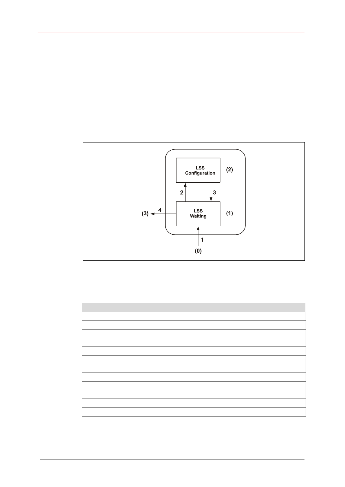
3.7.1 Finite state automaton, FSA
Der FSA entspricht einer Zustandsmaschine und definiert das Verhalten eines LSSSlaves. Gesteuert wird die Zustandsmaschine durch LSS COBs erzeugt durch einen
LSS-Master, oder NMT COBs erzeugt durch einen NMT-Master, oder lokale NMTZustandsübergänge.
Der LSS FSA unterstützt folgende Zustände:
(0) Initial: Pseudo-Zustand, zeigt die Aktivierung des FSAs an
(1) LSS waiting: Unterstützung aller Dienste wie unten angegeben
(2) LSS configuration: Unterstützung aller Dienste wie unten angegeben
(3) Final: Pseudo-Zustand, zeigt die Deaktivierung des FSAs an
Abbildung 6: LSS FSA Zustandsmaschine
Zustandsverhalten der unterstützten Dienste
TR-Electronic GmbH 2016, All Rights Reserved Printed in the Federal Republic of Germany
Page 24 of 127 TR - ECE - BA - DGB - 0128 - 01 11/20/2018

Übergang
Ereignisse
Aktionen
1
Automatischer Übergang nach der Initialisierung beim
Eintritt entweder in den NMT PRE OPERATIONAL
Zustand oder NMT STOPPED Zustand, oder NMT
RESET COMMUNICATION Zustand mit Node-ID = FFh.
keine
2
LSS 'switch state global' Kommando mit Parameter
'configuration_switch' oder 'switch state selective'
Kommando
keine
3
LSS 'switch state global' Kommando mit Parameter
'waiting_switch'
keine
4
Automatischer Übergang, wenn eine ungültige Node-ID
geändert wurde und die neue Node-ID erfolgreich im
nichtflüchtigen Speicher abgelegt werden konnte UND der
Zustand LSS waiting angefordert wurde.
keine
COB-ID
Bedeutung
0x7E4
LSS-Slave LSS-Master
0x7E5
LSS-Master LSS-Slave
CS
Daten
Byte 0
Byte 1
Byte 2
Byte 3
Byte 4
Byte 5
Byte 6
Byte 7
LSS FSA Zustandsübergänge
Sobald das LSS FSA weitere Zustandsübergänge im NMT FSA von NMT PRE
OPERATIONAL auf NMT STOPPED und umgekehrt erfährt, führt dies nicht zum
Wiedereintritt in den LSS FSA.
3.7.2 Übertragung von LSS-Diensten
Über die LSS-Dienste fordert der LSS-Master die einzelnen Dienste an, welche dann
durch den LSS-Slave ausgeführt werden. Die Kommunikation zwischen LSS-Master
und LSS-Slave wird über die implementierten LSS-Protokolle vorgenommen.
Ähnlich wie bei der SDO-Übertragung, werden auch hier zwei COB-IDs für das
Senden und Empfangen benutzt:
Tabelle 6: COB-IDs für Layer Setting Services (LSS)
3.7.2.1 LSS-Nachrichtenformat
Der maximal 8 Byte lange Datenbereich einer CAN-Nachricht wird von einem LSSDienst wie folgt belegt:
Tabelle 7: LSS-Nachricht
Byte 0 enthält die Command-Specifier (CS), danach folgen 7 Byte für die Daten.
Printed in the Federal Republic of Germany TR-Electronic GmbH 2016, All Rights Reserved
11/20/2018 TR - ECE - BA - DGB - 0128 - 01 Page 25 of 127

CANopen Informationen
0 1 2 3 4 5 6
7
COB-ID
CS
Mode
Reserved by CiA
0x7E5
0x04
0 = Waiting Mode
1 = Configuration Mode
0 1 2 3 4 5 6
7
COB-ID
CS
Vendor-ID (≙Index 1018h:01)
Reserved by CiA
0x7E5
0x40
LSB
MSB
0 1 2 3 4 5 6
7
COB-ID
CS
Product-Code (≙Index 1018h:02)
Reserved by CiA
0x7E5
0x41
LSB
MSB
0 1 2 3 4 5 6
7
COB-ID
CS
Revision-No. (≙Index 1018h:03)
Reserved by CiA
0x7E5
0x42
LSB
MSB
0 1 2 3 4 5 6
7
COB-ID
CS
Serial-No. (≙Index 1018h:04)
Reserved by CiA
0x7E5
0x43
LSB
MSB
0 1 2 3 4 5 6
7
COB-ID
CS
Reserved by CiA
0x7E4
0x44
3.7.3 Switch mode Protokolle
3.7.3.1 Switch state global Protokoll
Das angegebene Protokoll hat den Switch state global service implementiert
und steuert die LSS-Zustandsmaschine des LSS-Slaves. Über den LSS-Master können
alle LSS-Slaves im Netzwerk in den LSS waiting oder LSS configuration
Zustand versetzt werden.
LSS-Master --> LSS-Slave
3.7.3.2 Switch state selective Protokoll
Das angegebene Protokoll hat den Switch state selective service
implementiert und steuert die LSS-Zustandsmaschine des LSS-Slaves. Über den LSSMaster kann nur der LSS-Slave im Netzwerk in den LSS configuration Zustand
versetzt werden, dessen LSS- Adressattribute der LSS-Adresse entsprechen.
LSS-Master --> LSS-Slave
LSS-Slave --> LSS-Master
TR-Electronic GmbH 2016, All Rights Reserved Printed in the Federal Republic of Germany
Page 26 of 127 TR - ECE - BA - DGB - 0128 - 01 11/20/2018

0 1 2 3 4 5 6
7
COB-ID
CS
Node-ID
Reserved by CiA
0x7E5
0x11
0x01…0x7F
0 1 2 3 4 5 6
7
COB-ID
CS
Error Code
Spec. Error
Reserved by CiA
0x7E4
0x11
3.7.4 Configuration Protokolle
3.7.4.1 Configure Node-ID Protokoll
Das angegebene Protokoll hat den Configure Node-ID service implementiert.
Über den LSS-Master kann die Node-ID eines einzelnen LSS-Slaves im Netzwerk
konfiguriert werden. Hierbei darf sich nur ein LSS-Slave im Zustand
LSS configuration befinden. Zur Speicherung der neuen Node-ID muss das
Store configuration protocol an den LSS-Slave übertragen werden. Um die
neue Node-ID zu aktivieren, muss der NMT-Dienst Reset Communication (0x82)
aufgerufen werden.
LSS-Master --> LSS-Slave
LSS-Slave --> LSS-Master
Node-ID
1…127: gültige Adressen
Error Code
0: Ausführung erfolgreich
1: Node-ID außerhalb Bereich, 1…127
2…254: Reserved
255: applikationsspezifischer Fehler aufgetreten
Specific Error
Wenn Error Code = 255 --> applikationsspezifischer Fehler aufgetreten,
sonst reserviert durch die CiA
Printed in the Federal Republic of Germany TR-Electronic GmbH 2016, All Rights Reserved
11/20/2018 TR - ECE - BA - DGB - 0128 - 01 Page 27 of 127

CANopen Informationen
0 1 2 3 4 5 6
7
COB-ID
CS
Table Selector
Table Index
Reserved by CiA
0x7E5
0x13
0
0x00…0x07
0 1 2 3 4 5 6
7
COB-ID
CS
Error Code
Spec. Error
Reserved by CiA
0x7E4
0x13
3.7.4.2 Configure bit timing parameters Protokoll
Das angegebene Protokoll hat den Configure bit timing parameters
service implementiert. Über den LSS-Master kann die Baudrate eines einzelnen LSS-
Slaves im Netzwerk konfiguriert werden. Hierbei darf sich nur ein LSS-Slave im Zustand
LSS configuration befinden. Zur Speicherung der neuen Baudrate muss das
Store configuration protocol an den LSS-Slave übertragen werden.
LSS-Master --> LSS-Slave
LSS-Slave --> LSS-Master
Table Selector
0: Standard CiA Baudraten-Tabelle
Table Index
0: 1 Mbit/s
1: 800 kbit/s
2: 500 kbit/s
3: 250 kbit/s
4: 125 kbit/s
6: 50 kbit/s
7: 20 kbit/s
8: 10 kbit/s
Error Code
0: Ausführung erfolgreich
1: selektierte Baudrate nicht unterstützt
2…254: Reserved
255: applikationsspezifischer Fehler aufgetreten
Specific Error
Wenn Error Code = 255 --> applikationsspezifischer Fehler aufgetreten,
sonst reserviert durch die CiA
TR-Electronic GmbH 2016, All Rights Reserved Printed in the Federal Republic of Germany
Page 28 of 127 TR - ECE - BA - DGB - 0128 - 01 11/20/2018

0 1 2 3 4 5 6
7
COB-ID
CS
Switch Delay [ms]
Reserved by CiA
0x7E5
0x15
LSB
MSB
0 1 2 3 4 5 6
7
COB-ID
CS
Reserved by CiA
0x7E5
0x17
0 1 2 3 4 5 6
7
COB-ID
CS
Error Code
Spec. Error
Reserved by CiA
0x7E4
0x17
3.7.4.3 Activate bit timing parameters Protokoll
Das angegebene Protokoll hat den Activate bit timing parameters service
implementiert und aktiviert die über Configure bit timing parameters protocol
festgelegte Baudrate bei allen LSS-Slaves im Netzwerk, die sich im Zustand
LSS configuration befinden.
LSS-Master --> LSS-Slave
Switch Delay
Der Parameter Switch Delay definiert die Länge zweier Verzögerungsperioden
(D1, D2) mit gleicher Länge. Damit wird das Betreiben des Busses mit
unterschiedlichen Baudratenparametern verhindert.
Nach Ablauf der Zeit D1 und einer individuellen Verarbeitungsdauer wird die
Umschaltung intern im LSS-Slave vorgenommen. Nach Ablauf der Zeit D2 meldet
sich der LSS-Slave wieder mit CAN-Nachrichten und der neu eingestellten
Baudrate.
Es gilt:
Switch Delay > längste vorkommende Verarbeitungsdauer eines LSS-Slaves
3.7.4.4 Store configuration Protokoll
Das angegebene Protokoll hat den Store configuration service implementiert.
Über den LSS-Master können die konfigurierten Parameter eines einzelnen LSS-Slaves
im Netzwerk in den nichtflüchtigen Speicher abgelegt werden. Hierbei darf sich nur ein
LSS-Slave im Zustand LSS configuration befinden.
LSS-Master --> LSS-Slave
LSS-Slave --> LSS-Master
Error Code
0: Ausführung erfolgreich
1: Store configuration nicht unterstützt
2: Zugriff auf Speichermedium fehlerhaft
3…254: Reserved
255: applikationsspezifischer Fehler aufgetreten
Specific Error
Wenn Error Code = 255 --> applikationsspezifischer Fehler aufgetreten,
sonst reserviert durch die CiA
Printed in the Federal Republic of Germany TR-Electronic GmbH 2016, All Rights Reserved
11/20/2018 TR - ECE - BA - DGB - 0128 - 01 Page 29 of 127

CANopen Informationen
0 1 2 3 4 5 6
7
COB-ID
CS
Reserved by CiA
0x7E5
0x5A
0 1 2 3 4 5 6
7
COB-ID
CS
Vendor-ID (≙Index 1018h:01)
Reserved by CiA
0x7E4
0x5A
LSB
MSB
0 1 2 3 4 5 6
7
COB-ID
CS
Reserved by CiA
0x7E5
0x5B
0 1 2 3 4 5 6
7
COB-ID
CS
Product-Code (≙Index 1018h:02)
Reserved by CiA
0x7E4
0x5B
LSB
MSB
3.7.5 Inquire LSS-Address Protokolle
3.7.5.1 Inquire identity Vendor-ID Protokoll
Das angegebene Protokoll hat den Inquire LSS address service implementiert.
Über den LSS-Master kann die Vendor-ID eines einzelnen LSS-Slaves im Netzwerk
ausgelesen werden. Hierbei darf sich nur ein LSS-Slave im Zustand
LSS configuration befinden.
LSS-Master --> LSS-Slave
LSS-Slave --> LSS-Master
3.7.5.2 Inquire identity Product-Code Protokoll
Das angegebene Protokoll hat den Inquire LSS address service implementiert.
Über den LSS-Master kann der Produkt-Code eines einzelnen LSS-Slaves im Netzwerk
ausgelesen werden. Hierbei darf sich nur ein LSS-Slave im Zustand
LSS configuration befinden.
LSS-Master --> LSS-Slave
LSS-Slave --> LSS-Master
TR-Electronic GmbH 2016, All Rights Reserved Printed in the Federal Republic of Germany
Page 30 of 127 TR - ECE - BA - DGB - 0128 - 01 11/20/2018

0 1 2 3 4 5 6
7
COB-ID
CS
Reserved by CiA
0x7E5
0x5C
0 1 2 3 4 5 6
7
COB-ID
CS
Revision-No. (≙Index 1018h:03)
Reserved by CiA
0x7E4
0x5C
LSB
MSB
0 1 2 3 4 5 6
7
COB-ID
CS
Reserved by CiA
0x7E5
0x5D
0 1 2 3 4 5 6
7
COB-ID
CS
Serial-No. (≙Index 1018h:04)
Reserved by CiA
0x7E5
0x5D
LSB
MSB
3.7.5.3 Inquire identity Revision-Number Protokoll
Das angegebene Protokoll hat den Inquire LSS address service implementiert.
Über den LSS-Master kann die Revisionsnummer eines einzelnen LSS-Slaves im
Netzwerk ausgelesen werden. Hierbei darf sich nur ein LSS-Slave im Zustand
LSS configuration befinden.
LSS-Master --> LSS-Slave
LSS-Slave --> LSS-Master
3.7.5.4 Inquire identity Serial-Number Protokoll
Das angegebene Protokoll hat den Inquire LSS address service implementiert.
Über den LSS-Master kann die Seriennummer eines einzelnen LSS-Slaves im
Netzwerk ausgelesen werden. Hierbei darf sich nur ein LSS-Slave im Zustand
LSS configuration befinden.
LSS-Master --> LSS-Slave
LSS-Slave --> LSS-Master
Printed in the Federal Republic of Germany TR-Electronic GmbH 2016, All Rights Reserved
11/20/2018 TR - ECE - BA - DGB - 0128 - 01 Page 31 of 127

CANopen Informationen
0 1 2 3 4 5 6
7
COB-ID
CS
Reserved by CiA
0x7E5
0x5E
0 1 2 3 4 5 6
7
COB-ID
CS
Node-ID
Reserved by CiA
0x7E4
0x5E
0x01…0x7F
3.7.6 Inquire Node-ID Protokoll
Das angegebene Protokoll hat den Inquire Node-ID service implementiert. Über
den LSS-Master kann die Node-ID eines einzelnen LSS-Slaves im Netzwerk
ausgelesen werden. Hierbei darf sich nur ein LSS-Slave im Zustand
LSS configuration befinden.
LSS-Master --> LSS-Slave
LSS-Slave --> LSS-Master
Node-ID
Entspricht der Node-ID des selektierten Gerätes. Wenn die Node-ID eben gerade
erst über den Configure Node-ID service geändert wurde, wird die
ursprüngliche Node-ID zurückgemeldet. Erst nach Ausführung des NMT-Dienstes
Reset Communication (0x82) wird die aktuelle Node-ID zurückgemeldet.
TR-Electronic GmbH 2016, All Rights Reserved Printed in the Federal Republic of Germany
Page 32 of 127 TR - ECE - BA - DGB - 0128 - 01 11/20/2018

0 1 2 3 4 5 6
7
COB-ID
CS
Vendor-ID (≙Index 1018h:01)
Reserved by CiA
0x7E5
0x46
LSB
MSB
0 1 2 3 4 5 6
7
COB-ID
CS
Product-Code (≙Index 1018h:02)
Reserved by CiA
0x7E5
0x47
LSB
MSB
0 1 2 3 4 5 6
7
COB-ID
CS
Revision-No. LOW
Reserved by CiA
0x7E5
0x48
LSB
MSB
0 1 2 3 4 5 6
7
COB-ID
CS
Revision-No. HIGH
Reserved by CiA
0x7E5
0x49
LSB
MSB
0 1 2 3 4 5 6
7
COB-ID
CS
Serial-No. LOW
Reserved by CiA
0x7E5
0x4A
LSB
MSB
0 1 2 3 4 5 6
7
COB-ID
CS
Serial-No. HIGH
Reserved by CiA
0x7E5
0x4B
LSB
MSB
0 1 2 3 4 5 6
7
COB-ID
CS
Reserved by CiA
0x7E4
0x4F
3.7.7 Identification Protokolle
3.7.7.1 LSS identify remote slave Protokoll
Das angegebene Protokoll hat den LSS identify remote slave service
implementiert. Über den LSS-Master können LSS-Slaves im Netzwerk in einem
bestimmten Bereich identifiziert werden. Alle LSS-Slaves, die der angegebenen VendorID, Product-Code, Revision-No. – Bereich und Serial-No. – Bereich entsprechen,
antworten mit dem LSS identify slave protocol.
LSS-Master --> LSS-Slave
3.7.7.2 LSS identify slave Protokoll
Das angegebene Protokoll hat den LSS identify slave service implementiert.
Alle LSS-Slaves, die den im LSS identify remote slave protocol
angegebenen LSS-Adress-Attributen entsprechen, antworten mit diesem Protokoll.
LSS-Slave --> LSS-Master
Printed in the Federal Republic of Germany TR-Electronic GmbH 2016, All Rights Reserved
11/20/2018 TR - ECE - BA - DGB - 0128 - 01 Page 33 of 127

CANopen Informationen
0 1 2 3 4 5 6
7
COB-ID
CS
Reserved by CiA
0x7E5
0x4C
0 1 2 3 4 5 6
7
COB-ID
CS
Reserved by CiA
0x7E4
0x50
3.7.7.3 LSS identify non-configured remote slave Protokoll
Das angegebene Protokoll hat den LSS identify non-configured remote
slave service implementiert. Über den LSS-Master werden alle nicht-
konfigurierten LSS-Slaves (Node-ID = FFh) im Netzwerk identifiziert. Die betreffenden
LSS-Slaves antworten mit dem LSS identify non-configured slave
protocol.
LSS-Master --> LSS-Slave
3.7.7.4 LSS identify non-configured slave Protokoll
Das angegebene Protokoll hat den LSS identify non-configured slave
service implementiert. Alle LSS-Slaves, die eine ungültige Node-ID (FFh) besitzen,
antworten nach Ausführung des LSS identify non-configured remote slave
protocol mit diesem Protokoll.
LSS-Slave --> LSS-Master
TR-Electronic GmbH 2016, All Rights Reserved Printed in the Federal Republic of Germany
Page 34 of 127 TR - ECE - BA - DGB - 0128 - 01 11/20/2018

3.8 Geräteprofil
Die CANopen Geräteprofile beschreiben das "was" der Kommunikation. In ihnen wird
die Bedeutung der übertragenen Daten eindeutig und hersteller-unabhängig
festgelegt. So lassen sich die Grundfunktionen einer jeden Geräteklasse
z.B. für Encoder: CiA DS-406
einheitlich ansprechen. Auf der Grundlage dieser standardisierten Profile kann auf
identische Art und Weise über den Bus auf CANopen Geräte zugegriffen werden.
Damit sind Geräte, die dem gleichen Geräteprofil folgen, weitgehend untereinander
austauschbar.
Weitere Informationen zum CANopen erhalten Sie auf Anfrage von der
CAN in Automation Nutzer- und Herstellervereinigung (CiA) unter nachstehender
Adresse:
CAN in Automation
Am Weichselgarten 26
DE-91058 Erlangen
Tel. +49-9131-69086-0
Fax +49-9131-69086-79
Website: www.can-cia.org
e-mail: headquarters@can-cia.org
Printed in the Federal Republic of Germany TR-Electronic GmbH 2016, All Rights Reserved
11/20/2018 TR - ECE - BA - DGB - 0128 - 01 Page 35 of 127

Installation / Inbetriebnahmevorbereitung
Kabelquerschnitt
10 kbit/s
20 kbit/s
50 kbit/s
125 kbit/s
250 kbit/s
500 kbit/s
800 kbit/s
1 Mbit/s
0.25 mm2 – 0.34 mm2
5000 m
2500 m
1000 m
500 m
250 m
100 m
50 m
25 m
Um einen sicheren und störungsfreien Betrieb zu gewährleisten, sind die
- ISO 11898,
- die Empfehlungen der CiA DR 303-1
(CANopen cabling and connector pin assignment)
- und sonstige einschlägige Normen und Richtlinien zu beachten!
Insbesondere sind die EMV-Richtlinie sowie die Schirmungs- und Erdungsrichtlinien
in den jeweils gültigen Fassungen zu beachten!
4 Installation / Inbetriebnahmevorbereitung
Das CANopen System wird in Bustopologie mit Abschlusswiderständen (120 Ohm)
am Anfang und am Ende verkabelt. Stichleitungen sollten möglichst vermieden
werden. Das Kabel ist als geschirmtes Twisted Pair Kabel auszuführen und sollte eine
Impedanz von 120 Ohm und einen Widerstand von 70 m/m haben. Die
Datenübertragung erfolgt über die Signale CAN_H und CAN_L mit einem
gemeinsamen GND als Datenbezugspotential. Optional kann auch eine 24 Volt
Versorgungsspannung mitgeführt werden.
In einem CANopen Netzwerk können maximal 127 Teilnehmer angeschlossen
werden. Das Mess-System unterstützt den Node-ID Bereich von 1–127 und die
Baudraten:
● 10 kbit/s
● 20 kbit/s
● 50 kbit/s
● 125 kbit/s
● 250 kbit/s
● 500 kbit/s
● 800 kbit/s
● 1 Mbit/s
Die Länge eines CANopen Netzwerkes ist abhängig von der Übertragungsgeschwindigkeit und ist
nachfolgend dargestellt:
TR-Electronic GmbH 2016, All Rights Reserved Printed in the Federal Republic of Germany
Page 36 of 127 TR - ECE - BA - DGB - 0128 - 01 11/20/2018

4.1 Anschluss
Die Steckerbelegung ist abhängig von der Geräteausführung und ist deshalb bei
jedem Mess-System auf dem Typenschild als Steckerbelegungsnummer vermerkt und
kann über den folgenden Link heruntergeladen werden:
www.tr-electronic.de/service/downloads/steckerbelegungen.html?L=0%27
Bei der Auslieferung des Mess-Systems wird jeweils eine gerätespezifische
Steckerbelegung in gedruckter Form beigelegt.
4.2 Bus-Terminierung
Für die Busterminierung muss ein 120 Ohm Wiederstand zwischen CAN_H und
CAN_L verwendet werden.
4.3 Einschalten der Versorgungsspannung
Nachdem der Anschluss vorgenommen worden ist, kann die Versorgungsspannung
eingeschaltet werden.
Nach dem Einschalten der Versorgungsspannung und Beendigung der Initialisierung
geht das Mess-System in den Vor-Betriebszustand (PRE-OPERATIONAL). Dieser
Zustand wird durch die Boot-Up-Meldung „COB-ID 0x700+Node ID“ bestätigt. Falls
das Mess-System einen internen Fehler erkennt, wird eine Emergency-Meldung mit
dem Fehlercode übertragen (siehe Kapitel „Emergency-Meldung“, Seite 59).
Im PRE-OPERATIONAL-Zustand ist zunächst nur eine Parametrierung über ServiceDaten-Objekte möglich. Es ist aber möglich, PDOs unter Nutzung von SDOs zu
konfigurieren. Ist das Mess-System in den Zustand OPERATIONAL überführt worden,
ist auch eine Übertragung von PDOs möglich.
4.4 Einstellen der Node-ID und Baudrate
Die Node-ID und Baudrate sind entweder kundenspezifisch ab Werk programmiert
und können zu Servicezwecken nur mittels der Programmiersoftware TRWinProg und
einem PC-Adapter geändert werden oder sie sind über LSS-Dienste vom Kunden
programmierbar. Dazu muss in der Programmiersoftware TRWinProg die Option „LSS
benutzen“ aktiviert sein.
Ist die Option „LSS benutzen“ aktiv, besitzt das Mess-System im
Auslieferungszustand die Node-ID 10 (0x0A) und eine Baudrate von 1 MBaud.
Printed in the Federal Republic of Germany TR-Electronic GmbH 2016, All Rights Reserved
11/20/2018 TR - ECE - BA - DGB - 0128 - 01 Page 37 of 127

Installation / Inbetriebnahmevorbereitung
4.4.1 Konfiguration der Node-ID, Ablauf
Annahme:
- LSS-Adresse unbekannt
- der LSS-Slave ist der einzige Teilnehmer in Netzwerk
- es soll die Node-ID 12 dez. eingestellt werden
Vorgehensweise:
LSS-Slave mit dem Dienst 04 Switch state global protocol,
Mode = 1 in den Zustand Configuration state bringen.
Dienst 17 Configure Node-ID protocol, Node-ID = 12 ausführen.
--> Rückmeldung abwarten und erfolgreiche Ausführung überprüfen,
--> Error Code = 0.
Dienst 23 Store configuration protocol ausführen.
--> Rückmeldung abwarten und erfolgreiche Ausführung überprüfen,
--> Error Code = 0.
LSS-Slave mit dem Dienst 04 Switch state global protocol,
Mode = 0 in den Zustand Waiting state bringen.
NMT-Dienst Reset Communication (0x82) aufrufen, damit die neue Node-ID
aktiv wird.
4.4.2 Konfiguration der Baudrate, Ablauf
Annahme:
- LSS-Adresse unbekannt
- der LSS-Slave ist der einzige Teilnehmer in Netzwerk
- es soll die Baudrate 125 kbit/s eingestellt werden
Vorgehensweise:
NMT-Dienst Stop Remote Node (0x02) aufrufen, um den LSS-Slave in den
Stopped state zu bringen. Der LSS-Slave sollte keine CAN-Nachrichten
mehr senden --> Heartbeat abgeschaltet.
LSS-Slave mit dem Dienst 04 Switch state global protocol,
Mode = 1 in den Zustand Configuration state bringen.
Dienst 19 Configure bit timing parameters protocol ausführen,
Table Selector = 0, Table Index = 4
--> Rückmeldung abwarten und erfolgreiche Ausführung überprüfen,
--> Error Code = 0.
Dienst 21 Activate bit timing parameters protocol aufrufen, damit
die neue Baudrate aktiv wird.
Dienst 23 Store configuration protocol ausführen.
--> Rückmeldung abwarten und erfolgreiche Ausführung überprüfen,
--> Error Code = 0.
LSS-Slave mit dem Dienst 04 Switch state global protocol,
Mode = 0 in den Zustand Waiting state bringen.
TR-Electronic GmbH 2016, All Rights Reserved Printed in the Federal Republic of Germany
Page 38 of 127 TR - ECE - BA - DGB - 0128 - 01 11/20/2018

5 Inbetriebnahme
5.1 CAN – Schnittstelle
Die CAN-Bus-Schnittstelle ist durch die internationale Norm ISO/DIS 11898 definiert
und spezifiziert die zwei untersten Schichten des CAN Referenz-Models.
Die CAN-Bus-Schnittstelle mit dem Bustreiber PCA82C251 ist galvanisch von der
Mess-System-Elektronik getrennt und wird über einen internen DC/DC-Konverter
gespeist. Eine externe Spannungsversorgung für den Bustreiber ist nicht notwendig.
Die Konvertierung der Mess-System-Information in das CAN-Protokoll (CAN 2.0A)
geschieht über den CAN-Kontroller SJA1000. Die Funktion des CAN-Kontrollers wird
durch einen Watchdog überwacht.
Das CANopen Kommunikationsprofil (CiA Standard DS 301) basiert auf dem CAN
Application Layer (CAL) und beschreibt, wie die Dienste von Geräten benutzt werden.
Das CANopen Profil erlaubt die Definition von Geräteprofilen für eine dezentralisierte
E/A.
Das Mess-System mit CANopen Protokoll unterstützt das Geräteprofil für Encoder
(CiA Draft Standard 406, Version 3.2). Die Mess-Systeme unterstützen auch den
erweiterten Funktionsumfang in Klasse C2.
Die Kommunikations-Funktionalität und Objekte, welche im Encoderprofil benutzt
werden, werden in einer EDS-Datei (Electronic Data Sheet) beschrieben. Wird ein
CANopen Konfigurations-Hilfsprogramm benutzt (z.B. CANSETTER), kann der
Benutzer die Objekte (SDO´s) des Mess-Systems auslesen und die Funktionalität
programmieren.
Die Auswahl der Übertragungsrate und Node-ID (Geräteadresse) erfolgt über LSS.
5.1.1 EDS-Datei
Die EDS-Datei (elektronisches Datenblatt) enthält alle Informationen über die MessSystem-spezifischen Parameter sowie Betriebsarten des Mess-Systems. Die EDSDatei wird durch das CANopen-Netzwerkkonfigurationswerkzeug eingebunden, um
das Mess-System ordnungsgemäß konfigurieren bzw. in Betrieb nehmen zu können.
Download:
Die EDS-Datei hat den Dateinamen "CMV36M_CANopen.eds".
www.tr-electronic.de/f/TR-ECE-ID-MUL-0054
Printed in the Federal Republic of Germany TR-Electronic GmbH 2016, All Rights Reserved
11/20/2018 TR - ECE - BA - DGB - 0128 - 01 Page 39 of 127

Kommunikations-Profil
31
30
29
28
11
10
0
Valid
RTR
Frame
0 0000h
11-Bit CAN-ID
Bit(s)
Beschreibung
Valid
0: PDO existiert / ist gültig
1: PDO existiert nicht / ist nicht gültig
RTR
0: Remote Frame erlaubt für dieses PDO
1: kein Remote Frame erlaubt für dieses PDO
Frame
0: 11-Bit CAN-ID gültig, normaler CAN Frame
1: 29-Bit CAN-ID gültig, erweiterter CAN Frame (nicht unterstützt)
11-Bit CAN-ID
11-Bit CAN-ID des normalen CAN Frames
Wert
Beschreibung
01h
Istwert wird synchron über einen Remote-Frame oder SYNCTelegramm übertragen
02h
Istwert wird synchron über einen Remote-Frame oder zyklisch nach
jedem 2. SYNC-Telegramm übertragen
03h
Istwert wird synchron über einen Remote-Frame oder zyklisch nach
jedem 3. SYNC-Telegramm übertragen
…
…
F0h
Istwert wird synchron über einen Remote-Frame oder zyklisch nach
jedem 240. SYNC-Telegramm übertragen
FDh
Istwert kann nur über einen Remote-Frame übertragen werden
FEh
Istwert wird asynchron mit dem Timerwert aus den Objekten 1800h und
1801h übertragen (Subindex 5)
6 Kommunikations-Profil
Generell existieren zwei Arten von Prozessdaten-Objekten (PDO):
1. Sende-PDOs (TPDO), um Daten zu übertragen
2. Empfangs-PDOs (RPDO), um Daten zu empfangen
Vom Mess-System werden nur Sende-PDOs unterstützt, um den Positionswert zu
übertragen.
Die TPDOs werden festgelegt durch die TPDO Kommunikationsparameter 1800h1801h und die TPDO Parameter 1A00h-1A01h. Während die TPDO
Kommunikationsparameter die Kommunikationsmöglichkeiten beschreiben, beinhalten
die TPDO Parameter 1A00h-1A01h Informationen über den Inhalt des TPDOs.
6.1 Aufbau der Kommunikationsparameter, 1800h-1801h
Subindex 0 beinhaltet die Anzahl der gültigen Objekteinträge.
Subindex 1 beinhaltet die COB-ID für das TPDO:
MSB LSB
Subindex 2 definiert die Übertragungsart für das TPDO:
TR-Electronic GmbH 2016, All Rights Reserved Printed in the Federal Republic of Germany
Page 40 of 127 TR - ECE - BA - DGB - 0128 - 01 11/20/2018

31
16
15 8 7
0
Index
Subindex
Länge in Bit
Subindex 3 beinhaltet die Sperrzeit für das TPDO. Die Zeit definiert die Mindestzeit
zwischen zwei hintereinander folgenden PDO Übertragungen, wenn die
Übertragungsart FEh eingestellt wurde. Der Wert wird definiert als Vielfaches von
100 µs. Der Wert 0 deaktiviert die Sperrzeit.
Der Wert darf nicht geändert werden während das PDO existiert
(Bit 31 von Subindex 1 = 0).
Subindex 4 wird nicht unterstützt.
Subindex 5 beinhaltet den Event-Timer. Die Zeit definiert die Maximalzeit zwischen
zwei hintereinander folgenden PDO Übertragungen, wenn die Übertragungsart FEh
eingestellt wurde. Der Wert wird definiert als Vielfaches von 1 ms. Der Wert 0
deaktiviert den Event-Timer.
Der Event-Timer, Subindex 5 des Kommunikationsparameters 1800h, ist fest
verknüpft mit dem Object 6200h: Cyclic timer. Dies bedeutet, dass eine Änderung des
Event-Timers sich auch im Cyclic Timer auswirkt und umgekehrt.
Der Kommunikationsparameter 1801h benutzt ausschließlich seinen eigenen Timer,
Zugriff über Subindex 5.
6.2 Aufbau der Parameter, 1A00h-1A01h
Subindex 0 beinhaltet die Anzahl der gültigen Objekteinträge. Der Wert 0 deaktiviert
das jeweilige Objekt.
Subindex 1 beinhaltet den Mess-System-Positionswert. Das Objekt beschreibt den
Inhalt des PDOS durch dessen Index, Subindex und der Länge in Bit:
MSB LSB
Printed in the Federal Republic of Germany TR-Electronic GmbH 2016, All Rights Reserved
11/20/2018 TR - ECE - BA - DGB - 0128 - 01 Page 41 of 127
Kommunikations-Profil
COB-ID
Positionsausgabewert
11 Bit
Byte 0
Byte 1
Byte 2
Byte 3
27 bis 20
215 bis 28
223 bis 216
231 bis 224
Index
Subindex
Kommentar
Standardwert
Attr.
1800h
0
größter unterstützter Subindex
5
ro
1
COB-ID benützt durch TPDO 1
180h + Node-ID
rw
2
Übertragungsart
254
rw
3
Sperrzeit
0
rw
4
-
- - 5
Event Timer
0
rw
1A00h
0
größter unterstützter Subindex
1, max 8
rw
1
Positionswert
6004 0020h
rw
Index
Subindex
Kommentar
Standardwert
Attr.
1801h
0
größter unterstützter Subindex
5
ro
1
COB-ID benützt durch TPDO 2
280h + Node-ID
rw
2
Übertragungsart
1
rw
3
Sperrzeit
0
rw
4
-
- - 5
Event Timer
0
rw
1A01h
0
größter unterstützter Subindex
1, max 8
rw
1
Positionswert
6004 0020h
rw
6.3 Übertragungsarten
Im Mess-System sind zwei Prozessdaten-Objekte (PDO) implementiert. Eines wird für
die Asynchron-Übertragung und das Andere für die Synchron-Übertragungsfunktionen
benötigt.
Der Istwert wird im Binärcode übertragen:
Weitere Informationen zur Übertragung des Mess-System-Positionswertes, siehe Kap.
10 „Übertragung des Mess-System-Positionswertes“ auf Seite 60.
6.3.1 Erstes Sende-Prozessdaten-Objekt (asynchron)
Dieses TPDO überträgt in der Standardeinstellung den Mess-System-Istwert
asynchron. Der Timerwert ist im Subindex 5 bzw. Index 6200h gespeichert. Die
Standardeinstellung des Timers ist 0, d.h. der Timer ist abgeschaltet.
6.3.2 Zweites Sende-Prozessdaten-Objekt (synchron)
Dieses TPDO überträgt in der Standardeinstellung den Mess-System-Istwert synchron
(einmalig auf Anforderung). Anforderung über Remote-Frame (Standard COB-ID:
280h+Node-ID) oder SYNC-Telegramm (Standard COB-ID: 080h).
TR-Electronic GmbH 2016, All Rights Reserved Printed in the Federal Republic of Germany
Page 42 of 127 TR - ECE - BA - DGB - 0128 - 01 11/20/2018

Index (h)
Objekt
Name
Typ
Attr.
M/O
Seite
1000
VAR
Gerätetyp
Unsigned32
ro M 44
1001
VAR
Fehlerregister
Unsigned8
ro M 44
1002
VAR
Hersteller-Status-Register
Unsigned32
ro O 44
1003
ARRAY
Vordefiniertes Fehlerfeld
Unsigned32
rw O 45
1005
VAR
COB-ID SYNC-Nachricht
Unsigned32
rw O 45
1008 1)
VAR
Hersteller Gerätenamen
Vis-String
const O 46
1009 1)
VAR
Hardwareversion
Vis-String
const O 46
100A 1)
VAR
Softwareversion
Vis-String
const O 46
100C
VAR
Guard-Time (Überwachungszeit)
Unsigned16
rw O 46
100D
VAR
Life-Time-Faktor (Zeitdauer-Faktor)
Unsigned8
rw O 46
1010
ARRAY
Parameter abspeichern
Unsigned32
rw O 47
1014
VAR
COB-ID EMCY
Unsigned32
rw O 48
1016
ARRAY
Consumer Heartbeat Time
Unsigned32
rw O 48
1017
VAR
Producer Heartbeat Time
Unsigned16
rw O 49
1018
RECORD
Identity Objekt
Identity (23h)
ro M 49
1021 1)
VAR
EDS abspeichern
Domain
ro O 50
1022
VAR
EDS Speicherformat
Unsigned8
ro M 50
1029
ARRAY
Verhalten im Fehlerfall
Unsigned8
rw O 50
1F50 1)
ARRAY
Programmdaten
Domain
rw O 50
1F51
ARRAY
Programmsteuerung
Unsigned8
rw M 51
1F56
ARRAY
Programm Software Identifikation
Unsigned32
ro M 51
1F57
ARRAY
Programmstatus
Unsigned32
ro M 52
1F80
VAR
NMT Autostart
Unsigned32
rw O 52
7 Kommunikationsspezifische Standard-Objekte (CiA DS-301)
Folgende Tabelle zeigt eine Übersicht der unterstützten Indexe im
Kommunikationsprofilbereich:
M = Mandatory (zwingend)
O = Optional
Tabelle 8: Kommunikationsspezifische Standard-Objekte
1)
segmentiertes Lesen
Printed in the Federal Republic of Germany TR-Electronic GmbH 2016, All Rights Reserved
11/20/2018 TR - ECE - BA - DGB - 0128 - 01 Page 43 of 127

Kommunikationsspezifische Standard-Objekte (CiA DS-301)
Gerätetyp
Geräte-Profil-Nummer
Encoder-Typ
Byte 0
Byte 1
Byte 2
Byte 3
196h
27 bis 20
215 bis 28
Code
Definition
Default
01
Absoluter Single-Turn Encoder
02
Absoluter Multi-Turn Encoder
X
Bit
Bedeutung
0
generischer Fehler
1
0 2 0
3
0 4 Kommunikationsfehler (Überlauf, Fehlerstatus)
5
0 6 0 7 0
7.1 Objekt 1000h: Gerätetyp
Beinhaltet Information über den Gerätetyp. Das Objekt mit Index 1000h beschreibt
den Gerätetyp und seine Funktionalität. Es besteht aus einem 16 Bit Feld, welches
das benutzte Geräteprofil beschreibt (Geräteprofil-Nr. 406 = 196h) und ein zweites 16
Bit Feld, welches Informationen über den Gerätetyp liefert.
Unsigned32
Encoder-Typ
7.2 Objekt 1001h: Fehlerregister
Das Fehlerregister zeigt bitkodiert den Fehlerzustand des Mess-Systems an. Es
können auch mehrere Fehler gleichzeitig durch ein gesetztes Bit angezeigt werden.
Die genauere Fehlerursache kann den Bits 0 - 15 aus dem Objekt 1003h entnommen
werden. Im Moment des Auftretens wird ein Fehler durch eine EMCY-Nachricht
signalisiert.
Unsigned8
7.3 Objekt 1002h: Hersteller-Status-Register
Dieses Objekt wird durch das Mess-System nicht verwendet, bei Lesezugriff ist der
Wert immer "0".
TR-Electronic GmbH 2016, All Rights Reserved Printed in the Federal Republic of Germany
Page 44 of 127 TR - ECE - BA - DGB - 0128 - 01 11/20/2018
Index
Subindex
Kommentar
Typ
1003h
0
Anzahl der Fehler
Unsigned8
1 Standard Fehlerfeld
Unsigned32
Standard Fehlerfeld
Byte 0
Byte 1
Byte 2
Byte 3
Fehlercode
Zusatz-Fehlerinformation, wird nicht unterstützt
31
30
29
28-11
10-0
X 0 0 0 00 1000 0000
Objekt
Funktions-Code
COB-ID
SYNC
0001
80h
7.4 Objekt 1003h: Vordefiniertes Fehlerfeld
Dieses Objekt speichert den zuletzt aufgetretenen Mess-System-Fehler und zeigt den
Fehler über das Emergency-Objekt an. Jeder neue Fehler überschreibt einen zuvor
gespeicherten Fehler in Subindex 1. Subindex 0 enthält die Anzahl der aufgetretenen
Fehler. Die Bedeutung der Fehlercodes kann aus der Tabelle 11, Seite 63
entnommen werden.
Subindex 0: Der Eintrag in Subindex 0 beinhaltet die Anzahl der aufgetretenen
Fehler und registriert sie in Subindex 1.
Subindex 1: Das Fehlerfeld setzt sich aus einem 16 Bit Fehlercode und einer
16 Bit Zusatz-Fehlerinformation zusammen.
Unsigned32
7.5 Objekt 1005h: COB-ID SYNC Nachricht
Dieses Objekt definiert die COB-ID des Synchronisierung-Objekts (SYNC). Es
definiert weiterhin, ob das Gerät die SYNC-Nachricht verarbeitet, oder ob das Gerät
die SYNC-Nachricht erzeugt. Das Mess-System unterstützt jedoch nur die
Verarbeitung von SYNC-Nachrichten und verwendet den 11-Bit-Identifier.
Unsigned32
MSB LSB
Bit 31 keine Bedeutung
Bit 30 = 0, Gerät erzeugt keine SYNC-Nachricht
Bit 29 = 0, 11 Bit ID (CAN 2.0A)
Bit 28 –11 = 0
Bit 10 – 0 = 11 Bit SYNC-COB-IDENTIFIER, Standardwert = 080h
Wenn ein SYNC-Telegramm mit der Identifier, definiert in diesem Objekt (080h), und
Datenlänge = 0 vom Gerät empfangen worden ist, wird in der Standardeinstellung der
Positionswert des Mess-Systems einmalig durch das zweite Sende-ProzessdatenObjekt (Objekt 1801h) übertragen.
Printed in the Federal Republic of Germany TR-Electronic GmbH 2016, All Rights Reserved
11/20/2018 TR - ECE - BA - DGB - 0128 - 01 Page 45 of 127

Kommunikationsspezifische Standard-Objekte (CiA DS-301)
Guard-Time
Byte 0
Byte 1
27 bis 20
215 bis 28
Life-Time-Faktor
Byte 0
27 bis 20
7.6 Objekt 1008h: Hersteller Gerätenamen
Enthält den Hersteller Gerätenamen (visible string),
Übertragung per „Segment Protokoll“.
7.7 Objekt 1009h: Hersteller Hardwareversion
Enthält die Hersteller Hardwareversion (visible string),
Übertragung per „Segment Protokoll“.
7.8 Objekt 100Ah: Hersteller Softwareversion
Enthält die Hersteller Softwareversion (visible string),
Übertragung per „Segment Protokoll“.
7.9 Objekt 100Ch: Guard-Time (Überwachungszeit)
Die Objekte der Indexe 100Ch und 100Dh beinhalten die Guard-Time in MilliSekunden und den Live-Time-Faktor (Zeitdauer-Faktor). Der Live-Time-Faktor
multipliziert mit der Guard-Time ergibt die Zeitdauer für das Node-Guarding-Protokoll.
Standardwert = 0.
Unsigned16
7.10 Objekt 100Dh: Life-Time-Faktor (Zeitdauer-Faktor)
Der Live-Time-Faktor multipliziert mit der Guard-Time ergibt die Zeitdauer für das
Node-Guarding-Protokoll. Standardwert = 0.
Unsigned8
TR-Electronic GmbH 2016, All Rights Reserved Printed in the Federal Republic of Germany
Page 46 of 127 TR - ECE - BA - DGB - 0128 - 01 11/20/2018
Index
Subindex
Kommentar
Typ
Attr.
1010h
0
größter unterstützter Subindex
Unsigned8
ro 1 alle Parameter speichern
Unsigned32
rw
2
Kommunikations-Parameter speichern
(Objekte: 1000h…1FFFh)
Unsigned32
rw
3
Gerätespezifische-Parameter speichern
(Objekte: 6000h…9FFFh)
Unsigned32
rw
4
Herstellerspezifische-Parameter speichern
(Objekte: 2000h…5FFFh)
Unsigned32
rw
Bits
31-2
1
0
Wert
= 0
0
1
e v a
s
65h
76h
61h
73h
7.11 Objekt 1010h: Parameter abspeichern
Dieses Objekt unterstützt das Abspeichern von Parametern in den nichtflüchtigen
Speicher (EEPROM).
Subindex 0: Der Eintrag in Subindex 0 enthält den größten
unterstützten Subindex. Wert = 4.
Subindex 1…4: Beinhaltetet den Speicherbefehl
Bei Lesezugriff Subindex 1 liefert das Gerät Informationen über seine
Speichermöglichkeit.
Bit 0 = 1, das Gerät speichert Parameter nur auf Kommando. Dies bedeutet, wenn
Parameter durch den Benutzer geändert worden sind und das Kommando "Parameter
abspeichern" nicht ausgeführt worden ist, besitzen die Parameter nach dem nächsten
Einschalten der Betriebsspannung wieder die alten Werte.
Unsigned32
MSB LSB
Um eine versehentliche Speicherung der Parameter zu vermeiden, wird die
Speicherung nur ausgeführt, wenn eine spezielle Signatur in den entsprechenden
Subindex geschrieben wird. Die Signatur heißt "save".
Unsigned32
MSB LSB
Beim Empfang der richtigen Signatur speichert das Gerät die Parameter ab. Schlug
die Speicherung fehl, antwortet das Gerät mit Abbruch der Übertragung: Fehlercode
0606 0000 h.
Wurde eine falsche Signatur geschrieben, verweigert das Gerät die Speicherung und
antwortet mit Abbruch der Übertragung: Fehlercode 0800 0020 h.
Printed in the Federal Republic of Germany TR-Electronic GmbH 2016, All Rights Reserved
11/20/2018 TR - ECE - BA - DGB - 0128 - 01 Page 47 of 127

Kommunikationsspezifische Standard-Objekte (CiA DS-301)
31
30
29
28
11
10
0
Valid
0
Frame
0 0000h
11-Bit CAN-ID
Bit(s)
Beschreibung
Valid
0: EMCY existiert / ist gültig
1: EMCY existiert nicht / ist nicht gültig
30
reserviert, immer 0
Frame
0: 11-Bit CAN-ID gültig, normaler CAN Frame
1: 29-Bit CAN-ID gültig, erweiterter CAN Frame (nicht unterstützt)
11-Bit CAN-ID
11-Bit CAN-ID des normalen CAN Frames
Index
Subindex
Kommentar
Typ
Attribut
1016h
0
größter unterstützte Subindex
Unsigned8
ro
1
Consumer Heartbeat Time
Unsigned32
rw
31
24
23
16
15 0 reserviert, 00h
Node-ID, Default = 1
Heartbeat time [ms], Default = 0
7.12 Objekt 1014h: COB-ID EMCY
Dieses Objekt zeigt die konfigurierte COB-ID für den EMCY Schreib-Dienst an.
Standardwert = 80h + Node-ID.
EMCY Identifier, rw:
MSB LSB
Die Bits 0-29 dürfen nicht geändert werden während das Objekt existiert und gültig ist
(Bit 31 = 0). Soll ein neuer Wert geschrieben werden, muss das Bit 31 auf 1 gesetzt
werden zusammen mit dem neuen Wert. Beim Eintragen ist die Node-ID mit zu
berücksichtigen.
7.13 Objekt 1016h: Consumer Heartbeat Time
Das Consumer Heartbeat Time Objekt definiert die zu erwartende Producer Heartbeat
Zykluszeit. Die Überwachung des Heartbeat Producers beginnt mit dem Erhalt des
ersten Heartbeats. Die Consumer Heartbeat Time sollte größer sein, als die
entsprechende Producer Heartbeat Time. Wenn der Heartbeat nicht innerhalb der
Consumer Heartbeat Time empfangen wird, wird die Emergency 8130h ausgegeben
und beide Teilnehmer, Producer/Consumer, in den Zustand PRE-OPERATIONAL
versetzt. Die Timerwerte von Producer/Consumer werden daraufhin auf 0 gesetzt.
Consumer Heartbeat Time:
MSB LSB
Die Heartbeat time ist als Vielfaches von 1 ms anzugeben. Der Eintrag für die NodeID entspricht der Node-ID des zu überwachenden Knotens.
TR-Electronic GmbH 2016, All Rights Reserved Printed in the Federal Republic of Germany
Page 48 of 127 TR - ECE - BA - DGB - 0128 - 01 11/20/2018
Producer Heartbeat Time
Byte 0
Byte 1
27 bis 20
215 bis 28
Es ist nicht erlaubt beide Fehler-Kontroll-Mechanismen, „Guarding Protokoll“ und
„Heartbeat-Protokoll“, bei einem Knoten zur selben Zeit zu benutzen. Wenn die
Heartbeat Producer Time ungleich 0 ist, wird deshalb das Heartbeat Protokoll
benutzt.
Index
Subindex
Kommentar
Typ
1018h
0
größter unterstützte Subindex
Unsigned32
1 Vendor-ID
Unsigned32
2 Product Code
Unsigned32
3 Revision-No.
Unsigned32
4 Serial-No.
Unsigned32
7.14 Objekt 1017h: Producer Heartbeat Time
Das Producer Heartbeat Time Objekt definiert die Heartbeat Zykluszeit in [ms]. Der
Wert 0 deaktiviert den Producer Heartbeat.
Unmittelbar nach der Konfiguration der Producer Heartbeat Time (Wert > 0) wird mit
der zyklischen Übertragung der Heartbeat Nachricht begonnen.
Wurde die Producer Heartbeat Time konfiguriert, werden nach dem Einschalten des
Gerätes beim Übergang in den Zustand PRE-OPERATIONAL bereits Heartbeat
Nachrichten übertragen. In diesem Fall wird die Boot-Up-Nachricht schon als erste
Heartbeat Nachricht angesehen.
Unsigned16
7.15 Objekt 1018h: Identity Objekt
Dieses Objekt enthält generelle Informationen über das Gerät.
Subindex0: Der Eintrag in Subindex 0 enthält den größten unterstützten Subindex:
Wert = 4.
Subindex1: Bei Lesezugriff liefert das Gerät die Vendor-ID des Herstellers:
0x0000025C
Subindex2: Bei Lesezugriff liefert das Gerät Informationen über den Produktcode:
0x01D93D9C
Subindex3: Bei Lesezugriff liefert das Gerät Informationen über die Revisions-Nr.:
0x00010001, bzw. aktuelle Revisions-Nr.
Subindex4: Bei Lesezugriff liefert das Gerät Informationen über die Serien-Nr.:
aktuelle Serien-Nr.
Printed in the Federal Republic of Germany TR-Electronic GmbH 2016, All Rights Reserved
11/20/2018 TR - ECE - BA - DGB - 0128 - 01 Page 49 of 127
Kommunikationsspezifische Standard-Objekte (CiA DS-301)
Index
Subindex
Kommentar
Default
Typ
Attr.
1029h
0
größter unterstützter Subindex
2
Unsigned8
ro
1
Verhalten bei Kommunikationsfehlern,
siehe
Tabelle 11
auf Seite 63
00h
Unsigned8
rw
2
wird nicht unterstützt
01h
Unsigned8
rw
Wert
Bedeutung
00h
NMT in PRE-OPERATIONAL-Mode versetzen
(nur wenn sich das Gerät im OPERATIONAL-Mode befindet)
01h
keine Änderung des NMT-Status
02h
NMT in STOPPED-Mode versetzen
Index
Subindex
Kommentar
Typ
Attribut
1F50h
0
größter unterstützter Subindex
Unsigned8
ro
1
Programm Nummer 1
Domain
rw
7.16 Objekt 1021h: EDS abspeichern
Über dieses Objekt kann die EDS-Datei segmentiert als ASCII-Code ausgelesen
werden.
7.17 Objekt 1022h: EDS Speicherformat
Das Objekt zeigt das Speicherformat der über Objekt 1021h ausgegebenen
EDS-Datei an. Default 00h ( /ISO10646/, nicht komprimiert)
7.18 Objekt 1029h: Verhalten im Fehlerfall
Das Objekt steuert das Verhalten wenn ein Netzwerkfehler auftritt.
7.19 Firmware-Update
Ein Firmware-Update ist nur mit einer geeigneten Steuerungssoftware möglich, die
das CiA-Protokoll 302-3 (ab Version: 4.1.0) und Segmented-SDO-Download
unterstützt.
7.19.1 Objekt 1F50h: Programmdaten
Mittels dieses Objekts kann ein Firmware-Update des Mess-Systems durchgeführt
werden indem die neue Firmware segmentiert auf Subindex 1 geschrieben wird. Um
das Update starten zu können, muss das Programm über Objekt 1F51h in den BootLoader-Zustand "Stopp Firmware" versetzt werden.
Schlug das Firmware-Update fehl, antwortet das Gerät mit Abbruch der Übertragung:
Fehlercode 0606 0000h.
TR-Electronic GmbH 2016, All Rights Reserved Printed in the Federal Republic of Germany
Page 50 of 127 TR - ECE - BA - DGB - 0128 - 01 11/20/2018

Index
Subindex
Kommentar
Typ
Attribut
1F51h
0
größter unterstützter Subindex
Unsigned8
ro
1
Programm Nummer 1
Unsigned8
rw
Wert
Bedeutung
Schreibzugriff
Lesezugriff
00h
Stopp Firmware
Firmware gestoppt
01h
Start Firmware
1)
Firmware gestartet
02h
Reset Firmware
1)
Firmware gestoppt
03h
Lösche Firmware
1)
keine Firmware verfügbar
Index
Subindex
Kommentar
Typ
Attribut
1F56h
0
größter unterstützter Subindex
Unsigned8
ro
1
Programm Nummer 1
Unsigned32
ro
7.19.2 Objekt 1F51h: Programmsteuerung
Dieses Objekt wird zur Steuerung des Update-Vorgangs verwendet. Das Gerät muss
sich in PRE-OPERATIONAL-Mode befinden.
1)
nur möglich, wenn die Firmware zuvor gestoppt wurde.
Ist die angefragte Aktion nicht vorhanden oder nicht möglich, wird eine Fehlermeldung
als SDO Abort-Nachricht ausgegeben. Die Abort-Nachricht 0609 0030h zeigt an, dass
die Aktion nicht unterstützt wird. Die Abort-Nachricht 0800 0022h zeigt an, dass die
Aktion im Moment nicht ausgeführt werden kann.
7.19.3 Objekt 1F56h: Programm Software Identifikation
Dieses Objekt beinhaltet im Subindex 1 eine vom Mess-System generierte
Checksumme der Firmware um sie eindeutig zu identifizieren.
Printed in the Federal Republic of Germany TR-Electronic GmbH 2016, All Rights Reserved
11/20/2018 TR - ECE - BA - DGB - 0128 - 01 Page 51 of 127

Kommunikationsspezifische Standard-Objekte (CiA DS-301)
Index
Subindex
Kommentar
Typ
Attribut
1F57h
0
größter unterstützter Subindex
Unsigned8
ro
1
Programm Nummer 1
Unsigned32
ro
Bit
Wert
Bedeutung
0
0
Status OK, andere Bits gültig, Programmstatus gültig
1
in Bearbeitung, andere Bits ungültig, Programmstatus ungültig
1
0
Kein Fehler aufgetreten, Firmware gültig
1
ungültige Firmware
2…7
-
Nicht unterstützt
8…15
-
Reserviert (immer 0)
16…31
-
Nicht unterstützt
31
24
23
16
15 8 7
0
Reserviert 0000 00h
Konfiguration
7 6 5 4 3 2 1
0
X X X
X
Start Node,
fest auf 1
NMT Master
Start
X
X
7.19.4 Objekt 1F57h: Programm Status
Mit Lesezugriff auf dieses Objekt kann der Zustand des Firmwarespeichers
ausgelesen werden.
7.20 Objekt 1F80h: NMT Autostart
Dieses Objekt konfiguriert das Anlaufverhalten des CANopen Gerätes und legt fest,
ob das Gerät automatisch nach der Initialisierung in den Zustand OPERATIONAL
überführt werden soll:
Bit 2, NMT Master Start = 0:
Automatische Überführung in den Zustand OPERATIONAL
Bit 2, NMT Master Start = 1; Standardeinstellung:
Keine automatische Überführung in den Zustand OPERATIONAL
Bitzuordnung:
MSB LSB
Aufschlüsselung des Konfigurationsbytes
MSB LSB
Der Versuch ein Bit zu ändern das nicht im Mess-System vorhanden ist, veranlasst
eine Abort-Nachricht (0609 0030h).
TR-Electronic GmbH 2016, All Rights Reserved Printed in the Federal Republic of Germany
Page 52 of 127 TR - ECE - BA - DGB - 0128 - 01 11/20/2018

Index (h)
Objekt
Name
Datenlänge
Attr.
C2
Seite
TR Parameter
2000 1)
VAR
Mode-Umschaltung TR / CiA DS-406
Unsigned16
rw O 54
2001 1)
VAR
TR-Betriebsparameter, Zählrichtung
Unsigned16
rw O 55
2100 1)
VAR
TR-COB-ID für Boot-Up Nachricht
Unsigned16
rw O 55
2101 1)
VAR
TR-Senden von PDO bei Node-Start
Unsigned8
rw O 55
CiA DS-406 Parameter
6000 1)
VAR
Betriebsparameter
Unsigned16
rw M 56
6003 2)
VAR
Presetwert
Unsigned32
rw M 56
6004
VAR
Positionswert
Unsigned32
ro M 56
6200 2)
VAR
Cyclic-Timer
Unsigned16
rw M 57
Diagnose
6500
VAR
Betriebsstatus
Unsigned16
ro M 57
6503
VAR
Alarme
Unsigned16
ro M 57
6504
VAR
Unterstützte Alarme
Unsigned16
ro M 57
6505
VAR
Warnungen
Unsigned16
ro M 57
6506
VAR
Unterstützte Warnungen
Unsigned16
ro M 58
6507
VAR
Profil- und Softwareversion
Unsigned32
ro M 58
6508
VAR
Betriebszeit
Unsigned32
ro M 58
6509
VAR
Offsetwert
Signed32
ro M 58
650A
ARRAY
Hersteller-Offsetwert
Signed32
ro M 58
650B
VAR
Serien-Nummer
Unsigned32
ro M 58
8 Parametrierung
M = Mandatory (zwingend)
C2 = Geräteklasse C2
Tabelle 9: Encoder-Profilbereich
1)
Ist sofort nach Aufruf wirksam und wird erst nach Ausführen von "Objekt 1010h: Parameter abspeichern" dauerhaft im
EEPROM abgespeichert.
2)
Ist sofort nach Aufruf wirksam und wird dauerhaft im EEPROM abgespeichert.
Printed in the Federal Republic of Germany TR-Electronic GmbH 2016, All Rights Reserved
11/20/2018 TR - ECE - BA - DGB - 0128 - 01 Page 53 of 127

Parametrierung
Index
2000h
Beschreibung
TR-Parameter used
Datentyp
UNSIGNED16
Kategorie
Optional
Zugriff
rw
PDO Mapping
nein
Untergrenze
0x0000 = CiA DS-406 - Mode
Obergrenze
0x0001 = TR - Mode
Default
0x0000
Es können jeweils nur die Parameter im aktiven Mode geändert werden.
Nicht aufgeführte Objekte gelten für beide Modi.
CiA DS-406 - Mode
TR - Mode
6000h, Zählrichtung
2001h, Zählrichtung
8.1 Objekt 2000h: Mode-Umschaltung TR / CiA DS-406
Über die Mode-Umschaltung kann gewählt werden, welche Skalierungsparameter
genutzt werden sollen. Standardmäßig werden die Parameter nach dem Encoderprofil
CiA DS-406 genutzt. Für besondere Anwendungen kann auf TR-Parameter
umgeschaltet werden, um erweiterte Getriebefunktionen zuzulassen.
TR-Electronic GmbH 2016, All Rights Reserved Printed in the Federal Republic of Germany
Page 54 of 127 TR - ECE - BA - DGB - 0128 - 01 11/20/2018

Index
2001h
Beschreibung
TR / Operating Parameters
Datentyp
UNSIGNED16
Kategorie
Optional
Zugriff
rw
PDO Mapping
nein
Untergrenze
0x0000 = steigend
Obergrenze
0x0001 = fallend
Default
0x0000
COB-ID für Boot-Up Nachricht
Byte 0
Byte 1
27 bis 20
210 bis 28
211 bis 214
215
00h – FFh
0h – 7h
0h
0-1
Bit
Funktion
Bit = 0
Bit = 1
0
TPDO1 Senden bei Node-Start
AUS
EIN (standard)
1
TPDO2 Senden bei Node-Start
AUS (standard)
EIN
2 - 7
reserviert
8.2 TR - Mode
8.2.1 Objekt 2001h: TR-Betriebsparameter, Zählrichtung
Das Objekt mit Index 2001h unterstützt nur die Funktion für die Zählrichtung.
Die Zählrichtung definiert, ob steigende oder fallende Positionswerte ausgegeben
werden, wenn die Mess-System-Welle im Uhrzeigersinn oder Gegenuhrzeigersinn
gedreht wird (Blickrichtung auf die Anflanschung).
8.2.2 Objekt 2100h: TR-COB-ID für Boot-Up Nachricht
Dieses Objekt konfiguriert die COB-ID, welche das Mess-System beim Anlauf
(Einschaltmoment/RESET NODE) ausgibt, nach dem die Initialisierung abgeschlossen
wurde. Unterstützt werden die Werte 000h bis 7FFh, Standardwert = 700h.
Über Bit 215 kann eine Freischaltung vorgenommen werden:
Bit 215 = 0: Geschriebener Wert in den Bits 20 bis 210 gültig, beim nächsten
Anlauf wird die konfigurierte COB-ID verwendet.
Bit 215 = 1: Geschriebener Wert in den Bits 20 bis 210 nicht gültig, beim
nächsten Anlauf wird keine Boot-Up-Nachricht ausgegeben.
Unsigned16
8.2.3 Objekt 2101h: TR-Senden von PDO bei Node-Start
Printed in the Federal Republic of Germany TR-Electronic GmbH 2016, All Rights Reserved
11/20/2018 TR - ECE - BA - DGB - 0128 - 01 Page 55 of 127
Über dieses Objekt kann das einmalige senden des Mess-System Positionswertes
nach dem Node-Start Kommando über TPDO1 und TPDO2 eingestellt werden.
Unsigned8

Parametrierung
Bit
Funktion
Bit = 0
Bit = 1
0
Zählrichtung
Position steigend
Position fallend
1
reserviert
2
Skalierungsfunktion
auf 1 gesetzt, kann nicht verändert werden!
3 – 15
reserviert
Gefahr von Körperverletzung und Sachschaden durch einen
Istwertsprung bei Ausführung der Preset-Justage-Funktion!
Die Preset-Justage-Funktion sollte nur im Mess-System-Stillstand
ausgeführt werden, bzw. muss der resultierende Istwertsprung
programmtechnisch und anwendungstechnisch erlaubt sein!
Presetwert
Byte 0
Byte 1
Byte 2
Byte 3
27 bis 20
215 bis 28
223 bis 216
231 bis 224
Positionswert
Byte 0
Byte 1
Byte 2
Byte 3
27 bis 20
215 bis 28
223 bis 216
231 bis 224
8.3 CiA DS-406 - Mode
8.3.1 Objekt 6000h: Betriebsparameter
Das Objekt mit Index 6000h unterstützt nur die Funktion für die Zählrichtung.
Unsigned16
Die Zählrichtung definiert, ob steigende oder fallende Positionswerte ausgegeben
werden, wenn die Mess-System-Welle im Uhrzeigersinn oder Gegenuhrzeigersinn
gedreht wird (Blickrichtung auf die Welle).
8.3.2 Objekt 6003h: Presetwert
Die Presetfunktion wird verwendet, um den Mess-System-Wert auf einen beliebigen
Positionswert innerhalb des Bereiches von 0 bis Messlänge in Schritten — 1 zu
setzen. Der Ausgabe-Positionswert wird auf den Parameter "Presetwert" gesetzt,
wenn auf dieses Objekt geschrieben wird.
Bei Eingaben eines ungültigen Presetwertes, antwortet das Mess-System mit dem
Abort-Code: 0609 0030h.
Unsigned32
8.3.3 Objekt 6004h: Positionswert
Das Objekt 6004h "Positionswert" definiert den Ausgabe-Positionswert für die
Kommunikationsobjekte 1800h und 1801h.
Unsigned32
TR-Electronic GmbH 2016, All Rights Reserved Printed in the Federal Republic of Germany
Page 56 of 127 TR - ECE - BA - DGB - 0128 - 01 11/20/2018

Der Event-Timer, Subindex 5 des Kommunikationsparameters 1800h, ist fest
verknüpft mit dem Cyclic-Timer. Dies bedeutet, dass eine Änderung des EventTimers sich auch im Cyclic Timer auswirkt und umgekehrt.
Die Kommunikationsparameter 1801h benutzt ausschließlich seinen eigenen Timer,
Zugriff über Subindex 5.
Bit
Funktion
Bit = 0
Bit = 1
0
Zählrichtung
steigend
fallend
1
reserviert
2
Konstant X
3 - 15
reserviert
8.3.4 Objekt 6200h: Cyclic-Timer
Definiert den Parameter "Cyclic-Timer". Eine asynchrone Übertragung des
Positionswertes wird eingestellt, wenn der Cyclic-Timer auf > 0 programmiert wird. Es
können Werte zwischen 1 ms und 65535 ms ausgewählt werden. Standardwert = 0.
z.B.: 1 ms = 1 h
256 ms = 100 h
Wenn das Mess-System mit dem Kommando NODE-START gestartet wird und der
Wert des Cyclic-Timers > 0 ist, überträgt in den Standarteinstellungen das erste
Sende-Prozessdaten-Objekt (Objekt 1800h) die Mess-System-Position.
8.3.5 Mess-System Diagnose
8.3.5.1 Objekt 6500h: Betriebsstatus
Dieses Objekt beinhaltet den Betriebsstatus des Mess-Systems und Informationen
über die intern programmierten Parameter.
Unsigned16
8.3.5.2 Objekt 6503h: Alarme
Dieses Objekt wird nicht unterstützt.
Bei Lesezugriff ist der Wert immer "0".
8.3.5.3 Objekt 6504h: Unterstützte Alarme
Dieses Objekt wird nicht unterstützt.
Bei Lesezugriff ist der Wert immer "0".
8.3.5.4 Objekt 6505h: Warnungen
Dieses Objekt wird nicht unterstützt.
Bei Lesezugriff ist der Wert immer "0".
Printed in the Federal Republic of Germany TR-Electronic GmbH 2016, All Rights Reserved
11/20/2018 TR - ECE - BA - DGB - 0128 - 01 Page 57 of 127

Parametrierung
Profilversion
Softwareversion
Byte 0
Byte 1
Byte 2
Byte 3
27 bis 20
215 bis 28
27 bis 20
215 bis 28
8.3.5.5 Objekt 6506h: Unterstützte Warnungen
Dieses Objekt wird nicht unterstützt.
Bei Lesezugriff ist der Wert immer "0".
8.3.5.6 Objekt 6507h: Profil- und Softwareversion
Dieses Objekt enthält in den ersten 16 Bits die implementierte Profilversion des MessSystems. Sie ist kombiniert mit einer Revisionsnummer und einem Index.
Profilversion: 03.02 dez.
Binärcode: 0000 0011 0000 0010
Hexadezimal: 03 02
Die zweiten 16 Bits enthalten die implementierte Softwareversion des Mess-Systems.
Nur die letzten 4 Ziffern sind verfügbar.
Softwareversion: 01.01 dez.
Binärcode: 0000 0001 0000 0001
Hexadezimal: 01 01
Die komplette Softwareversion ist in Objekt 100Ah enthalten, siehe Seite 46.
Unsigned32
8.3.5.7 Objekt 6508h: Betriebszeit
Dieses Objekt wird nicht unterstützt.
Bei Lesezugriff ist der Wert immer "0".
8.3.5.8 Objekt 6509h: Offsetwert
Dieses Objekt enthält den Offsetwert, der durch die Preset-Funktion berechnet wird.
Der Offsetwert wird gespeichert und kann vom Mess-System gelesen werden.
8.3.5.9 Objekt 650Ah: Hersteller-Offsetwert
Dieses Objekt wird nicht unterstützt.
Bei Lesezugriff ist der Offsetwert "0".
8.3.5.10 Objekt 650Bh: Serien-Nummer
Dieses Objekt enthält die aktuelle Serien-Nr. des Gerätes und entspricht dem IdentityObjekt 1018h, Subindex 4.
TR-Electronic GmbH 2016, All Rights Reserved Printed in the Federal Republic of Germany
Page 58 of 127 TR - ECE - BA - DGB - 0128 - 01 11/20/2018

Emergency-Meldung
Byte 0 1 2 3 4 5 6 7
Inhalt
Emergency-
Fehlercode
Objekt 1003h,
Byte 0-1
Fehler-
Register
Objekt 1001h
0 0 0 0 0
9 Emergency-Meldung
Emergency-Meldungen werden beim Auftreten einer geräteinternen Störung ausgelöst
und werden von dem betreffenden Anwendungsgerät an die anderen Geräte mit
höchster Priorität übertragen.
COB-Identifier = 080h + Node-ID
Wenn das Mess-System einen internen Fehler erkennt, wird eine Emergency-Meldung
mit dem Fehlercode von „Objekt 1003h: Vordefiniertes Fehlerfeld“ und dem „Objekt
1001h: Fehlerregister“ übertragen.
Wenn der Fehler nicht mehr vorhanden ist, überträgt das Mess-System eine
Emergency-Meldung mit dem Fehlercode "0" (Reset Fehler / kein Fehler) und FehlerRegister "0".
Printed in the Federal Republic of Germany TR-Electronic GmbH 2016, All Rights Reserved
11/20/2018 TR - ECE - BA - DGB - 0128 - 01 Page 59 of 127

Übertragung des Mess-System-Positionswertes
COB-Identifier = 0
Byte 0
Byte 1
1
Node-ID
Objekt
Funktions-Code
COB-ID
Index Kommunikations-Parameter
PDO1 (tx)
0011bin
181h – 1FFh
1800h
Objekt
Funktions-Code
COB-ID
Index Kommunikations-Parameter
PDO2 (tx)
0101bin
281h – 2FFh
1801h
Objekt
Funktions-Code
COB-ID
Index Kommunikations-Parameter
SYNC
0001bin
80h
1005h
10 Übertragung des Mess-System-Positionswertes
Bevor die Mess-System-Position übertragen werden kann, muss das Mess-System
mit dem „Node-Start“-Kommando gestartet werden.
Node-Start Protokoll
Das Node-Start Kommando mit der Node-ID des Mess-Systems (Slave) startet nur
dieses Gerät.
Das Node-Start Kommando mit der Node-ID = 0 startet alle Slaves die am Bus
angeschlossen sind.
Nach dem Node-Start Kommando überträgt das Mess-System den Positionswert
einmal mit der COB-ID des Objekts 1800h. Dieser Dienst kann über das "Objekt
2101h: TR-Senden von PDO bei Node-Start" verhindert werden, siehe Seite 55.
Jetzt kann der Positionswert auf verschiedene Arten übertragen werden:
1. Asynchron-Übertragung
(siehe auch Kap.: 6.3.1 „Erstes Sende-Prozessdaten-Objekt (asynchron)“)
Das erste Sende-Prozessdaten-Objekt (Objekt 1800h) überträgt den Positionswert
des Mess-Systems. Der Timerwert wird definiert durch den Wert des Cyclic-Timers
(Objekt 6200h). Diese Übertragung startet automatisch nach dem Kommando NodeStart und der Wert des Cyclic-Timers ist > 0.
Der Standardwert der COB-ID ist 180h + Node-ID.
Um die Übertragung der Mess-System-Position kurzzeitig zu stoppen, kann die
Ausgabe durch Timerwert = 0 im Objekt 6200h unterbrochen werden.
2. Synchron-Übertragung
(siehe auch Kap.: 6.3.2 "Zweites Sende-Prozessdaten-Objekt (synchron)“)
Das zweite Sende-Prozessdaten-Objekt (Objekt 1801h) überträgt einmalig den
Positionswert des Mess-Systems nach einer Anforderung (Remote / Sync):
- Das Mess-System empfängt ein Remote-Frame mit der COB-ID
(Standardwert 280h + Node-ID).
- Das Mess-System empfängt ein SYNC-Telegramm mit der COB-ID
(Standardwert 080h), definiert in Objekt 1005h. Alle Slaves mit dieser SYNCCOB-ID übertragen den Positionswert.
TR-Electronic GmbH 2016, All Rights Reserved Printed in the Federal Republic of Germany
Page 60 of 127 TR - ECE - BA - DGB - 0128 - 01 11/20/2018

Fehlercode
Bedeutung
Abhilfe
0x0503 0000
Togglebit hat sich nicht geändert.
Beim segmentierten Übertragen eines SDOs ist ein
Telegramm nicht richtig übertragen worden.
- Vorgang wiederholen
0x0504 0001
Kein gültiger oder unbekannter
Kommando-Code (CCD)
Liste der gültigen CCD´s siehe Tabelle 3 auf Seite 16
0x0601 0001
Lesezugriff auf ein Objekt,
welches nur beschrieben werden
kann.
Falscher Kommando-Code (CCD), es sind nur Schreib Kommandos (0x2x) erlaubt, siehe Tabelle 3 auf Seite 16.
0x0601 0002
Schreibzugriff auf ein Objekt,
welches nur gelesen werden
kann.
Falscher Kommando-Code (CCD), es sind nur Lese Kommandos (0x4x) erlaubt, siehe Tabelle 3 auf Seite 16.
0x0602 0000
Objekt im Objekt-Verzeichnis nicht
vorhanden.
Gültige Objekte siehe Tabelle 8 und Tabelle 9 auf
Seite 43 und 53.
0x0604 0042
Anzahl und Länge der gemappten
Objekte übersteigt die zulässige
PDO Länge
Überprüfen
- Mapping Objekte ≤ 8 Byte Datenlänge pro TPDO
- Anzahl Mapping Objekte ≤ 2 pro TPDO
0x0607 0010
Datentyp bzw. Länge der ServiceParameter stimmt nicht.
Der benutzte Kommando-Code (CCD) stimmt nicht
mit der Datenlänge des übertragenen Objekts
überein. Vergleiche Kommando-Codes Seite 16 mit
den Objekten, siehe Tabelle 8 und Tabelle 9 auf
Seite 43 und 53.
0x0607 0012
Datentyp bzw. Länge der ServiceParameter zu groß.
Der benutzte Kommando-Code (CCD) ist länger als
das übertragene Objekt. Vergleiche KommandoCodes Seite 16 mit den Objekten, siehe Tabelle 8
und Tabelle 9 auf Seite 43 und 53.
0x0607 0013
Datentyp bzw. Länge der ServiceParameter zu klein.
Der benutzte Kommando-Code (CCD) ist kürzer als
das übertragene Objekt. Vergleiche KommandoCodes Seite 16 mit den Objekten, siehe Tabelle 8
und Tabelle 9 auf Seite 43 und 53.
0x0609 0011
Subindex nicht vorhanden.
Überprüfen, welche Subindexe das entsprechende
Objekt unterstützt.
0x0609 0030
Ungültiger Parameterwert
(nur Download)
Zulässigen Wertebereich für das entsprechende
Objekt überprüfen.
0x0609 0031
Gesendeter Parameterwert zu
groß
Gültiger Bereich des Objekts beachten
0x0609 0032
Gesendeter Parameterwert zu
klein
Gültiger Bereich des Objekts beachten
0x0800 0020
Daten können nicht übertragen
bzw. gespeichert werden
Falsche Signatur beim Abspeichern der Parameter
geschrieben, siehe Objekte 1010h auf Seite 47.
0x0800 0021
Daten können aufgrund der
lokalen Ansteuerung nicht
gesendet oder gespeichert
werden.
Falsche Mode-Ansteuerung, siehe Objekt 2000h:
Mode-Umschaltung TR / CiA DS-406 auf Seite 54
oder
falscher Zustand für Objekt 1F51h:
Programmsteuerung auf Seite 51.
0x0800 0024
Keine Daten verfügbar
Hinweis, dass keine Fehler mehr vorhanden sind, bei
Lesezugriff auf Objekt 1003h Subindex 01, siehe
Seite Fehler! Textmarke nicht definiert..
11 Fehlerursachen und Abhilfen
11.1 SDO-Fehlercodes
Im Fall eines Fehlers (SDO Response CCD = 0x80) enthält der Datenbereich einen
4-Byte-Fehlercode. Folgende Fehler-Codes werden vom Mess-System unterstützt:
Tabelle 10: SDO-Fehlercodes
Printed in the Federal Republic of Germany TR-Electronic GmbH 2016, All Rights Reserved
11/20/2018 TR - ECE - BA - DGB - 0128 - 01 Page 61 of 127

Fehlerursachen und Abhilfen
Bit
Bedeutung
0
generischer Fehler
1
0 2 0 3 0 4 Kommunikationsfehler (Überlauf, Fehlerstatus)
5
0
6
0 7 0
11.2 Emergency-Fehlercodes
Emergency-Meldungen werden beim Auftreten einer geräteinternen Störung
ausgelöst, Übertragungsformat siehe Kapitel „Emergency-Meldung“, Seite 59. Die
Fehleranzeige wird über die Objekte
- Fehlerregister 1001h, siehe Seite 44 und
- Vordefiniertes Fehlerfeld 1003h, siehe Seite 45
vorgenommen.
11.2.1 Objekt 1001h: Fehlerregister
Das Fehlerregister zeigt bitkodiert den Fehlerzustand des Mess-Systems an. Es
können auch mehrere Fehler gleichzeitig durch ein gesetztes Bit angezeigt werden.
Der Fehlercode des zuletzt aufgetretenen Fehlers wird in Objekt 1003h, Subindex 1
hinterlegt, die Anzahl der Fehler im Subindex 0. Im Moment des Auftretens wird ein
Fehler durch eine EMCY-Nachricht signalisiert. Durch Lesen des Objekts 1001h wird
der zuletzt gespeicherte Fehler in Objekt 1003h, Subindex 0 gelöscht. Jede weitere
Leseanforderung löscht einen weiteren Fehler aus der Liste. Mit Löschen des letzten
Fehlers wird das Fehlerregister zurückgesetzt und eine EMCY-Nachricht mit
Fehlercode „0x000“ übertragen.
TR-Electronic GmbH 2016, All Rights Reserved Printed in the Federal Republic of Germany
Page 62 of 127 TR - ECE - BA - DGB - 0128 - 01 11/20/2018

Fehlercode
Bedeutung
Abhilfe
0x0000
Fehler rückgesetzt / kein Fehler
-
0x8100
Kommunikationsfehler, die vom
CAN-Controller ausgelöst werden.
- Knoten zurücksetzen mit Kommando 0x81,
danach Knoten neu starten mit Kommando 0x01
- Mess-System-Spannung ausschalten, danach
wieder einschalten.
0x8130
Life Guard Fehler
- Generelle Busauslastung ≤ 85 % !
- Versuchen, die Baudrate zu erhöhen
- Zykluszeit über die Objekte 100Ch und für
das Node-Guarding-Protokoll erhöhen
- Versuchen, das Gerät neu zu starten durch
Spannung AUS/EIN.
Heartbeat Fehler
- Generelle Busauslastung ≤ 85 % !
- Versuchen, die Baudrate zu erhöhen
- Zykluszeit über die Objekte 1016h bzw.
1017h für das Heartbeat-Protokoll anpassen
Störung
Ursache
Abhilfe
Positionssprünge
des Mess-Systems
starke Vibrationen
Vibrationen, Schläge und Stöße z.B. an Pressen, werden
mit so genannten „Schockmodulen“ gedämpft. Wenn der
Fehler trotz dieser Maßnahmen wiederholt auftritt, muss
das Mess-System getauscht werden.
elektrische Störungen
EMV
Gegen elektrische Störungen helfen eventuell isolierende
Flansche und Kupplungen aus Kunststoff, sowie Kabel
mit paarweise verdrillten Adern für Daten und
Versorgung. Die Schirmung und die Leitungsführung
müssen nach den Aufbaurichtlinien für das jeweilige
Feldbus-System ausgeführt sein.
übermäßige axiale
und radiale Belastung
der Welle oder einen
Defekt der Abtastung.
Kupplungen vermeiden mechanische Belastungen der
Welle. Wenn der Fehler trotz dieser Maßnahme weiterhin
auftritt, muss das Mess-System getauscht werden.
11.2.2 Objekt 1003h: Vordefiniertes Fehlerfeld, Bits 0 – 15
Über das Emergency-Objekt wird immer nur der zuletzt aufgetretene Fehler
angezeigt. Für jede EMCY-Nachricht die gelöscht wurde, wird eine EmergencyMeldung mit Fehlercode „0x0000“ übertragen. Das Ergebnis kann dem Objekt 1003h
entnommen werden. Wenn kein Fehler mehr vorliegt, zeigt auch das Fehlerregister
keinen Fehler mehr an.
Die Fehlerliste in Objekt 1003h kann auf verschiedene Arten gelöscht werden:
1. Schreiben des Wertes „0“ auf Subindex 0 im Objekt 1003h
2. Ausführen des NMT-Dienstes „Reset Communication“, Kommando 0x82
3. Durch Lesen des Objekts 1001h, nach dem der letzte Fehler gelöscht wurde
Tabelle 11: Emergency-Fehlercodes
11.3 Sonstige Störungen
Printed in the Federal Republic of Germany TR-Electronic GmbH 2016, All Rights Reserved
11/20/2018 TR - ECE - BA - DGB - 0128 - 01 Page 63 of 127

Fehlerursachen und Abhilfen
TR-Electronic GmbH 2016, All Rights Reserved Printed in the Federal Republic of Germany
Page 64 of 127 TR - ECE - BA - DGB - 0128 - 01 11/20/2018

User Manual
CM_-36 CANopen
Printed in the Federal Republic of Germany TR-Electronic GmbH 2016, All Rights Reserved
11/20/2018 TR - ECE - BA - DGB - 0128 - 01 Page 65 of 127

Copyright protection
This Manual, including the illustrations contained therein, is subject to copyright
protection. Use of this Manual by third parties in contravention of copyright
regulations is not permitted. Reproduction, translation as well as electronic and
photographic archiving and modification require the written content of the
manufacturer. Violations shall be subject to claims for damages.
Subject to modifications
The right to make any changes in the interest of technical progress is reserved.
Document information
Release date / Rev. date: 11/20/2018
Document / Rev. no.: TR - ECE - BA - DGB - 0128 - 01
File name: TR-ECE-BA-DGB-0128-01.docx
Author: STB
Font styles
Italic or bold font styles are used for the title of a document or are used for
highlighting.
Courier font displays text, which is visible on the display or screen and software
menu selections.
< > indicates keys on your computer keyboard (such as <RETURN>).
Brand names
CANopen and CiA are registered community trademarks of CAN in Automation e.V.
TR-Electronic GmbH
D-78647 Trossingen
Eglishalde 6
Tel.: (0049) 07425/228-0
Fax: (0049) 07425/228-33
email: info@tr-electronic.de
www.tr-electronic.de
TR-Electronic GmbH 2016, All Rights Reserved Printed in the Federal Republic of Germany
Page 66 of 127 TR - ECE - BA - DGB - 0128 - 01 11/20/2018

Contents
Contents .............................................................................................................................................. 67
Revision index .................................................................................................................................... 70
1 General information ........................................................................................................................ 71
1.1 Applicability ............................................................................................................................. 71
1.2 Other applicable documents ................................................................................................... 71
1.3 References .............................................................................................................................. 72
1.4 Abbreviations and definitions .................................................................................................. 73
2 Additional safety instructions ........................................................................................................ 74
2.1 Definition of symbols and instructions .................................................................................... 74
2.2 Additional instructions for proper use ..................................................................................... 74
2.3 Organizational measures ........................................................................................................ 75
3 CANopen information ..................................................................................................................... 76
3.1 CANopen – Communication profile ........................................................................................ 77
3.2 Process- and Service-Data-Objects ....................................................................................... 78
3.3 Object Dictionary .................................................................................................................... 79
3.4 CANopen default identifier ...................................................................................................... 79
3.5 Transmission of SDO messages ............................................................................................ 80
3.5.1 SDO message format ............................................................................................. 80
3.5.2 Read SDO ............................................................................................................... 82
3.5.3 Write SDO ............................................................................................................... 83
3.6 Network management, NMT ................................................................................................... 84
3.6.1 Network management services .............................................................................. 85
3.6.1.1 NMT device control services ..................................................................................................... 85
3.6.1.2 NMT Node / Life guarding services ........................................................................................... 86
3.7 Layer setting services (LSS) and protocols ............................................................................ 87
3.7.1 Finite state automaton, FSA ................................................................................... 88
3.7.2 Transmission of LSS services ................................................................................ 89
3.7.2.1 LSS message format ................................................................................................................. 89
3.7.3 Switch mode protocols ............................................................................................ 90
3.7.3.1 Switch state global protocol ...................................................................................................... 90
3.7.3.2 Switch state selective protocol .................................................................................................. 90
3.7.4 Configuration protocols ........................................................................................... 91
3.7.4.1 Configure Node-ID protocol ...................................................................................................... 91
3.7.4.2 Configure bit timing parameters protocol .................................................................................. 92
3.7.4.3 Activate bit timing parameters protocol ..................................................................................... 93
3.7.4.4 Store configuration protocol ...................................................................................................... 93
3.7.5 Inquire LSS address protocols ................................................................................ 94
3.7.5.1 Inquire identity Vendor-ID protocol ............................................................................................ 94
3.7.5.2 Inquire identity Product-Code protocol ...................................................................................... 94
3.7.5.3 Inquire identity Revision-Number protocol ................................................................................ 95
3.7.5.4 Inquire identity Serial-Number protocol ..................................................................................... 95
3.7.6 Inquire Node-ID protocol ......................................................................................... 96
Printed in the Federal Republic of Germany TR-Electronic GmbH 2016, All Rights Reserved
11/20/2018 TR - ECE - BA - DGB - 0128 - 01 Page 67 of 127

Contents
3.7.7 Identification protocols ............................................................................................ 97
3.7.7.1 LSS identify remote slave protocol ............................................................................................ 97
3.7.7.2 LSS identify slave protocol ........................................................................................................ 97
3.7.7.3 LSS identify non-configured remote slave protocol .................................................................. 98
3.7.7.4 LSS identify non-configured slave protocol ............................................................................... 98
3.8 Device profile .......................................................................................................................... 99
4 Installation / Preparation for start-up ............................................................................................ 100
4.1 Connection .............................................................................................................................. 101
4.2 Bus termination ....................................................................................................................... 101
4.3 Switching on the supply voltage ............................................................................................. 101
4.4 Setting the Node-ID and Baud rate ........................................................................................ 101
4.4.1 Configuration of the Node-ID, sequence ................................................................ 102
4.4.2 Configuration of the Baud rate, sequence .............................................................. 102
5 Commissioning ................................................................................................................................ 103
5.1 CAN – interface....................................................................................................................... 103
5.1.1 EDS file ................................................................................................................... 103
6 The communication profile ............................................................................................................ 104
6.1 Structure of the communication parameter, 1800h-1801h ..................................................... 104
6.2 Structure of the objects, 1A00h-1A01h ................................................................................... 105
6.3 Transmission types ................................................................................................................. 106
6.3.1 1st Transmit Process-Data-Object (asynchronous) ................................................ 106
6.3.2 2nd Transmit Process-Data-Object (cyclic) ............................................................ 106
7 Communication specific standard objects (CiA DS-301) ............................................................ 107
7.1 Object 1000h: Device type ...................................................................................................... 108
7.2 Object 1001h: Error register ................................................................................................... 108
7.3 Object 1002h: Manufacturer status register ........................................................................... 108
7.4 Object 1003h: Pre-defined error field ..................................................................................... 109
7.5 Object 1005h: COB-ID SYNC message ................................................................................. 109
7.6 Object 1008h: Device name ................................................................................................... 110
7.7 Object 1009h: Hardware version ............................................................................................ 110
7.8 Object 100Ah: Software version ............................................................................................. 110
7.9 Object 100Ch: Guard time ...................................................................................................... 110
7.10 Object 100Dh: Life time factor .............................................................................................. 110
7.11 Object 1010h: Store parameters........................................................................................... 111
7.12 Object 1014h: COB-ID EMCY .............................................................................................. 112
7.13 Object 1016h: Consumer heartbeat time .............................................................................. 112
7.14 Object 1017h: Producer heartbeat time ................................................................................ 113
7.15 Object 1018h: Identity Object ............................................................................................... 113
7.16 Object 1021h: Store EDS ..................................................................................................... 114
TR-Electronic GmbH 2016, All Rights Reserved Printed in the Federal Republic of Germany
Page 68 of 127 TR - ECE - BA - DGB - 0128 - 01 11/20/2018

7.17 Object 1022h: Store format ................................................................................................... 114
7.18 Object 1029h: Error behavior object ..................................................................................... 114
7.19 Firmware update ................................................................................................................... 114
7.19.1 Object 1F50h: Program data ................................................................................ 114
7.19.2 Object 1F51h: Program control ............................................................................. 115
7.19.3 Object 1F56h: Program software identification ..................................................... 115
7.19.4 Object 1F57h: Flash status identification .............................................................. 116
7.20 Object 1F80h: NMT Autostart ............................................................................................... 116
8 Parameterization .............................................................................................................................. 117
8.1 Object 2000h: Mode selection TR / CiA DS-406 .................................................................... 118
8.2 TR - Mode ............................................................................................................................... 119
8.2.1 Object 2001h: TR-Operating parameters, code sequence ..................................... 119
8.2.2 Object 2100h: COB-ID for boot-up message .......................................................... 119
8.2.3 Object 2101h: TR-Send PDO at Node-Start ........................................................... 119
8.3 CiA DS-406 - Mode ................................................................................................................. 120
8.3.1 Object 6000h: Operating parameters ..................................................................... 120
8.3.2 Object 6003h: Preset value..................................................................................... 120
8.3.3 Object 6004h: Position value .................................................................................. 120
8.3.4 Object 6200h: Cyclic timer ...................................................................................... 121
8.3.5 Measuring system diagnostics ................................................................................ 121
8.3.5.1 Object 6500h: Operating status ................................................................................................ 121
8.3.5.2 Object 6503h: Alarms ................................................................................................................ 121
8.3.5.3 Object 6504h: Supported alarms .............................................................................................. 121
8.3.5.4 Object 6505h: Warnings ............................................................................................................ 121
8.3.5.5 Object 6506h: Supported warnings ........................................................................................... 122
8.3.5.6 Object 6507h: Profile and software version .............................................................................. 122
8.3.5.7 Object 6508h: Operating time ................................................................................................... 122
8.3.5.8 Object 6509h: Offset value ........................................................................................................ 122
8.3.5.9 Object 650Ah: Manufacturer offset value .................................................................................. 122
8.3.5.10 Object 650Bh: Serial number .................................................................................................. 122
9 Emergency Message ....................................................................................................................... 123
10 Transmission of the measuring system position value ............................................................ 124
11 Causes of faults and remedies .................................................................................................... 125
11.1 SDO Error codes .................................................................................................................. 125
11.2 Emergency Error codes ........................................................................................................ 126
11.2.1 Object 1001h: Error register ................................................................................. 126
11.2.2 Object 1003h: Pre-defined Error field, bits 0 – 15 ................................................ 127
11.3 Other faults ........................................................................................................................... 127
Printed in the Federal Republic of Germany TR-Electronic GmbH 2016, All Rights Reserved
11/20/2018 TR - ECE - BA - DGB - 0128 - 01 Page 69 of 127

Revision index
Revision index
Revision
Date
Index
First release
11/15/16
00
Note on Node-ID and Baud rate via TRWinProg
11/20/18
01
TR-Electronic GmbH 2016, All Rights Reserved Printed in the Federal Republic of Germany
Page 70 of 127 TR - ECE - BA - DGB - 0128 - 01 11/20/2018

1 General information
The User Manual includes the following topics:
Safety instructions in additional to the basic safety instructions defined in the
Assembly Instructions
Installation
Commissioning
Parameterization
Causes of faults and remedies
As the documentation is arranged in a modular structure, this User Manual is
supplementary to other documentation, such as product datasheets, dimensional
drawings, leaflets and the assembly instructions etc.
The User Manual may be included in the customer's specific delivery package or it
may be requested separately.
1.1 Applicability
This User Manual applies exclusively to the following measuring system models with
CANopen interface:
CMV-36
CMS-36
The products are labelled with affixed nameplates and are components of a system.
1.2 Other applicable documents
the operator's operating instructions specific to the system
this User Manual
Pin assignment
Assembly Instructions: www.tr-electronic.com/f/TR-ECE-BA-DGB-0108
Product data sheet: www.tr-electronic.com/s/S011886
Printed in the Federal Republic of Germany TR-Electronic GmbH 2016, All Rights Reserved
11/20/2018 TR - ECE - BA - DGB - 0128 - 01 Page 71 of 127

General information
1.
ISO 11898: Road Vehicles Interchange of Digital Information - Controller Area
Network (CAN) for high-speed Communication, November 1993
2.
Robert Bosch GmbH, CAN Specification 2.0 Part A and B, September 1991
3.
CiA DS-201 V1.1, CAN in the OSI Reference Model, February 1996
4.
CiA DS-202-1 V1.1, CMS Service Specification, February 1996
5.
CiA DS-202-2 V1.1, CMS Protocol Specification, February 1996
6.
CiA DS-202-3 V1.1, CMS Encoding Rules, February 1996
7.
CiA DS-203-1 V1.1, NMT Service Specification, February 1996
8.
CiA DS-203-2 V1.1, NMT Protocol Specification, February 1996
9.
CiA DS-204-1 V1.1, DBT Service Specification, February 1996
10.
CiA DS-204-2 V1.1, DBT Protocol Specification, February 1996
11.
CiA DS-206 V1.1, Recommended Layer Naming Conventions,
February 1996
12.
CiA DS-207 V1.1, Application Layer Naming Conventions, February 1996
13.
CiA DS-301 V3.0, CANopen Communication Profile based on CAL,
October 1996
14.
CiA DS-305 V2.0, Layer Setting Services (LSS) and Protocols,
January 2006
15.
CiA DS-406 V2.0, CANopen Profile for Encoder, May 1998
1.3 References
TR-Electronic GmbH 2016, All Rights Reserved Printed in the Federal Republic of Germany
Page 72 of 127 TR - ECE - BA - DGB - 0128 - 01 11/20/2018

CMV
Absolute Encoder with magnetic scanning unit, Solid Shaft
CMS
Absolute Encoder with magnetic scanning unit, Blind Shaft
EMC
Electro Magnetic Compatibility
CAL
CAN Application Layer. The application layer for CAN-based networks
as specified by CiA in Draft Standard 201 ... 207.
CAN
Controller Area Network. Data link layer protocol for serial
communication as specified in ISO 11898.
CiA
CAN in Automation international manufacturer and user organization
e.V.: non-profit association for Controller Area Network (CAN).
CMS
CAN-based Message Specification. One of the service elements of the
application layer in the CAN Reference Model.
COB
Communication Object. (CAN Message) A unit of transportation in a
CAN Network. Data must be sent across a Network inside a COB.
COB-ID
COB-Identifier. Identifies a COB uniquely in a Network. The identifier
determines the priority of that COB in the MAC sub-layer too.
DBT
Distributor. One of the service elements of the application in the CAN
Reference Model. It is the responsibility of the DBT to distribute COBID´s to the COB´s that are used by CMS.
EDS
Electronic-Data-Sheet
FSA
Finite state automata. State machine to control LSS services.
LSS
Layer Setting Services. Services and protocols for the configuration of the
Node-ID and Baud rate about the CAN Network.
NMT
Network Management. One of the service elements of the application in
the CAN Reference Model. It performs initialization, configuration and
error handling in a CAN network.
PDO
Process Data Object. Object for data exchange between several
devices.
SDO
Service Data Object. Peer to peer communication with access to the
Object Dictionary of a device.
1.4 Abbreviations and definitions
CAN specific
Printed in the Federal Republic of Germany TR-Electronic GmbH 2016, All Rights Reserved
11/20/2018 TR - ECE - BA - DGB - 0128 - 01 Page 73 of 127

Additional safety instructions
means that death or serious injury can occur if the required
precautions are not met.
means that minor injuries can occur if the required
precautions are not met.
means that damage to property can occur if the required
precautions are not met.
indicates important information or features and application
tips for the product used.
Proper use also includes:
observing all instructions in this User Manual,
observing the assembly instructions. The "Basic safety instructions" in
particular must be read and understood prior to commencing work.
2 Additional safety instructions
2.1 Definition of symbols and instructions
2.2 Additional instructions for proper use
The measurement system is designed for operation with CANopen networks
according to the International Standard ISO/DIS 11898 and 11519-1 up to max.
1 Mbit/s. The profile corresponds to the "CANopen Device Profile for Encoder CiA
DS-406 V3.2".
The technical guidelines for the structure of the CANopen network from the CAN User
Organization CiA are always to be observed in order to ensure safe operation.
TR-Electronic GmbH 2016, All Rights Reserved Printed in the Federal Republic of Germany
Page 74 of 127 TR - ECE - BA - DGB - 0128 - 01 11/20/2018

2.3 Organizational measures
This User Manual must always kept accessible at the site of operation of the
measurement system.
Prior to commencing work, personnel working with the measurement system
must have read and understood
- the assembly instructions, in particular the chapter "Basic safety
instructions",
- and this User Manual, in particular the chapter "Additional safety
instructions".
This particularly applies for personnel who are only deployed occasionally,
e.g. at the parameterization of the measurement system.
Printed in the Federal Republic of Germany TR-Electronic GmbH 2016, All Rights Reserved
11/20/2018 TR - ECE - BA - DGB - 0128 - 01 Page 75 of 127
CANopen information
3 CANopen information
CANopen was developed by the CiA and is standardized since at the end of 2002 in
the European standard EN 50325-4.
As communication method CANopen uses the layers 1 and 2 of the CAN standard
which was developed originally for the use in road vehicles (ISO 11898-2). In the
automation technology these are extended by the recommendations of the CiA
industry association with regard to the pin assignment and transmission rates.
In the area of the application layer CiA has developed the standard CAL (CAN
Application Layer).
Figure 1: CANopen classified in the ISO/OSI reference model
In case of CANopen at first the communication profile as well as a "Build instructions"
for device profiles was developed, in which with the structure of the object dictionary
and the general coding rules the common denominator of all device profiles is defined.
TR-Electronic GmbH 2016, All Rights Reserved Printed in the Federal Republic of Germany
Page 76 of 127 TR - ECE - BA - DGB - 0128 - 01 11/20/2018

3.1 CANopen – Communication profile
The CANopen communication profile (defined in CiA DS-301) regulates the devices
data exchange. Here real time data (e.g. position value) and parameter data (e.g.
code sequence) will be differentiated. To the data types, which are different from the
character, CANopen assigns respectively suitable communication elements.
Figure 2: Communication profile
Special Function Object (SFO)
- Synchronization (SYNC)
- Emergency (EMCY) Protocol
Network Management Object (NMO)
e.g.
- Life / Node-Guarding
- Boot-Up,…
- Error Control Protocol
Printed in the Federal Republic of Germany TR-Electronic GmbH 2016, All Rights Reserved
11/20/2018 TR - ECE - BA - DGB - 0128 - 01 Page 77 of 127

CANopen information
System parameter
Identifier with low priority
Data fragmented in
several telegrams
Data addressed via Index
acknowledged services
PDO SDO
CiA DS-301 CANopen
Data Types Communication Profile
Real-time data
Identifier with high priority
max. 8 bytes
Format defined before
CAN pure
no Acknowledgement
3.2 Process- and Service-Data-Objects
Process-Data-Object (PDO)
Process-Data-Objects manage the process data exchange, e.g. the cyclical
transmission of the position value.
The process data exchange with the CANopen PDOs is "CAN pure", therefore without
protocol overhead. All broadcast characteristics of CAN remain unchanged. A
message can be received and evaluated by all devices at the same time.
From the measuring system the two transmitting process data objects 1800h for
asynchronous (event-driven) position transmission and 1801h for the synchronous
(upon request) position transmission are used.
Service-Data-Object (SDO)
Service-Data-Objects manage the parameter data exchange, e.g. the non-cyclical
execution of the Preset function.
For parameter data of arbitrary size with the SDO an efficient communication
mechanism is available. For this between the configuration master and the connected
devices a service data channel for the parameter communication is available. The
device parameters can be written with only one telegram handshake into the object
dictionary of the devices or can be read out from this.
Important characteristics of the SDO and PDO
TR-Electronic GmbH 2016, All Rights Reserved Printed in the Federal Republic of Germany
Page 78 of 127 TR - ECE - BA - DGB - 0128 - 01 11/20/2018
Figure 3: Comparison of PDO/SDO characteristics

COB-Identifier = Function Code + Node-ID
10
0
1 2 3 4 1 2 3 4 5 6 7
Function Code
Node-ID
Object
Function Code
COB-ID
Index Communication Parameter
NMT
0000bin 0 –
SYNC
0001bin
80h
1005
PDO1 (tx)
0011bin
181h – 1FFh
1800h
3.3 Object Dictionary
The object dictionary structures the data of a CANopen device in a clear tabular
arrangement. It contains all device parameters as well as all current process data,
which are accessible thereby also about the SDO.
Figure 4: Structure of the Object Dictionary
3.4 CANopen default identifier
CANopen devices can be used without configuration in a CANopen network. Just the
setting of a bus address and the Baud rate is required. From this node address the
identifier allocation for the communication channels is derived.
Examples
Printed in the Federal Republic of Germany TR-Electronic GmbH 2016, All Rights Reserved
11/20/2018 TR - ECE - BA - DGB - 0128 - 01 Page 79 of 127

CANopen information
Function codes
COB-ID
Meaning
11 (1011 bin)
0x580 + Node ID
Slave SDO Client
12 (1100 bin)
0x600 + Node ID
SDO Client Slave
CCD
Index
Sub-Index
Data
Byte 0
Byte 1
Low
Byte 2
High
Byte 3
Byte 4
Byte 5
Byte 6
Byte 7
CCD
Meaning
Valid for
0x22
Write n bytes
SDO Request
0x23
Write 4 bytes
SDO Request
0x2B
Write 2 bytes
SDO Request
0x2F
Write 1 byte
SDO Request
0x60
Writing successfully
SDO Response
0x80
Error
SDO Response
0x40
Reading request
SDO Request
0x43
4 byte data read
SDO response upon reading request
0x4B
2 byte data read
SDO response upon reading request
0x4F
1 byte data read
SDO response upon reading request
3.5 Transmission of SDO messages
The transmission of SDO messages is done by the CMS “Multiplexed Domain”
protocol (CIA DS202-2).
With SDOs objects from the object dictionary can be read or written. It is an
acknowledged service. The so-called SDO client specifies in its request the
parameter, the access method (read/write) and if necessary the value. The so-called
SDO server performs the write or read access and answers the request with a
response. In the error case an error code gives information about the cause of error.
Transmit-SDO and Receive-SDO are distinguished by their function codes.
The measuring system (slave) corresponds to the SDO server and uses the following
function codes:
Table 1: COB-IDs for Service Data Object (SDO)
3.5.1 SDO message format
The data field with max. 8 byte length of a CAN message is used by a SDO as follows:
Table 2: SDO message
The command code (CCD) identifies whether the SDO is to be read or written. In
addition with a writing order, the number of bytes which can be written is encoded in
the CCD.
At the SDO response the CCD reports whether the request was successful. In the
case of a reading order the CCD gives additionally information about the number of
bytes, which could be read:
Table 3: SDO command codes
In the case of an error (SDO response CCD = 0x80) the data field contains a 4-byte
error code, which gives information about the error cause. Meaning of the error codes
see Table 10: SDO Error codes on page 125.
TR-Electronic GmbH 2016, All Rights Reserved Printed in the Federal Republic of Germany
Page 80 of 127 TR - ECE - BA - DGB - 0128 - 01 11/20/2018

CCD
Meaning
Valid for
0x40
Reading request, initiation
SDO Request
0x41
1 data segment available
The number of bytes which can be read is indicated in
the bytes 4 to 7.
SDO Response
CCD
Meaning
Valid for
0x60
Reading request
SDO Request
0x01
No further data segment available.
The bytes 1 to 7 contain the requested data.
SDO Response
Segment Protocol, Data segmentation
Some objects contain data which are larger than 4 bytes. To be able to read these
data, the "Segment Protocol" must be used.
As a usual SDO service, at first the read operation is started with the command
code = 0x40. About the response the number of data segments and the number of
bytes to be read is reported. With following reading requests the individual data
segments can be read. A data segment consists respectively of 7 bytes.
Example of reading a data segment:
Telegram 1
Telegram 2
Printed in the Federal Republic of Germany TR-Electronic GmbH 2016, All Rights Reserved
11/20/2018 TR - ECE - BA - DGB - 0128 - 01 Page 81 of 127
CANopen information
Read SDO´s
Byte
0 1 2 3 4 5 6
7
Contents
Code
Index
Sub-
Index
Data 0
Data 1
Data 2
Data 3
40h
Low
High
Byte 0 0 0 0
Read SDO´s
Byte
0 1 2 3 4 5 6
7
Contents
Code
Index
Sub-
Index
Data 0
Data 1
Data 2
Data 3
4xh
Low
High
Byte
Data
Data
Data
Data
7 6 5 4 3 2 1
0
0 1 0 0 n
1
1
3.5.2 Read SDO
Initiate Domain Upload
Request Protocol format:
COB-Identifier = 600h + Node-ID
The Read SDO telegram has to be send to the slave.
The slave answers with the following telegram:
Response Protocol format:
COB-Identifier = 580h + Node-ID
Format Byte 0:
MSB LSB
n = number of data bytes (bytes 4-7) that does not contain data
If only 1 data byte (Data 0) contains data the value of byte 0 is "4FH".
If byte 0 = 80h the transfer has been aborted.
TR-Electronic GmbH 2016, All Rights Reserved Printed in the Federal Republic of Germany
Page 82 of 127 TR - ECE - BA - DGB - 0128 - 01 11/20/2018

Write SDO´s
Byte
0 1 2 3 4 5 6
7
Contents
Code
Index
Sub-
Index
Data 0
Data 1
Data 2
Data 3
2xh
Low
High
Byte 0 0 0 0
7 6 5 4 3 2 1
0
0 0 1 0 n
1
1
Read SDO´s
Byte
0 1 2 3 4 5 6
7
Contents
Code
Index
Sub-
Index
Data 0
Data 1
Data 2
Data 3
60h
Low
High
Byte 0 0 0 0
3.5.3 Write SDO
Initiate Domain Download
Request Protocol format:
COB-Identifier = 600h + Node-ID
Format Byte 0:
MSB LSB
n = number of data bytes (bytes 4-7) that does not contain data.
If only 1 data byte (Data 0) contains data the value of byte 0 is "2FH".
The Write SDO telegram has to be send to the slave.
The slave answers with the following telegram:
Response Protocol format:
COB-Identifier = 580h + Node-ID
If byte 0 = 80h the transfer has been aborted.
Printed in the Federal Republic of Germany TR-Electronic GmbH 2016, All Rights Reserved
11/20/2018 TR - ECE - BA - DGB - 0128 - 01 Page 83 of 127
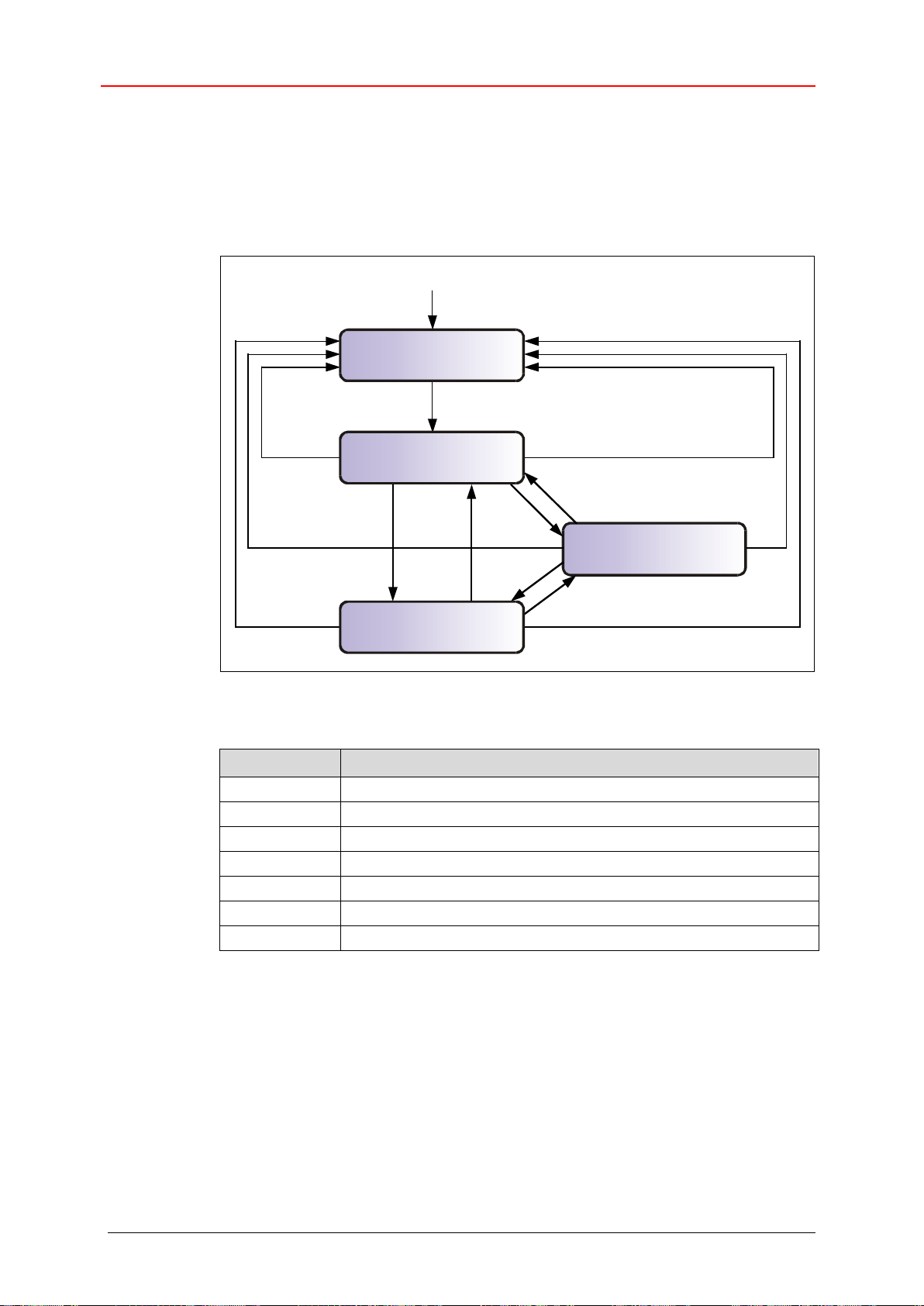
CANopen information
Stopped
(14)
(9)
(2)
(3)
(4)
(7)
(5)
(8)
(6)
Power ON or Hardware Reset
(13)
(12)
(10)
(11)
(1)
Initialization
Pre-Operational
Operational
State
Description
(1)
At Power on the initialization state is entered autonomously
(2)
Initialization finished - enter PRE-OPERATIONAL automatically
(3),(6)
Start_Remote_Node --> Operational
(4),(7)
Enter_PRE-OPERATIONAL_State --> Pre-Operational
(5),(8)
Stop_Remote_Node
(9),(10),(11)
Reset_Node
(12),(13),(14)
Reset_Communication
3.6 Network management, NMT
The network management supports a simplified Boot-Up of the net. With only one
telegram for example all devices can be switched into the Operational condition.
After Power on the measuring system is first in the "Pre-Operational" condition (2).
Figure 5: Boot-Up mechanism of the network management
TR-Electronic GmbH 2016, All Rights Reserved Printed in the Federal Republic of Germany
Page 84 of 127 TR - ECE - BA - DGB - 0128 - 01 11/20/2018

CCD
Node-ID
Byte 0
Byte 1
CCD
Meaning
State
-
At Power on the initialization state is entered autonomously
(1)
-
Initialization finished - enter PRE-OPERATIONAL automatically
(2)
0x01
Start Remote Node
Node is switched into the OPERATIONAL state and the normal
net-operation is started.
(3),(6)
0x02
Stop Remote Node
Node is switched into the STOPPED state and the
communication is stopped. An active connecting monitoring
remains active.
(5),(8)
0x80
Enter PRE-OPERATIONAL
Node is switched into the PRE-OPERATIONAL state. All
messages can be used, but no PDOs.
(4),(7)
0x81
Reset Node
Set values of the profile parameters of the object on default
values. Afterwards transition into the RESET
COMMUNICATION state.
(9),(10),
(11)
0x82
Reset Communication
Node is switched into the RESET COMMUNICATION state.
Afterwards transition into the INITIALIZATION state, first state
after Power on.
(12),(13),
(14)
3.6.1 Network management services
The network management (NMT) has the function to initialize, start, stop and monitor
nodes of a CANopen network.
NMT services are initiated by a NMT master, which identifies individual nodes (NMT
slave) about their Node-ID. A NMT message with the Node-ID 0 refers to all NMT
slaves.
The measuring system corresponds to a NMT slave.
3.6.1.1 NMT device control services
The NMT services for device control use the COB-ID 0 and get thus the highest
priority.
By the data field of the CAN message only the first two bytes are used:
The following commands are defined:
Table 4: NMT device control services
Printed in the Federal Republic of Germany TR-Electronic GmbH 2016, All Rights Reserved
11/20/2018 TR - ECE - BA - DGB - 0128 - 01 Page 85 of 127

CANopen information
Index
Description
0x100C
Guard Time [ms]
At termination of the time interval
Life Time = Guard Time x Life Time Factor [ms]
the NMT slave expects a state request by the master.
Guard Time = 0: No monitoring active
Life Time = 0: Life guarding disabled
0x100D
Life Time Factor
3.6.1.2 NMT Node / Life guarding services
With the Node/Life guarding a NMT master can detect the failure of a NMT slave
and/or a NMT slave can detect the failure of a NMT master:
Node Guarding and Life Guarding:
With these services a NMT master monitors a NMT slave
At the Node Guarding the NMT master requests the state of a NMT slave in regular
intervals. The toggle bit 27 in the “Node Guarding Protocol” toggles after each request:
Example:
0x85, 0x05, 0x85 … --> no error
0x85, 0x05, 0x05 … --> error
Additionally if the Life Guarding is active, the NMT slave requests the state of a NMT
master in regular intervals, otherwise the slave changes into the PRE-OPERATIONAL
state.
The NMT services for Node/Live guarding use the function code
1110 bin: COB-ID 0x700+Node ID.
Table 5: Parameter for NMT services
TR-Electronic GmbH 2016, All Rights Reserved Printed in the Federal Republic of Germany
Page 86 of 127 TR - ECE - BA - DGB - 0128 - 01 11/20/2018

3.7 Layer setting services (LSS) and protocols
The LSS-services and protocols, documented in CiA DS-305 V3.0, are used to inquire
or to change the settings of several parameters of the data link layer and application
layer of a LSS slave by a LSS master via the CAN network.
Following parameters are supported:
- Node-ID
- Baud rate
- LSS address compliant to the identity object (1018h)
Access to the LSS slave is made thereby by its LSS address, consisting of:
- Vendor-ID
- Product-Code
- Revision-No. and
- Serial-No.
The measuring system supports the following services:
Switch state services
● Switch state selective
● Switch state global
Configuration services
● Configure Node-ID
● Configure bit timing parameters
● Activate bit timing parameters
● Store configured parameters
Inquiry services
● Inquire LSS address
● Inquire Node-ID
Identification services
● LSS identify remote slave
● LSS identify slave
● LSS identify non-configured remote slave
● LSS identify non-configured slave
Printed in the Federal Republic of Germany TR-Electronic GmbH 2016, All Rights Reserved
11/20/2018 TR - ECE - BA - DGB - 0128 - 01 Page 87 of 127

CANopen information
Services
LSS Waiting
LSS Configuration
Switch state global
Yes
Yes
Switch state selective
Yes
No
Activate bit timing parameters
No
Yes
Configure bit timing parameters
No
Yes
Configure Node-ID
No
Yes
Store configured parameters
No
Yes
Inquire LSS address
No
Yes
Inquire Node-ID
No
Yes
LSS identify remote slave
Yes
Yes
LSS identify slave
Yes
Yes
LSS identify non-configured remote slave
Yes
Yes
LSS identify non-configured slave
Yes
Yes
3.7.1 Finite state automaton, FSA
The FSA corresponds to a state machine and defines the behavior of a LSS slave.
The state machine is controlled by LSS COBs produced by the LSS master, or NMT
COBs produced by the NMT master, or local NMT state transitions.
The LSS FSA supports the following states:
(0) Initial: Pseudo state, indicating the activation of the FSA
(1) LSS waiting: In this state, all services are supported as defined below
(2) LSS configuration: In this state, all services are supported as defined below
(3) Final: Pseudo state, indicating the deactivation of the FSA
Figure 6: LSS FSA state machine
State behavior of the supported services
TR-Electronic GmbH 2016, All Rights Reserved Printed in the Federal Republic of Germany
Page 88 of 127 TR - ECE - BA - DGB - 0128 - 01 11/20/2018
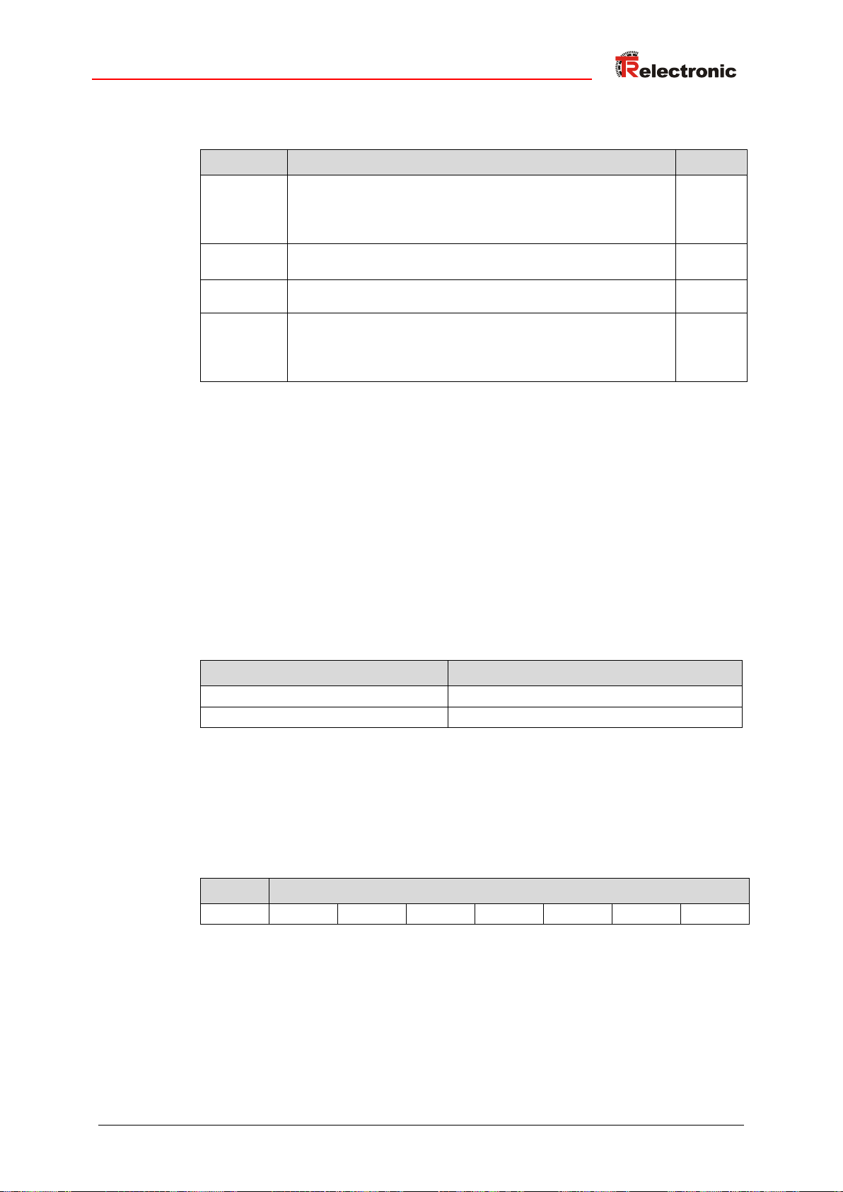
Transition
Events
Actions
1
Automatic transition after initial entry into either NMT
PREOPERATIONAL state, or NMT STOPPED state, or
NMT RESET COMMUNICATION state with Node-ID
equals FFh.
none
2
LSS switch state global command with parameter
'configuration switch' or 'switch state selective' command.
none
3
LSS switch state global command with parameter
'waiting switch'.
none
4
Automatic transition if invalid Node-ID has been changed
and the new Node-ID has been successfully stored in nonvolatile memory AND state switch to LSS waiting was
commanded.
none
COB-ID
Meaning
0x7E4
LSS slave LSS master
0x7E5
LSS master LSS slave
CS
Data
Byte 0
Byte 1
Byte 2
Byte 3
Byte 4
Byte 5
Byte 6
Byte 7
LSS FSA state transitions
Once the LSS FSA is entered further state transitions in the NMT FSA from NMT
PRE-OPERATIONAL to NMT STOPPED state and vice versa does not lead to reentering the LSS FSA.
3.7.2 Transmission of LSS services
By means of LSS services, the LSS master requests services to be performed by the
LSS slave. Communication between LSS master and LSS slave is made by means of
implemented LSS protocols.
Similar as in the case of SDO transmitting, also here two COB-IDs for sending and
receiving are used:
Table 6: COB-IDs for Layer Setting Services (LSS)
3.7.2.1 LSS message format
The data field with max. 8 byte length of a CAN message is used by a LSS service as
follows:
Table 7: LSS message
Byte 0 contains the Command-Specifier (CS), afterwards 7 byte data are following.
Printed in the Federal Republic of Germany TR-Electronic GmbH 2016, All Rights Reserved
11/20/2018 TR - ECE - BA - DGB - 0128 - 01 Page 89 of 127

CANopen information
0 1 2 3 4 5 6
7
COB-ID
CS
Mode
Reserved by CiA
0x7E5
0x04
0 = waiting mode
1 = configuration mode
0 1 2 3 4 5 6
7
COB-ID
CS
Vendor-ID (≙Index 1018h:01)
Reserved by CiA
0x7E5
0x40
LSB
MSB
0 1 2 3 4 5 6
7
COB-ID
CS
Product-Code (≙Index 1018h:02)
Reserved by CiA
0x7E5
0x41
LSB
MSB
0 1 2 3 4 5 6
7
COB-ID
CS
Revision-No. (≙Index 1018h:03)
Reserved by CiA
0x7E5
0x42
LSB
MSB
0 1 2 3 4 5 6
7
COB-ID
CS
Serial-No. (≙Index 1018h:04)
Reserved by CiA
0x7E5
0x43
LSB
MSB
0 1 2 3 4 5 6
7
COB-ID
CS
Reserved by CiA
0x7E4
0x44
3.7.3 Switch mode protocols
3.7.3.1 Switch state global protocol
The given protocol has implemented the Switch state global service and
controls the LSS state machine of the LSS slave. By means of the LSS master all LSS
slaves in the network can be switched into the LSS waiting or LSS configuration
state.
LSS-Master --> LSS-Slave
3.7.3.2 Switch state selective protocol
The given protocol has implemented the Switch state selective service and
controls the LSS state machine of the LSS slave. By means of the LSS master only this
LSS slave in the network can be switched into the LSS configuration state, whose
LSS address attributes equals the LSS address.
LSS-Master --> LSS-Slave
LSS-Slave --> LSS-Master
TR-Electronic GmbH 2016, All Rights Reserved Printed in the Federal Republic of Germany
Page 90 of 127 TR - ECE - BA - DGB - 0128 - 01 11/20/2018

0 1 2 3 4 5 6
7
COB-ID
CS
Node-ID
Reserved by CiA
0x7E5
0x11
0x01…0x7F
0 1 2 3 4 5 6
7
COB-ID
CS
Error Code
Spec. Error
Reserved by CiA
0x7E4
0x11
3.7.4 Configuration protocols
3.7.4.1 Configure Node-ID protocol
The given protocol has implemented the Configure Node-ID service. By means
of the LSS master the Node-ID of a single LSS slave in the network can be configured.
Only one device is to be switched into LSS configuration state. For storage of the
new Node-ID the Store configuration protocol must be transmitted to the LSS
slave. To activate the new Node-ID the NMT service Reset Communication (0x82)
must be called.
LSS-Master --> LSS-Slave
LSS-Slave --> LSS-Master
Node-ID
1…127: valid addresses
Error Code
0: Protocol successfully completed
1: Node-ID out of range, 1…127
2…254: reserved
255: application specific error occurred
Specific Error
if Error Code = 255 --> application specific error occurred,
otherwise reserved by CiA
Printed in the Federal Republic of Germany TR-Electronic GmbH 2016, All Rights Reserved
11/20/2018 TR - ECE - BA - DGB - 0128 - 01 Page 91 of 127

CANopen information
0 1 2 3 4 5 6
7
COB-ID
CS
Table Selector
Table Index
Reserved by CiA
0x7E5
0x13
0
0x00…0x07
0 1 2 3 4 5 6
7
COB-ID
CS
Error Code
Spec. Error
Reserved by CiA
0x7E4
0x13
3.7.4.2 Configure bit timing parameters protocol
The given protocol has implemented the Configure bit timing parameters
service. By means of the LSS master the Baud rate of a single LSS slave in the
network can be configured. Only one device is to be switched into
LSS configuration state. For storage of the new Baud rate the
Store configuration protocol must be transmitted to the LSS slave.
LSS-Master --> LSS-Slave
LSS-Slave --> LSS-Master
Table Selector
0: Standard CiA Baud rate table
Table Index
0: 1 Mbit/s
1: 800 kbit/s
2: 500 kbit/s
3: 250 kbit/s
4: 125 kbit/s
6: 50 kbit/s
7: 20 kbit/s
8: 10 kbit/s
Error Code
0: Protocol successfully completed
1: selected Baud rate not supported
2…254: reserved
255: application specific error occurred
Specific Error
if Error Code = 255 --> application specific error occurred,
otherwise reserved by CiA
TR-Electronic GmbH 2016, All Rights Reserved Printed in the Federal Republic of Germany
Page 92 of 127 TR - ECE - BA - DGB - 0128 - 01 11/20/2018

0 1 2 3 4 5 6
7
COB-ID
CS
Switch Delay [ms]
Reserved by CiA
0x7E5
0x15
LSB
MSB
0 1 2 3 4 5 6
7
COB-ID
CS
Reserved by CiA
0x7E5
0x17
0 1 2 3 4 5 6
7
COB-ID
CS
Error Code
Spec. Error
Reserved by CiA
0x7E4
0x17
3.7.4.3 Activate bit timing parameters protocol
The given protocol has implemented the Activate bit timing parameters
service. The protocol activates the Baud rate which was configured about the
Configure bit timing parameters protocol and is performed with all LSS
slaves in the network which are in the state LSS configuration.
LSS-Master --> LSS-Slave
Switch Delay
The parameter Switch Delay defines the length of two delay periods (D1, D2)
with equal length. These are necessary to avoid operating the bus with differing
Baud rate parameters.
After the time D1 and an individual processing duration, the switching internally in
the LSS slave is performed. After the time D2 the LSS slave responses with CANmessages and the new configured Baud rate.
It is necessary:
Switch Delay > longest occurring processing duration of a LSS slave
3.7.4.4 Store configuration protocol
The given protocol has implemented the Store configuration service. By
means of the LSS master the configured parameters of a single LSS slave in the
network can be stored into the non-volatile memory. Only one device is to be switched
into LSS configuration state.
LSS-Master --> LSS-Slave
LSS-Slave --> LSS-Master
Error Code
0: Protocol successfully completed
1: Store configuration not supported
2: Storage media access error
3…254: reserved
255: application specific error occurred
Specific Error
if Error Code = 255 --> application specific error occurred,
otherwise reserved by CiA
Printed in the Federal Republic of Germany TR-Electronic GmbH 2016, All Rights Reserved
11/20/2018 TR - ECE - BA - DGB - 0128 - 01 Page 93 of 127

CANopen information
0 1 2 3 4 5 6
7
COB-ID
CS
Reserved by CiA
0x7E5
0x5A
0 1 2 3 4 5 6
7
COB-ID
CS
Vendor-ID (≙Index 1018h:01)
Reserved by CiA
0x7E4
0x5A
LSB
MSB
0 1 2 3 4 5 6
7
COB-ID
CS
Reserved by CiA
0x7E5
0x5B
0 1 2 3 4 5 6
7
COB-ID
CS
Product-Code (≙Index 1018h:02)
Reserved by CiA
0x7E4
0x5B
LSB
MSB
3.7.5 Inquire LSS address protocols
3.7.5.1 Inquire identity Vendor-ID protocol
The given protocol has implemented the Inquire LSS address service. By
means of the LSS master the Vendor-ID of a single LSS slave in the network can be
read-out. Only one device is to be switched into LSS configuration state.
LSS-Master --> LSS-Slave
LSS-Slave --> LSS-Master
3.7.5.2 Inquire identity Product-Code protocol
The given protocol has implemented the Inquire LSS address service. By
means of the LSS master the Product-Code of a single LSS slave in the network can
be read-out. Only one device is to be switched into LSS configuration state.
LSS-Master --> LSS-Slave
LSS-Slave --> LSS-Master
TR-Electronic GmbH 2016, All Rights Reserved Printed in the Federal Republic of Germany
Page 94 of 127 TR - ECE - BA - DGB - 0128 - 01 11/20/2018

0 1 2 3 4 5 6
7
COB-ID
CS
Reserved by CiA
0x7E5
0x5C
0 1 2 3 4 5 6
7
COB-ID
CS
Revision-No. (≙Index 1018h:03)
Reserved by CiA
0x7E4
0x5C
LSB
MSB
0 1 2 3 4 5 6
7
COB-ID
CS
Reserved by CiA
0x7E5
0x5D
0 1 2 3 4 5 6
7
COB-ID
CS
Serial-No. (≙Index 1018h:04)
Reserved by CiA
0x7E5
0x5D
LSB
MSB
3.7.5.3 Inquire identity Revision-Number protocol
The given protocol has implemented the Inquire LSS address service. By
means of the LSS master the Revision-No. of a single LSS slave in the network can
be read-out. Only one device is to be switched into LSS configuration state.
LSS-Master --> LSS-Slave
LSS-Slave --> LSS-Master
3.7.5.4 Inquire identity Serial-Number protocol
The given protocol has implemented the Inquire LSS address service. By
means of the LSS master the Serial-No. of a single LSS slave in the network can be
read-out. Only one device is to be switched into LSS configuration state.
LSS-Master --> LSS-Slave
LSS-Slave --> LSS-Master
Printed in the Federal Republic of Germany TR-Electronic GmbH 2016, All Rights Reserved
11/20/2018 TR - ECE - BA - DGB - 0128 - 01 Page 95 of 127

CANopen information
0 1 2 3 4 5 6
7
COB-ID
CS
Reserved by CiA
0x7E5
0x5E
0 1 2 3 4 5 6
7
COB-ID
CS
Node-ID
Reserved by CiA
0x7E4
0x5E
0x01…0x7F
3.7.6 Inquire Node-ID protocol
The given protocol has implemented the Inquire Node-ID service. By means of
the LSS master the Node-ID of a single LSS slave in the network can be read-out.
Only one device is to be switched into LSS configuration state.
LSS-Master --> LSS-Slave
LSS-Slave --> LSS-Master
Node-ID
Corresponds the Node-ID of the selected device. If the Node-ID currently was
changed by means of the Configure Node-ID service, the original Node-ID
is reported. Only after execution of the NMT service Reset Communication
(0x82) the actual Node-ID is reported.
TR-Electronic GmbH 2016, All Rights Reserved Printed in the Federal Republic of Germany
Page 96 of 127 TR - ECE - BA - DGB - 0128 - 01 11/20/2018

0 1 2 3 4 5 6
7
COB-ID
CS
Vendor-ID (≙Index 1018h:01)
Reserved by CiA
0x7E5
0x46
LSB
MSB
0 1 2 3 4 5 6
7
COB-ID
CS
Product-Code (≙Index 1018h:02)
Reserved by CiA
0x7E5
0x47
LSB
MSB
0 1 2 3 4 5 6
7
COB-ID
CS
Revision-No. LOW
Reserved by CiA
0x7E5
0x48
LSB
MSB
0 1 2 3 4 5 6
7
COB-ID
CS
Revision-No. HIGH
Reserved by CiA
0x7E5
0x49
LSB
MSB
0 1 2 3 4 5 6
7
COB-ID
CS
Serial-No. LOW
Reserved by CiA
0x7E5
0x4A
LSB
MSB
0 1 2 3 4 5 6
7
COB-ID
CS
Serial-No. HIGH
Reserved by CiA
0x7E5
0x4B
LSB
MSB
0 1 2 3 4 5 6
7
COB-ID
CS
Reserved by CiA
0x7E4
0x4F
3.7.7 Identification protocols
3.7.7.1 LSS identify remote slave protocol
The given protocol has implemented the LSS identify remote slave service.
By means of the LSS master LSS slaves in the network can be identified within a
certain range. All LSS slaves with matching Vendor-ID, Product-Code, Revision-No.
Range and Serial-No. Range, response with the LSS identify slave protocol.
LSS-Master --> LSS-Slave
3.7.7.2 LSS identify slave protocol
The given protocol has implemented the LSS identify slave service. All LSS
slaves with matching LSS attributes given in the LSS identify remote slave
protocol, response with this protocol.
LSS-Slave --> LSS-Master
Printed in the Federal Republic of Germany TR-Electronic GmbH 2016, All Rights Reserved
11/20/2018 TR - ECE - BA - DGB - 0128 - 01 Page 97 of 127

CANopen information
0 1 2 3 4 5 6
7
COB-ID
CS
Reserved by CiA
0x7E5
0x4C
0 1 2 3 4 5 6
7
COB-ID
CS
Reserved by CiA
0x7E4
0x50
3.7.7.3 LSS identify non-configured remote slave protocol
The given protocol has implemented the LSS identify non-configured
remote slave service. By means of the LSS master all non-configured LSS
slaves (Node-ID = FFh) in the network are identified. The relevant LSS slaves
response with the LSS identify non-configured slave protocol.
LSS-Master --> LSS-Slave
3.7.7.4 LSS identify non-configured slave protocol
The given protocol has implemented the LSS identify non-configured slave
service. After execution of the LSS identify non-configured remote
slave protocol all non-configured LSS slaves with Node-ID FFh response with
this protocol.
LSS-Slave --> LSS-Master
TR-Electronic GmbH 2016, All Rights Reserved Printed in the Federal Republic of Germany
Page 98 of 127 TR - ECE - BA - DGB - 0128 - 01 11/20/2018

3.8 Device profile
The CANopen device profiles describe the "what" of the communication. In the profiles
the meaning of the transmitted data is unequivocal and manufacturer independently
defined. So the basic functions of each device class
e.g. for encoder: CiA DS-406
can be responded uniformly. On the basis of these standardized profiles CANopen
devices can be accessed in an identical way over the bus. Therefore devices which
support the same device profile are exchangeable with each other.
You can obtain further information on CANopen from the CAN in Automation Userand Manufacturer Association:
CAN in Automation
Am Weichselgarten 26
DE-91058 Erlangen
Tel. +49-9131-69086-0
Fax +49-9131-69086-79
Website: www.can-cia.org
e-mail: headquarters@can-cia.org
Printed in the Federal Republic of Germany TR-Electronic GmbH 2016, All Rights Reserved
11/20/2018 TR - ECE - BA - DGB - 0128 - 01 Page 99 of 127
Installation / Preparation for start-up
Cable cross section
10 kbit/s
20 kbit/s
50 kbit/s
125 kbit/s
250 kbit/s
500 kbit/s
800 kbit/s
1 Mbit/s
0.25 mm2 – 0.34 mm2
5000 m
2500 m
1000 m
500 m
250 m
100 m
50 m
25 m
The
- ISO 11898,
- the recommendations of the CiA DR 303-1
(CANopen cabling and connector pin assignment)
- and other applicable standards and guidelines are to be observed to insure
safe and stable operation!
In particular, the applicable EMC directive and the shielding and grounding guidelines
must be observed!
4 Installation / Preparation for start-up
The CANopen system is wired in bus topology with terminating resistors (120 ohms) at
the beginning and at the end of the bus line. If it is possible, drop lines should be
avoided. The cable is to be implemented as shielded twisted pair cable and should
have an impedance of 120 ohms and a resistance of 70 m/m. The data transmission
is carried out about the signals CAN_H and CAN_L with a common GND as data
reference potential. Optionally also a 24 V supply voltage can be carried.
In a CANopen network max. 127 slaves can be connected. The measuring system
supports the Node-ID range from 1-127 and the Baud rates:
● 10 kbit/s
● 20 kbit/s
● 50 kbit/s
● 125 kbit/s
● 250 kbit/s
● 500 kbit/s
● 800 kbit/s
● 1 Mbit/s
The length of a CANopen network is depending on the transmission rate and is represented in the
following:
TR-Electronic GmbH 2016, All Rights Reserved Printed in the Federal Republic of Germany
Page 100 of 127 TR - ECE - BA - DGB - 0128 - 01 11/20/2018
 Loading...