


Table of Contents
Treker
4220ST & 4420ST Light Utility Vehicles
24700
700-504M
Operator’s Manual
Read the Operator’s manual entirely. When
you see this symbol, the subsequent
!
instructions and warnings are serious - follow
without exception. Your life and the lives of
others depend on it!
© Copyright 2007 Printed
Cover photo may show optional equipment not supplied
with standard unit.
8/05/08

Table of Contents
Section 1: Introduction . . . . . . . . . . . . . . . . . . 1
Safety First . . . . . . . . . . . . . . . . . . . . . . . . . . . . . . 1
Using This Manual . . . . . . . . . . . . . . . . . . . . . . . . .1
Terminology . . . . . . . . . . . . . . . . . . . . . . . . . . . .1
Definitions . . . . . . . . . . . . . . . . . . . . . . . . . . . . .1
Application . . . . . . . . . . . . . . . . . . . . . . . . . . . . . . .1
Models Covered . . . . . . . . . . . . . . . . . . . . . . . . 1
Getting Acquainted with your Treker . . . . . . . . .1
Owner Assistance . . . . . . . . . . . . . . . . . . . . . . . . . 2
Serial Number Plate . . . . . . . . . . . . . . . . . . . . . . . .2
Section 2: Important Safety Information . . . . 3
Look For The Safety Alert Symbol . . . . . . . . . . . . .3
Be Aware of Signal Words . . . . . . . . . . . . . . . . . . .3
Safe Operating Procedures . . . . . . . . . . . . . . . . . . 5
Personal Safety . . . . . . . . . . . . . . . . . . . . . . . . .5
Mechanical Safety . . . . . . . . . . . . . . . . . . . . . . . 5
Transporting Safety . . . . . . . . . . . . . . . . . . . . . . 6
Towing Safety . . . . . . . . . . . . . . . . . . . . . . . . . .7
Safe Load Capacities . . . . . . . . . . . . . . . . . . . .7
Safety Decals . . . . . . . . . . . . . . . . . . . . . . . . . . . . 8
Section 3: Pre-Delivery and Check List . . . . 13
Pre-Delivery Certificate . . . . . . . . . . . . . . . . . . . . 13
Vehicle Information . . . . . . . . . . . . . . . . . . . . . 13
Dealer Service and Inspection List . . . . . . . . . 13
Dealer Test Ride List . . . . . . . . . . . . . . . . . . . .14
Dealer Delivery To Customer List . . . . . . . . . . 14
Customer Acceptance List . . . . . . . . . . . . . . . 14
Section 4: Operating Instructions . . . . . . . . 15
Operator Responsibilities . . . . . . . . . . . . . . . . . . . 15
Pre-Start Check List . . . . . . . . . . . . . . . . . . . .15
General Operation . . . . . . . . . . . . . . . . . . . . . . . . 15
Indicating Lights and Gauges . . . . . . . . . . . . . . .16
Switches . . . . . . . . . . . . . . . . . . . . . . . . . . . . . . . 16
Choke . . . . . . . . . . . . . . . . . . . . . . . . . . . . . . . . . 17
Floor Pedals . . . . . . . . . . . . . . . . . . . . . . . . . . . . . 17
Shift Selector and Park Brake . . . . . . . . . . . . . . . 17
Fuel Gauge . . . . . . . . . . . . . . . . . . . . . . . . . . . . . 18
Seat Belts . . . . . . . . . . . . . . . . . . . . . . . . . . . . . . 18
Cup Holders . . . . . . . . . . . . . . . . . . . . . . . . . . . . . 18
Glove Box Enclosure . . . . . . . . . . . . . . . . . . . . . . 19
Cargo Box / Flat Bed Set-Up . . . . . . . . . . . . . . . . 19
Towing . . . . . . . . . . . . . . . . . . . . . . . . . . . . . . . . .20
Engine Performance . . . . . . . . . . . . . . . . . . . . . . 20
Fuel Quality . . . . . . . . . . . . . . . . . . . . . . . . . . . 20
Incomplete Combustion . . . . . . . . . . . . . . . . . . 20
Cold Weather Operation . . . . . . . . . . . . . . . . . 20
Traveling Tips From the Trail Masters . . . . . . . . . . 21
Section 5: Options and Accessories . . . . . . . 23
Treker Options . . . . . . . . . . . . . . . . . . . . . . . . . . .23
Front Bumper . . . . . . . . . . . . . . . . . . . . . . . . . .23
Heavy Duty Brush Guard . . . . . . . . . . . . . . . . .23
Tires . . . . . . . . . . . . . . . . . . . . . . . . . . . . . . . .23
Treker Accessories . . . . . . . . . . . . . . . . . . . . . . . .24
Section 6: Maintenance . . . . . . . . . . . . . . . . . 25
General Maintenance . . . . . . . . . . . . . . . . . . . . . .25
Securing Vehicle for Maintenance . . . . . . . . . . . .25
Torque Values . . . . . . . . . . . . . . . . . . . . . . . . . . .25
Tire Maintenance . . . . . . . . . . . . . . . . . . . . . . . . .25
Jacking the Vehicle . . . . . . . . . . . . . . . . . . . . . . . .26
Shock Absorber Adjustment . . . . . . . . . . . . . . . . .26
Electrical System . . . . . . . . . . . . . . . . . . . . . . . . .27
Battery . . . . . . . . . . . . . . . . . . . . . . . . . . . . . . . . .27
Adding Water to the Battery . . . . . . . . . . . . . . . . .28
Charging the Battery . . . . . . . . . . . . . . . . . . . . . .28
Jump Starting the Battery . . . . . . . . . . . . . . . . . .28
Fuel System . . . . . . . . . . . . . . . . . . . . . . . . . . . . .29
Engine Maintenance . . . . . . . . . . . . . . . . . . . . . .30
General Information . . . . . . . . . . . . . . . . . . . . .30
High Altitude Carburetor Kit . . . . . . . . . . . . . . .30
Drive Belt Replacement . . . . . . . . . . . . . . . . . . . .31
Driven Pulley Maintenance . . . . . . . . . . . . . . . . . .31
Engine Air Filter Maintenance . . . . . . . . . . . . . . .32
Engine Air Filter Handling . . . . . . . . . . . . . . . . . .32
CVT Snorkel Filter Maintenance . . . . . . . . . . . . .33
Exhaust System . . . . . . . . . . . . . . . . . . . . . . . . . .34
Spark Arrester . . . . . . . . . . . . . . . . . . . . . . . . .34
Park Brake Adjustment . . . . . . . . . . . . . . . . . . . . .35
Maintenance Schedule . . . . . . . . . . . . . . . . . . . . .36
Section 7: Lubrication . . . . . . . . . . . . . . . . . .37
Engine Oil . . . . . . . . . . . . . . . . . . . . . . . . . . . . . .37
Case Oil . . . . . . . . . . . . . . . . . . . . . . . . . . . . . . . .39
Rear Trans-axle Case . . . . . . . . . . . . . . . . . . .39
Center Transfer Case . . . . . . . . . . . . . . . . . . .40
Front Differential Case . . . . . . . . . . . . . . . . . . .40
Brake Fluid . . . . . . . . . . . . . . . . . . . . . . . . . . . . . .41
Section 8: Seasonal Storage . . . . . . . . . . . . . 42
Section 9: Body Repair . . . . . . . . . . . . . . . . . 43
Section 10: Specifications and Capacities . . 45
Section 11: Features and Benefits . . . . . . . . 46
Section 12: Troubleshooting . . . . . . . . . . . . . 47
Section 13: Appendix . . . . . . . . . . . . . . . . . . . 51
Torque Values Chart . . . . . . . . . . . . . . . . . . . . . .51
Tire Inflation Chart . . . . . . . . . . . . . . . . . . . . . . . .51
Notes . . . . . . . . . . . . . . . . . . . . . . . . . . . . . . . . . .52
Land Pride Limited Warranty . . . . . . . . . . . . . . . .53
© Copyright 2007 All rights Reserved
LandPrideprovidesthispublication “as is” withoutwarrantyofanykind,either expressed or implied.While every precaution hasbeen taken in thepreparationof this manual,
Land Pride assumes no responsibility for errors or omissions. Neither is any liability assumed for damages resulting from the use of the information contained herein. Land
Pride reserves the right to revise and improve its products as it sees fit. This publication describes the state of this product at the time of its publication, and may not reflect
the product in the future. The illustrations in this manual are not intended for safe and proper assembly or disassembly of equipment. The illustrations are intended for
ordering parts only.
All other brands and product names are trademarks or registered trademarks of their respective holders.
Weather Pro G is a registered trademark of Spartech Plastic
Land Pride is a registered trademark.
Printed in the United States of America.
4220ST & 4420ST Light Utility Vehicles 700-504M
8/05/08

Section 1: Introduction
Section 1: Introduction
Table of Contents
Land Pr ide welcomes you to its growing familyof new
product owners. Treker series trucks are light utility
vehicles that have been designed with care and built by
skilled workers using quality materials. Proper set-up,
maintenance and safe operating practices will help you
get years of satisfactory use from this vehicle.
Safety First
Land Pr ide is fully aware of the need for safe operating
procedures around all of our equipment. Wehope you
will make a sincere effort to put safety above all other
priorities. The Trekers are designed and built for work,
recreation and enjoyment; however, improper and
irresponsible operation could result in serious injury or
death. Since this is an off-road vehicle, operators will
seldom see road safety and warning signs they are
accustomed to seeing on highways and public streets.
This places additional responsibility on the driver to
operatethisvehiclewell withinsafeoperationallimits and
capabilities of the unit.
Thismanualhas beenprepared toinstr uct youin the safe
and responsible operation of your Treker. Please read
and abide by all safety alert information about this
vehicle.If you do not understand anypart of this manual,
contact your local dealer for additional information and
clarification. As the operator of this piece of equipment,
you are in complete control. Only you can prevent an
accident from happening!
Using This Manual
Prior to any vehicle operation it is absolutely essential
•
that you read and comprehend each section in this
manualto develop an understanding of your vehicle and
safetypractices. After reviewing this manual,store itin a
dry and easily accessible place for future reference.
• TheOperator’s Section is designed to help familiarize
you with safety, assembly, operation, adjustments,
troubleshooting and maintenance. Read this manual
and follow recommendations to help ensure safe and
efficient operation.
• Theinformation contained within this manual was
current at the time of printing. Some parts may change
slightly to assure you of the best performance.
• Toordera new Operator’s orParts Manual contact your
authorized dealer. Manuals can also be downloaded,
free-of-charge from our website at www.landpride.com
orprinted fromthe LandPride Service& Support Center
by your dealer.
Terminology
Right-hand and left-hand as used in this manual are
determined by facing the direction the vehicle will travel
while in use unless otherwise stated.
Definitions
The following terms are used throughout this manual.
IMPORTANT: A special pointof inf ormation related to
its preceding topic. Land Pride’s intention is that this
information should be read and noted before
continuing.
NOTE:A special point of informationthat the operator
must be aware of before continuing.
Application
Models Covered
4220ST 4x2 and 4420ST 4x4
Getting Acquainted with your Treker
TheTreker line of light utility vehiclesisdesigned byLand
Pride exclusivelyfor off-road use. They are not designed
for, nor arethey properly equippedto be safely operated
orlicensed foruseon publicstreetsand highways.These
vehicles are designed to carry two tothree peopleand a
limited amount of gear or cargo comfortably and safely
over rough or difficult off road terrain.
The wide stance ST series is designed to carry three
passengerson the bench seat and 900 lbs. of cargo in its
15.9cu-ft. capacitydumping cargoboxfor a total payload
capacity of 1,300 lbs.The wide stance, longwheelbase,
and high payload make the ST series Trekers a strong
and stable workhorse for ranches, farms, and
construction sites.
The 4220ST series (4x2) is equipped with two wheel
traction drive and the 4420ST series (4x4) is equipped
with four wheel traction dr ive. Both series have an
automotive steering wheel with easy handling rack-andpinion steer ing, four wheeled independent suspension,
McPherson Str uts, large diameter hi-flotation tires, and
high center-frame ground clearances that add up to
excellent stability and smooth ride over tough terrain.
The 4420ST series feature our Command Track four
wheel dr ive system with over-running clutches on the
front differential for unexcelled traction, easy handling
and minimal disturbance to the turf. These models also
feature Auto-Lock rear differentialswith over-running
clutches and sealed torque converters for absolute
maximumtractioncapability inwet or slippery conditions.
Seat belts for two passengers are standard. An
additional seat belt may be added for the center third
person.
8/05/08
4220ST & 4420ST Light Utility Vehicles 700-504M
1
Section 1: Introduction
Table of Contents
Driving a Treker is as easy as driving a pickup with an
automatic transmission. A simple forward and reverse
shifter provides direction control. A neutral start feature
and keyed 12-volt electronic ignition make for safe and
easy starting. We have even provided a manual choke
controlwith spring-loadedreturnforquickercold weather
starting. The infinitely variabletorque converter drive
system means there is no clutching; you just shift into
either forward or reverseand step on the throttle pedal to
go at speeds up to 25 mph. All Trekers are powered by
highly reliableand proven 20 hp.Honda engines that are
EPA certified and meet Califor nia Air Resources Board
(CARB) certification standards.
Braking is accomplished by simply depressing thebrake
pedal located on the floorboard. This activates the rear
hydraulic drum brakesand front mounted disc brakes.
The par k brake is incorporated into the dash-mounted
shifter so when you put the vehicle in park you
simultaneously set the park brake. All modelscome with
a very strong 4-post accessory bar that provides extra
protection against low hanging limbs and brush as well
as providing a mounting systemfor accessories suchas
windshields, canopy tops, and weather enclosures.The
4-post accessory bar also provides a mounting base for
accessories such as cargo racks, gun and bow racks,
back screens, tree stands, and camping or fishing gear
and tool holders. Astandard rearreceiver enables quick
installation of a hitchto pull smalltrailers full ofsupplies,
tools, gear, or game.
Owner Assistance
The safety video should be viewedby the owner and the
Warranty Registration card should be filled out by the
dealer at the time of purchase. The owner should also
receive a copy of the safety video upon purchasing the
vehicle as well as have participated in a shor t drivers
training course with the dealer. This information is
necessary to provide you with quality customer service.
The parts on your Treker Light Utility Vehicle have been
specially designed and should only be replaced with
genuine Land Pride parts.
If customer service or repair parts are required contact a
Land Pride vehicle dealer. They have trainedpersonnel,
genuine repair parts and equipment specially designed
to repair Land Pride products.
Serial Number Plate
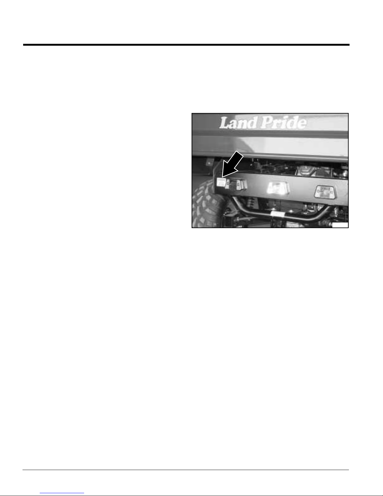
Refer to Figure 1:
Always use serial and model number when ordering
parts from your Land Pride dealer. The serial-number
plate is located on the driver’sside just left of the rear tail
light as shown in figure 1 below.
21121
Serial Number Plate
Figure 1
Record your vehicle model number(4220ST or 4420ST)
and ser ial number here for quick reference:
Model Number:__________________________
Serial Number: ___________________________
YourLandPride dealer wantsyou to be satisfied withyour
new vehicle. If you do not understand any part of this
manual or are not satisfied with the service received,
please take the following actions.
1. Discuss the matter with your dealership service
manager.Make surethey are aware of any problems
so they can assist you.
2. If you are still unsatisfied, seek out the owner or
general manager of the dealership.
3. For further assistance write to:
Product Support
Land Pride Service Department
1525 East North Street
P.O. Box 5060
Salina, Ks. 67402-5060
4220ST & 4420ST Light Utility Vehicles 700-504M
2
E-mail address
lpservicedept@landpride.com
8/05/08
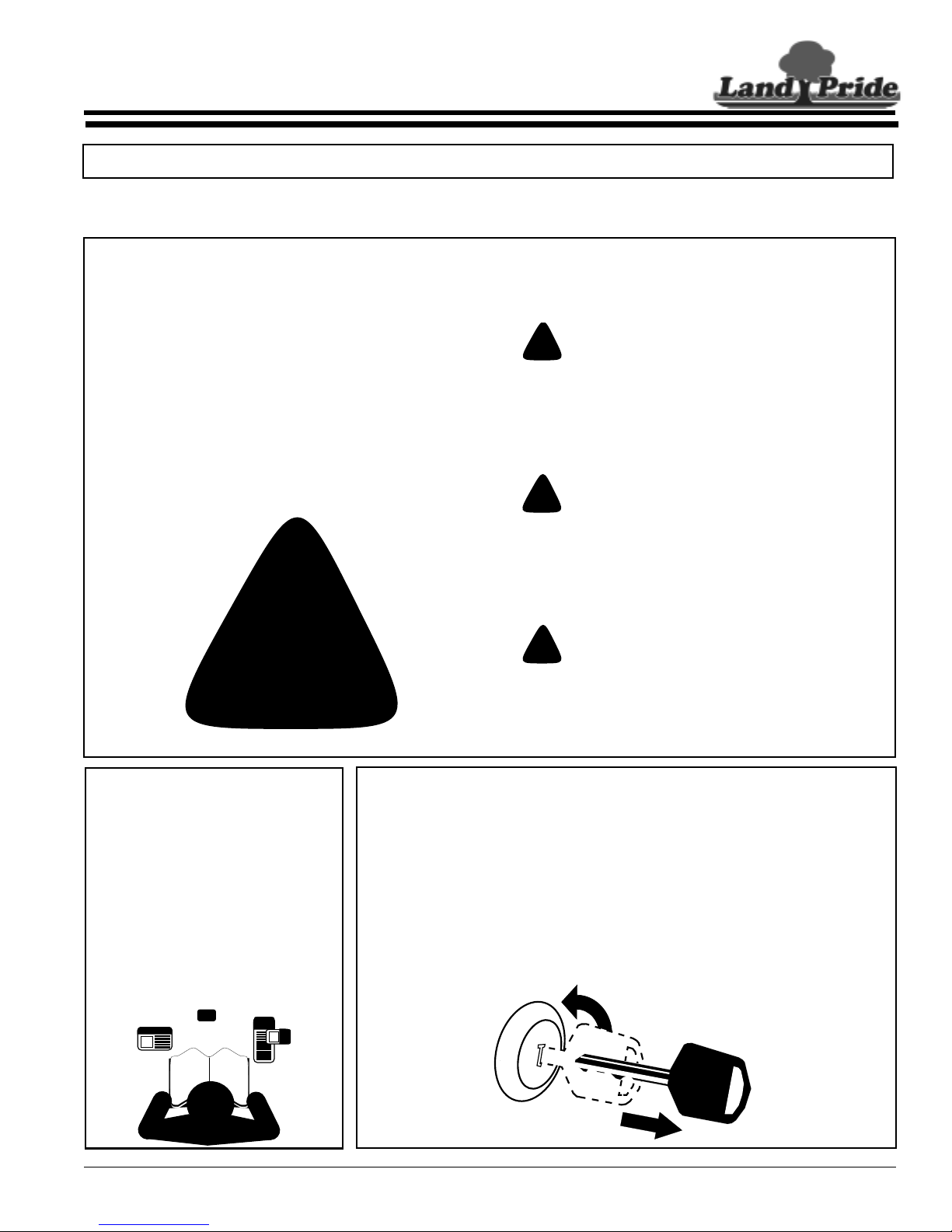
Table of Contents
Section 2: Important Safety Information
Section 2: Important Safety Information
IMPORTANT: Read and understand all pages in this manual thoroughly before operating your vehicle.
These are common practices that may or may not be applicable to the products described in
this manual.
Look For The Safety Alert
Symbol
TheSAFETY ALERTSYMBOL indicates there is
a potential hazard to personal safety involved
andextrasafetyprecaution must be taken.When
you see this symbol, be alert and carefully read
the message that follows it. In addition to design
and configuration of equipment, hazard control
and accident prevention are dependent upon the
awareness, concern, prudence and proper
training of personnel involved in the operation,
transport, maintenance and storage of
equipment.
!
Be Aware of Signal Words
A signal words designate a degree or level of
hazard ser iousness. The signal words are:
!
DANGER
DANGERindicates an imminently hazardoussituation
which, if not avoided, will result in serious or death
injury.This signal word is limited to the most extreme
situations, typically for vehicle components that, for
functional purposes, cannot be guarded.
!
WARNING
WARNINGindicates a potentially hazardoussituation
which, if not avoided, could result in death or serious
injury, and includes hazards that are exposed when
guards are removed. It may also be used to alert
against unsafe practices.
!
CAUTION
CAUTIONindicates a potentially hazardous situation
which, if not avoided, may resultin minor or moderate
injury. It may also be used to alert against unsafe
practices.
For Your Protection
▲ Thoroughly read and understand
the instructions given in this
manual before operation. Refer to
the “Safety Label” section, read all
instructions noted on the decals.
▲ Do not allow anyone to operate
this equipment who has not fully
read and comprehended this
manual and who has not been
properly trained in the safe
operation of the equipment.
8/05/08
Before Operating
▲ This Treker Light Utility Vehicle is
not to be driven on public roads.
▲ Do not operate this vehicle under
the influence of alcohol or drugs.
▲ Always inspect the vehicle before
operating it. See "Pre-Start Check
List" on page 15.
OFF
4220ST & 4420ST Light Utility Vehicles 700-504M
▲ Do not operate this machine
unless all safety shields are in
place and all badly worn, broken or
missing parts have been properly
replaced.
▲ Wear appropriate protective gear
and clothing such as safety
helmet, goggles, gloves, coveralls,
etc., when conditions warrant.
▲ No driver under age of 16.
3
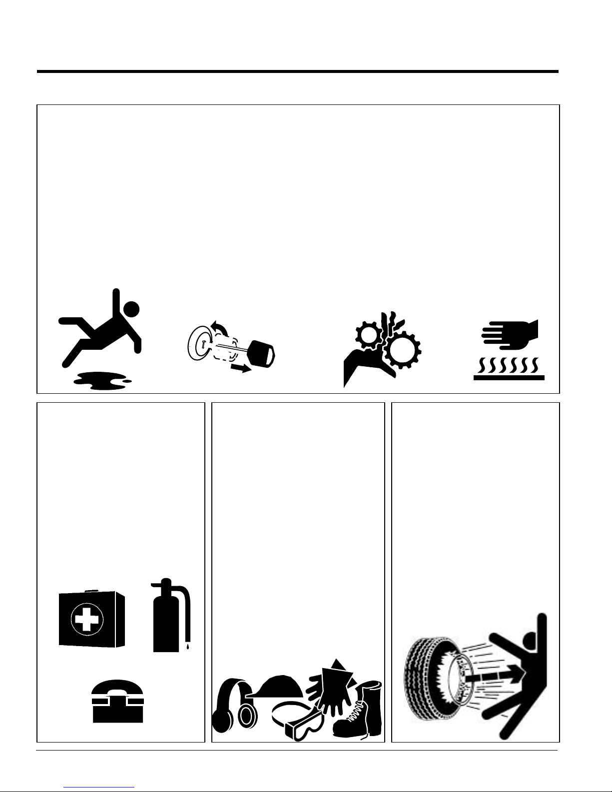
Table of Contents
Section 2: Important Safety Information
These are common practices that may or may not be applicable to the products described in
this manual.
Practice Safe
Maintenance
▲ Understand procedure before
doing work. Use proper tools and
equipment.Refer to this manual for
additional information.
▲ Work in a clean, dry area.
▲ Place the vehicle in neutral, set
parking brake, turn off engine and
remove key before performing
maintenance. Chock wheels if you
must perform maintenance on a
slope.
▲ Make sure all moving parts have
stopped and all system pressure is
relieved.
▲ Allow the engine to cool completely.
▲ Disconnect battery ground cable (-)
before servicing or adjusting
electrical systems or before
welding.
OFF
▲ Inspect all parts. Make sure parts
are in good condition and installed
properly.
▲ Remove build-up of grease, oil or
debris.
▲ Remove all tools and unused parts
from the Treker before operation.
Prepare for
Emergencies
▲ Be prepared if a fire starts.
▲ Keep a first aid kit and fire
extinguisher handy.
▲ Keep emergency numbers for
doctor, ambulance, hospital and
fire department near phone.
Wear Pr otective
Equipment
▲ Wear protective clothing and
equipment.
▲ Wear clothing and equipment
appropriate for the job. Avoid
loose-fitting clothing.
▲ Because prolonged exposure to
loud noise can cause hearing
impairment or hearing loss, it is
best to wear suitable hearing
protection such as earmuffs or
earplugs.
▲ Because operating equipment
safely requires your full attention,
avoid wearing radio headphones
while operating machinery.
▲ It is the discretion of the operator
and passenger to wear Seat Belts
when available.
Tire Safety
Tire changing can be dangerous
andshould be performedbytrained
personnel using correct tools and
equipment.
▲ When inflating tires, use a clip-on
chuck and extension hose long
enough for you to stand to one
side–not in front of or over tire
assembly. Use a safety cage if
available.
▲ When removing and installing
wheels, use wheel-handling
equipment adequate for weight
involved.
911
4220ST & 4420ST Light Utility Vehicles 700-504M
4
8/05/08

Table of Contents
Section 2: Important Safety Information
Safe Operating Procedures
The safe operation of any machiner y is a bigconcern to
allconsumers. YourTreker has been designedwith many
built-in safety features. However, noone should operate
this vehicle beforecarefully reading this Operator’s
Manual. Also read all instructions noted on the safety
decals.
Personal Safety
▲ Be familiar with all functions of this vehicle.
▲ Do not allow anyone to operate this vehicle who has not
fully read and comprehended this manual and who has
not been properly trained in the safe operation of this
vehicle.
▲ Do not operate vehicle while drinking or under the
influence of alcohol or drugs.
▲ Do not allow anyone under 16 years of age to operate
this vehicle even under adult supervision.
▲ Do not run engine indoors except when starting engine
and transporting attachment in or out of a building.
Carbon monoxide gas is colorless, odorless and deadly.
▲ Operator must always use both hands on the steering
wheel.
▲ Keep all bystanders away from this vehicle during
operation. Keep children out of the operating area and
under the watchful eye of another responsible adult.
▲ Riders may, without knowing it, place their foot on the
accelerator pedal while bracing themselves against a
rough ride. This makes it impossible to slow down the
vehicle until the passenger removes his foot from the
pedal. Inform passenger to keep his foot off the
accelerator and always slow down before the ride gets
rough.
▲ Operator and passenger are responsible for deciding if
their situation warrants using seat belts if so equipped.
▲ No riders are allowed except in factory designed and
supplied seating and no more than one person in a
bucketseat and three people in a bench seat. Do not use
cargo bed for carrying people. Maximum vehicle
occupancy including driver is one person per seat
position.
▲ Operate vehicle from driver’s seat only.
▲ Do not leave vehicle unattended with engine running.
▲ Do not dismount a moving vehicle as serious injury or
death could occur.
▲ Wear snug-fitting clothing to avoid entanglement with
moving parts.
▲ Keep hands, feet, long hair, clothing and jewelry away
from moving parts and obvious pinch points to avoid
getting caught.
▲ Keep hands, arms, feet and all bodily appendages safely
inside the confines of the vehicle. Alwaysbe aware of and
avoid tree limbs and brush that have a potential of hitting
and/or poking individuals riding the vehicle. Serious body
harm could result.
▲ Some conditions may warrant extra safety gear to be
worn such as safety helmets and/or goggles.
▲ Do not touch engine, engine exhaust pipe and/or muffler
while they are hot.
▲ Avoid pinch point hazards. Cargo bed and seat platform
hinge creating pinch points.
▲ Battery fumes are explosive. A spark will ignite battery
fumes. Wear a face shield when charging or jumping a
battery. Follow all battery safety rules outlined in this
manual.
▲ Avoid battery acid spills. Do not get battery acid on eyes,
face, or other body parts. Flush eyes and other body
parts immediately with water for at least 15 minutes if
battery acid has gotten on them.
▲ When refueling use a UL approved nonmetallic container
that has no screen or filter. Set container on the ground
beforefueling to eliminate static discharge and do not use
Methanol fuel.
▲ Do not smoke or use electrical devices including cell
phones while refueling.
▲ Support this vehicle securely before working beneath.
Chock wheels to prevent vehicle from rolling.
Mechanical Safety
▲ Do not operate a vehicle with damaged or worn parts.
Repair all damages and worn parts before putting vehicle
back in to service.
▲ Never attempt to make any adjustments while engine is
running or hot. Keep clear of all rotating parts.
▲ Make sure engine surface, cooling fins and fan screen
are clean of all debris including dirt, trash and oil.
▲ Always operate vehicle with drive belt enclosure installed.
Do not leave pulleys and belts exposed.
▲ Never modify any parts on the vehicle without
authorization. Unauthorized modifications will void
warranty to all parts directly and indirectly affected by the
modification.
▲ Do not use cargo tail gate as a seat.
▲ Do not use cargo bed as a working platform.
▲ The power lift is designed todump cargo only.Do not use
it to lift other objects.
▲ Never attempt “wheelies”, jumps, or other stunts. Never
drive recklessly. Always operate your vehicle at a safe
speed that will allow you to maintain control.
▲ Do not use vehicle as an anchor device.
8/05/08
4220ST & 4420ST Light Utility Vehicles 700-504M
5

Table of Contents
Section 2: Important Safety Information
▲ Do not mount a receiver hitch type carrier platform to the
vehicle.
▲ Front bumper, brush guards and cargo box are not
designed as pusher bars. Do not attempt to push other
vehicles or implements or damage may result.
▲ Always maintain proper tire inflation. See "Tire
Maintenance" on page 25.
▲ Always disconnect negative battery terminal before
making adjustments to vehicle electrical system or
welding on this vehicle.
▲ Always check wheel lug nut torque valuestwo hours after
initial operation and two hours after each tire repair or
replacement. Routinely check lug nut torque every 100
hours of operation. See "Wheel Lug Nuts" on page 25.
▲ Do not shift trans-axle unless this vehicle is fully stopped
and engine is at idle or damage may occur.
▲ Keep safety decals clean of dirt and grime.
▲ Replace all missing, illegible, or damaged safety decals.
See list of safety decals in this manual.
Transporting Safety
!
WARNING
Most accidents with off road vehicles occur when traveling up,
down, or across the face of a slope. Refer to operation
instructions and safety video for proper operation procedures.
▲ Use extreme caution when driving through dry grass,
brush and other fire hazard materials. Never stop or park
over combustible materials. Keep grass and brush from
collecting on and around engine and muffler parts.
▲ Be aware of cargo shifting when stopping or moving.
Make sure all cargo is properly secured and tied down.
Injury could result from loose cargo.
▲ Avoid sudden stops, starts and turns.
▲ Always make sure vehicle pathway is clear of all objects
when backing up. Know location of persons around
vehicle and especially location of small children. Take
extra precautions when rear view is hindered by cargo.
▲ Do not attach an implement, trailer or other device to the
hitch that will produce negative tongue weight.
▲ Reduce speed and payload on hilly, rough, wet, slick or
unstable ground.
▲ Reduce speed when loaded with cargo. Heavycargo load
takes longer to stop.
▲ Always make turns at a speed that willmaintain control of
vehicle. Never make turns at full speed. Reduce speed
when turning empty and reduce speed even more when
turning loaded. The heavier the cargo load, the slower the
turn should be.
▲ The 4-post accessory bar is not a certified ROPS (Roll
Over Protection System). Always avoid roll-overs.
▲ Do not load 4-post accessory bar with heavy equipment.
Rollover could result from such loading.
▲ Always park on level ground, stop engine, set park brake
(see "Shift Selector and Park Brake" on page 17) and
remove ignition key before leaving vehicle. Chock tires if
condition warrants.
▲ Use extreme caution when cresting hills, approaching
blind corners, shrubs, trees or other obstructions that
might limit visibility. Proceed slowly until youare sure trail
conditions immediately ahead are safe. Use extra care
when approaching obstructions that might hide children.
▲ Be especially observant of operating area and terrain.
Watch for holes, rocks, or other hidden hazards. Do not
operate vehicle near the edge of drop-offs or banks.
▲ Keep front wheels straight when cresting hills or going
over bumps.
▲ Do not stop, start suddenly or over accelerate on hills.
Loss of control and rollover could result.
▲ Use extreme caution when descending hills, running on
loose slippery surfaces, or when towing at maximum
capacity. Towing, braking and tractive capabilities are
greatly diminished.
▲ Avoid changing direction or making sharp steering
corrections on slopes or rollover may occur.
▲ If this vehicle begins to tip when crossing a slope, turn
front wheels downhill to regain stability and control.
▲ Do not operate vehicle on slopes over 15
▲ When crossing a slope on soft terrain, turn front wheels
slightly uphill and maintain a constant speed to maintain a
straight line of travel.
▲ When descending hills or slopes apply steady pressure to
the foot brake to avoid potential of freewheeling or
runaway.
▲ Never allow vehicle to coast or free wheel in neutral or
loss of control may result.
▲ If your vehicle loses power and stops on a hill,
immediately engage foot brake and backslowly down the
hill maintaining a straight downhill line of travel. Do not
attempt to turn vehicle sideways on the hill or a rollover
could result.
▲ Never operate vehicle without good visibility and lighting.
When traveling at night always use your headlights and
reduce speed according to visibility, trail and terrain
conditions.
▲ Do not operate this vehicle on highways, public roads, or
where it may be a hazard to faster moving traffic.
▲ Exercise extreme caution when operating on or crossing
a gravel drive, walks, or roads. stay alert for hidden
hazards or traffic.
o
.
4220ST & 4420ST Light Utility Vehicles 700-504M
6
8/05/08

Table of Contents
Section 2: Important Safety Information
▲ Avoid water crossings when possible and never cross a
body of water where depth is unknown. Loss of power will
occur if drive belt becomes submerged or wet.
Unnecessary crossing of streams and waterways erodes
shore line and damages water-born habitat. If you must
cross, do it at a point where banks are not steep and
proceed at a slow and steady speed. Do not travel in
water that ishigher than the bottom wheel lug nuts. Water
higher than the bottom wheel lug nut can damage the
brake system and get the drive belt wet stalling the
vehicle. However, intermittent stream crossings where
depth of water briefly comes into contact with bottom of
floorboards is acceptable. See "Going Out on the Trail"
Note 7 on page 21.
▲ Never use vehicle for racing and never modify engine to
exceed 25 MPH vehicle speed.
Towing Safety
▲ Follow all towing instructions in this manual when towing
the Treker behind another vehicle. Do not tow the vehicle
faster than 25 MPH. See "Towing" on page 20.
▲ Beware, tow ropes, cables and chains can break when
pulling another vehicle or object causing serious injury or
death to anyone in line with the whipping action created
when they break. Never jerk when pulling, always ease
into a pull gently. Always stay clear of tow line. Never be
in line with tow line.
Safe Load Capacities
Refer to Vehicle Specifications onpage 45:
▲ Do not exceed total payload capacity of this vehicle.
▲ Do not pull a trailer or implement exceeding maximum
towing capacity and/or maximum tongue weight.
Loss of control may result.
▲ Do not exceed front cargo rack carrying capacity.
▲ Do not exceed rear cargo box payload capacity.
8/05/08
4220ST & 4420ST Light Utility Vehicles 700-504M
7

Table of Contents
Section 2: Important Safety Information
Safety Decals
Your Treker comes equipped with all safety labels in place.
They were designed to help you safely operate your implement.
Read and follow their directions.
1. Keep all safety decals clean and legible.
2. Replace all damaged or missing decals. Order new safety
decals through your Land Pride dealer.
3. Some new equipment installed during repair requires safety
labels to be affixed to the replaced component as specified
24690
by Land Pride. When ordering new parts or components,
also request corresponding safety decals.
4. Refer to this section for proper label placement. Install new
decals as follows
a. Clean area on which decal is to be placed.
b. Spray soapy water on the surface where decal is to be
placed.
c. Peel backing from decal. Press firmly on surface,
being careful not to cause air bubbles under decal.
d. Squeeze out air bubbles with edge of a credit card.
838-303C
Danger: Battery
4220ST & 4420ST Light Utility Vehicles 700-504M
8
24691
23536
818-543C
Danger: Guard Missing
838-629C
Warning: Pinch Point or Crushing Hazard
8/05/08
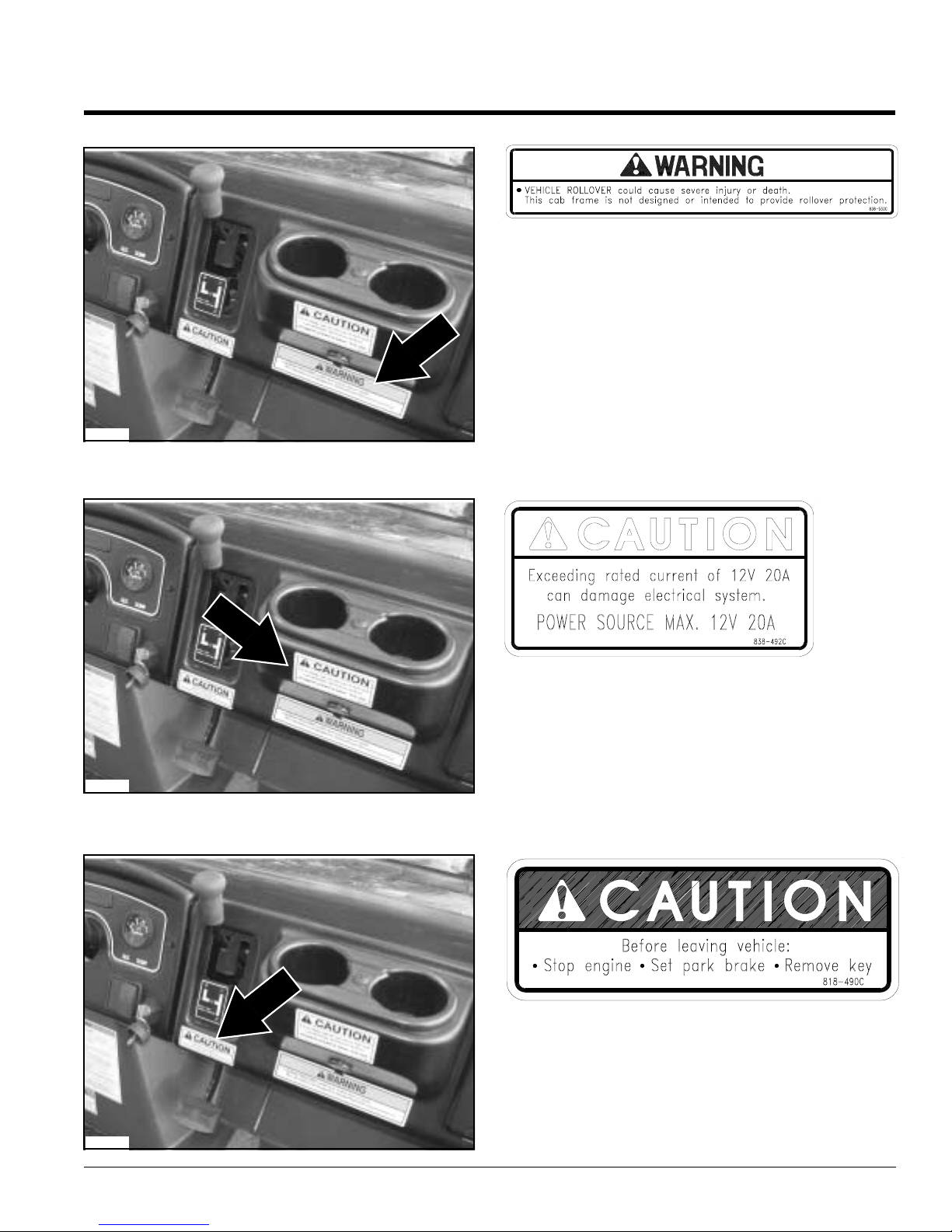
Table of Contents
Section 2: Important Safety Information
24697
838-532C
Warning: Cab Rollover Protection
24697
24697
838-492C
Caution: Maximum Power Source
838-490C
Caution: Stop Engine
8/05/08
4220ST & 4420ST Light Utility Vehicles 700-504M
9

Table of Contents
Section 2: Important Safety Information
4220ST & 4420ST Light Utility Vehicles 700-504M
10
838-486C
Warning: General Utility Vehicle
24694
8/05/08

Table of Contents
Section 2: Important Safety Information
838-570C
Vehicle Loading Capacities, 4220ST Series
24694
21147
838-663C
Vehicle Loading Capacities, 4420ST Series
838-579C
Trailer Towing Information
8/05/08
24735
838-508C
Warning: Before Filling Tank with Gasoline
4220ST & 4420ST Light Utility Vehicles 700-504M
11

Table of Contents
Section 2: Important Safety Information
21110
21110
838-491C
Warning: Improper Use
838-489C
Warning: Rollover Hazard
4220ST & 4420ST Light Utility Vehicles 700-504M
12
24695
838-444C
Danger: Muffler hot
8/05/08

Table of Contents
Section 3: Pre-Delivery and Check List
Section 3: Pre-Delivery and Check List
Each vehicle must undergo a Pre-Delivery Inspection by the Dealer. Listed below is an example of the checklist that
is included with the Warranty Registration that is to be submitted to Land Pride upon Retail Sale. The Pre-Delivery
Certificate and Warranty Registration must be submitted to Land Pride in order to activate the vehicle warranty.
Pre-Delivery Certificate
The dealer is required to complete Land Pride’s
“Certificate of Light Utility Vehicle Pre-Deliver y” form
before customer may take possession of vehicle. The
information must be filled in and check list checkedoff or
initialed by individuals performing the checks.
Dealership’sname, signatures of individualsfilling in the
form,seller’ssignature,customer’ssignature andsigning
dates are also required before the form is returned to
Land Pride. Below is a listof the information found in the
form that is required to be completed and checked off.
Vehicle Information
Model No. _________________
Date _________________
Serial No. _________________
Engine Serial No. _________________
Dealer Service and Inspection List
___Fully charge battery. Check battery voltage to verify
that it is fully charged.
___Connect negative battery cable. (Negative battery
cable is disconnected before leaving factory and is to
be disconnected after initial dealer set-up to prevent
battery discharge while setting on the dealer’s lot.)
___Check tire pressure to make sure front and rear tires
havea minimum of 7 psi. See "Tire Inflation Chart" on
page 26.
___Make sure wheellug bolts/nuts are tightened to 90
Newton meters/(65ft. lbs.).
___Check master cylinderto make sure it is filled.
___Checkengine oil levelat thedipstick. Add SAE 10W30
oil if oil is below the full mark on the dipstick. Do not
overfill.
___Check engine for correct RPM. Set to factory
specification if needed. (See page 45)
___Check Tie Rods for tightness.
___Step on footbrake to make sure there is plenty of
pedal and that brakes hold pressureand do not bleed
off. Add brake fluid and bleed brakes if required.
___Make sure seats and seatbelts areproperly fastened
to vehicle frame if so equipped.
___Make sure allsafety decalsare in place.
___Check headlights tomake sure they are working and
are properly mounted.
___Checktail lights and brakelightsto makesure theyare
working and are properly mounted.
___Inspect air cleaner element. Make certain it is clean
and in place.
___Inspect fuel tank to make sure it is properly installed
and that there are no leaks.
NOTE: Vehicles are shipped from thefactory with
about a quart of fuel in the tank
___Checkfuel levelin tank.If needed, add gasoline with a
fuel stabilizer to perform initial starting operations.
See "Fuel System" instructions onpage 29 before
adding fuel.
___Inspect fuel lines to make sure they are properly
installed and that there are no leaks.
___Check steering byexecuting a full lock to lock turn in
each direction.
___Checkpark brake to makesure itwill engage, holdand
release.
___Make sure neutral start feature is working bytrying to
start unit while shifter is located in the forward and
reversepositions.
___Check throttle controlto make sure it moves and
returns freely.
___Check choke control to make sure it moves and
returns freely.
___Check Rear Trans-axleoil level at the oil plug. Add
Land Pride special formulated gear lube noted on
page 39 if oil is low.
___Checkoverallappearanceforcleanliness and forbody
and molding damage.
.
8/05/08
4220ST & 4420ST Light Utility Vehicles 700-504M
13

Table of Contents
Section 3: Pre-Delivery and Check List
Dealer Test Ride List
___Check engine for starting, accelerating, running and
idling smoothly.
___Check steering response.There should be no free-
play.
___Checkforward, neutral and reverseshifting response.
Also check neutral start response.
___Check park brake to make sure itengages, holds and
disengages.
___Make sure rocker switches are all working.
___Make sure throttleis responsive and returns freely.
___Make sure suspensionride is satisfactory and stable.
___Make sure thereare no fuel or petroleum leaks.
___Makesure foot brake has a firm engagement and that
stopping is straight.
___Make sure thereare no bad rattles or vibrations.
Dealer Delivery To Customer List
___Warranty registration form is complete.
___Owner’s Manual has been delivered to and reviewed
by customer.
___EngineManual has been delivered to and reviewedby
customer.
___Warranty Policy limits and requirements have been
explained to customer.
___Customer has reviewed safety video.
___Location and functions of vehicle controls have been
explained.
___Fuel transportation and storage procedures have
been explained.
___Fluid fill and lubrication points have been locatedand
explained to customer.
___Customer has completed the driving course.
___Information on safetydecals have been reviewedwith
customer.
Customer Acceptance List
Customer initials required where accepted as
successfully completed.
___Customer has reviewed and understands Land Pride
warranty policy.
___Customer has inspected the vehicle and it meets
customer’s satisfaction.
___Customerunderstandsthe importance offollowingthe
owner’smanual instructions.
___Customer has completed the Land Pride safety
training course.
4220ST & 4420ST Light Utility Vehicles 700-504M
14
8/05/08

Section 4: Operating Instructions
Section 4: Operating Instructions
Table of Contents
Operator Responsibilities
!
WARNING
It is the operator’s responsibility to have read this manual
thoroughlyand to know how to operate this vehicle safely in all
situations. See "Section 2: Important Safety Information"
starting on page 3.
Pre-Start Check List
• Lubricatevehicle as indicated in "Section 7:
Lubrication" starting on page 37.
• Makesure engine cooling fan screen is clean of all
debris including dirt, trash and oil. Also, make sure
engine surface andcooling fins are clean. See “Engine
Maintenance” on page 30.
• Makesure exhaust system is clean of all dirt, trash and
oil. Check spark arresterevery 100hours tomake sure
it is cleanand in good working condition.See “Exhaust
System” on page 34.
• Checktire pressure as indicated in the "Tire Inflation
Chart" on page 26.
• Makesure wheel lug bolts/nuts are tightened to 65ft. lbs.
• Allnuts, bolts,screws andfasteners shouldbe checked.
Refer to Torque Value Chart in "Section 13:
Appendix" on page 51.
• Turnon headlights to make sure battery has a charge
and electrical lighting circuit is working.
• Checktail lights and brake lights.
• Stepon foot brake to make surethere is plenty of pedal
and that brakes hold pressure and do not bleed off. Add
brake fluid as indicated in "Brake Fluid" on page 41
and bleed brakes if required.
• Checkpark brake to make sure it will engage, hold and
release.
• Checksteering by executing a full lock to lock turn in
each direction.
• Checkto make sure neutral start feature is working by
trying to start unit with the shift selector located in
forward and reverse positions. (Unit should not start.)
• Checkengine oil level at the dipstick. Add oil as
indicated in "Engine Oil" on page 37 if oil is at or below
the add mark on the dipstick. Do not overfill or plug
fouling will occur.
• Checkdifferential oil level atthe differential oil plug. Add
gear lube as indicated in "Case Oil" on page 39.
• Checkfuel level to make sure there is at least 1/8of a
tankof gas prior toperforming initial starting operations.
• Checkair intake filtering system. Clean or replace
filtering system per instructions for “Engine Air Filter
Maintenance” on page 32 and “CVT Snorkel Filter
Maintenance” on page 33.
• Makesure low engine idle speed is set between 1250
and 1350 rpm and that maximum engine static speed
does not exceed 3800 rpm. Modifying or adjusting
carburetor to increase vehicle speed above factory
set specification is a safety violation and could
result in voiding the warranty.
General Operation
!
DANGER
Avoid injury or death from entanglement in the rotating drive
belt. All shields must be in place and secure when operating.
Keep all persons away from rotating driveline.
To start the Treker, following starting procedures
displayed at the gearshift lever and as noted below.
1. Set park brake and shift selector inPark.
2. Pull choke fully out and hold when engine is cold.
3. Turn ignitionkey fully clockwiseand hold until engine
starts.
4. Release ignition key to run position and choke to
normal operatingposition immediately after engine
starts.
5. Turn ignition key counterclockwise to stop engine.
Operating a Trekeris as easy as operating a car with an
automatic transmission. A simple forward and reverse
shifter provides direction control. A neutral start feature
and keyed 12 volt electronic ignition makes for safe and
easy starting. A manual choke control under the seat
assist quick cold weatherstarting. The infinitelyvariable
torque converter drive system means there is no
clutching. Shift into either forward or reverse when the
vehicle is stopped andstep onthe throttle pedal to go at
speedsup to 25mph. Nevershift whilevehicle ismoving.
The unit will only start when shift lever is in neutral or
park and dash mounted indicator light is on.
Braking is accomplished by simply depressing thebrake
pedal located on the floorboard. This activates the rear
hydraulic drum brakesand front hydraulic disc brakes.
The par k brake is incorporated in the shift selector. A
dash mounted park brake indicator light will remain on
until par k brake is disengaged.
8/05/08
4220ST & 4420ST Light Utility Vehicles 700-504M
15
Section 4: Operating Instructions
Table of Contents
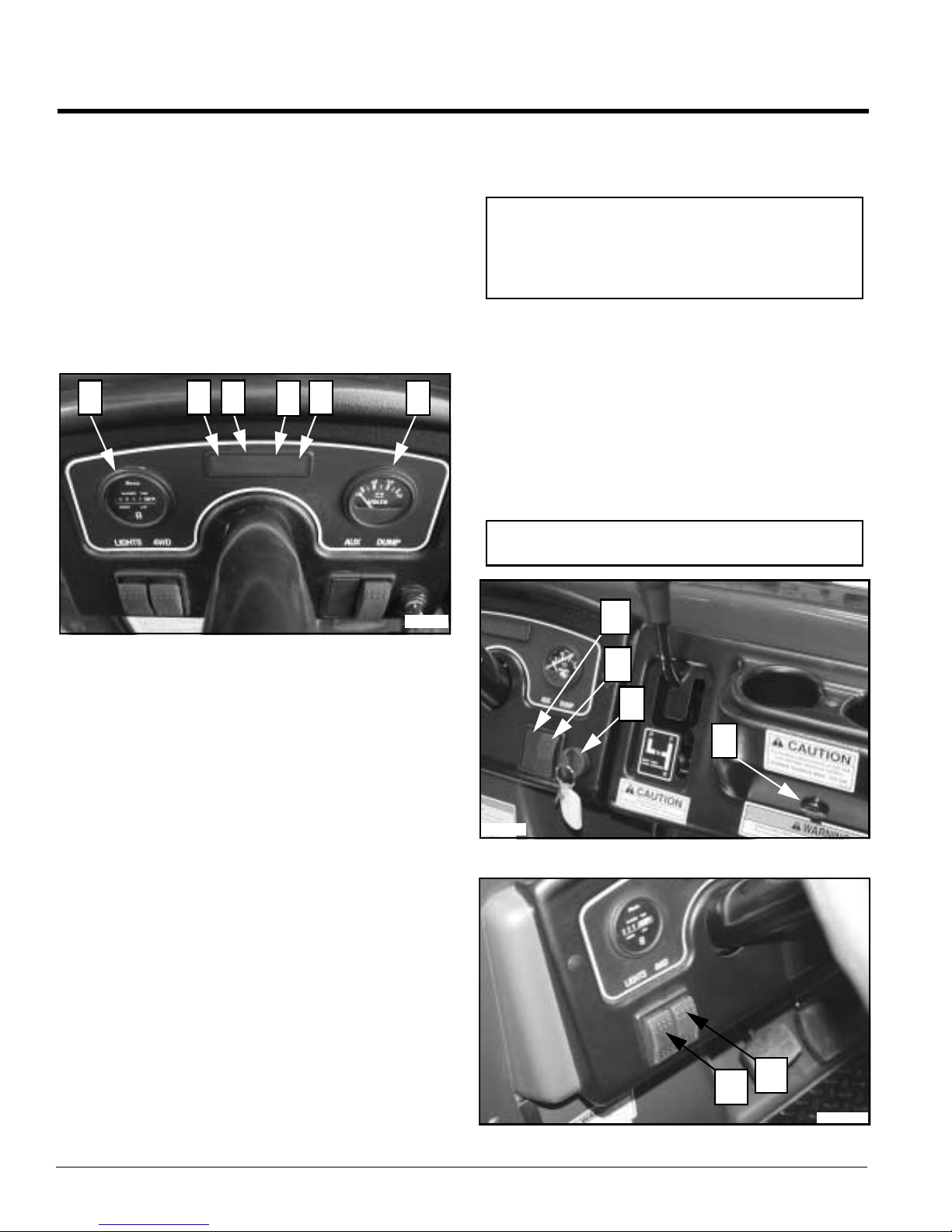
Indicating Lights and Gauges
Refer to Figure 4-1:
#1 Hour Meter: Indicates number of hours, to the
nearest 1/10 of an hour, the vehiclehas run.
#2 Park Brake Light:Indicates park brake is on when
illuminated. Do not move vehicle with park brake
light on. See note below.
#3 4-Wheel Drive Light: Indicates 4-wheel drive is
activated when illuminated.
#4 Neutral Light: Indicates shift selector is in neutral
when illuminated.
1 2
3
54
6
lower cargo box. Release switch at any position to
stop cargo box.Release switchimmediately if
Power Bed Lift Cylinder makes a ratchet noise.
IMPORTANT: The Power Bed Lift is protected by an
internal clutch in both directions and will make a loud
“ratchet” noise indicating end of travel has been
reached or Pow er Bed Lift is overloaded. Release
switch immediately when this noise is heard.
#10 Auxiliary SwitchSlot:12volton/off accessory with
switch may be installed at this location.
#11 Light Switch: Turns on head and tail lights. Press
topof switchto turn onlights and bottomof switchto
turn offlights.
#12 4-Wheel Drive Switch: Engages the4-wheel drive
system.Press topof switchtoengage 4-wheeldrive
and bottom of switch to disengage 4-wheel drive.
The 4-wheel drive system should be used only
when required to get through a difficult situation.
NOTE: 4x4 drive should not be engaged at transport
speed or on hard surface roads.
24696
Figure 4-1
#5 Oil Light: Indicates low oil pressure when
illuminated. Stop engine immediately. Checkoil
levelandadd if low. See yourauthorized Land Pride
dealerif oil light stayson and engine isfull of oil. It is
normal for the oil light to come on whenever the
ignition switch is turned on and will stay onuntil
engine is running.
#6 Volt Meter: Indicates battery is charging. Check
battery if volt meter registers a charge thatis lower
thannormal. Seeyour authorizedLandPride dealer
if battery is good and volt meter still registers low
charge.
Switches
Refer to Figure 4-2 and Figure 4-3:
#7 PowerPlugOutlet: Locatedon the dashis a power
plug outlet forconnecting 12 volt accessories such
as a cell phone or light.
#8 Ignition Switch: Starts and stops engine. Vertical
position is off.Turn switch key clockwise to start
engine. See “GeneralOperation” on page 15 for
correct vehicle starting procedures.
#9 Dump Switch: An electric cylinder raises and
lowersthecargobox.Press topofswitchand holdto
raise cargo box. Press bottom of switch andhold to
24693
10
9
8
Figure 4-2
Figure 4-3
7
12
11
21460
4220ST & 4420ST Light Utility Vehicles 700-504M
16
8/05/08

Section 4: Operating Instructions
Table of Contents
Choke
Refer to Figure 4-4:
#13 Choke Control: Located under the driver’s seat.
Use to choke engine whenstarting. Pull onknob to
start a cold engine. Release knob after engine has
started. Do not choke an engine that is hotfrom
operating, engine flooding may result.
13
22386
Figure 4-4
Floor Pedals
Refer to Figure 4-5:
#14 Brake Pedal: Applying pressure to brake pedal
instead of acceleratorpedal with your foot will slow
downand/or stopvehicle.Riding or resting your foot
on the pedal unnecessarily willwear the brakes out
prematurely.
#15 Accelerator Pedal: Changes engine rpm and
vehicle ground speed. Press down on the
accelerator pedal with your footto increase speed
and let upon the pedal to decreasespeed. Vehicle
should not move when engine is idling. Adjust
engineidle speedif vehiclemoveswhileaccelerator
pedal is not being depressed.
Shift Selector and Park Brake
Refer to Figure 4-6:
#16 Shift Selector & Park Brake Control: Sets and
releases the park brake and changes trans-axle
gears from neutral to forwardor reverse. Always
start engine in park or neutral.
• To place trans-axle in neutral from park position,
move shift selectorup and over to theleft and then
pull straight down to neutral position.
• From neutral, move shift selector over to the right
and up to place trans-axle in forward gear.
• From neutral, move shift selector over to the right
and down to place trans-axle in reverse gear.
• Make a full stop by letting up on accelerator pedal
and applying brakes before returning shift selector
to park or switching from reverse to forward and
forward to reverse.
16
22482
Shift Selector Shown in Park
Figure 4-6
Figure 4-5
8/05/08
14
15
24694
4220ST & 4420ST Light Utility Vehicles 700-504M
17

Table of Contents
Section 4: Operating Instructions
Fuel Gauge
Refer to Figure 4-7:
#17 Fuel Gauge: The fuel gauge, located on the gas
tank, displays approximately how much fuel you
have in the fuel tank. Always park vehicle on level
ground to get an accurate reading. The fuel tank is
empty when the fuel gauge needle points to E and
full when the needle points to F.
17
Release
Button
18
Tongue
19
Retractor
22485
Figure 4-8
22489
Figure 4-7
Seat Belts
!
WARNING
Seat belts should fit snugly and as low around the hips as
possible. Wearing seat belts high around the waist greatly
increases the chances of that person being injured in a
dangerous situation.
!
WARNING
Neveruse a seat belt for morethan one person and never buckle
the seat belt to a buckle designed to receive the other seat belt.
Twoseat belts are factor y supplied with the bench seat. A
third accessory seat belt may be added. See “Treker
Accessories” on page 24. It is the responsibility of the
operator and passenger to decide if their situation
warrants using seat belts. Make sure seats and seat
belts are properly fastened to the frame.
Seat Belt Components
Refer to Figure 4-8:
#18 Seat Belt: Theseat beltis thebelt thatextendsfrom
the retractor when pulled across your lap to be
buckled. It is located on the left side of the driver’s
seat and right side of the passenger’s seat.
#19 Buckle: Both operator and passenger buckles are
located in the middle. It secures the seat belt in
place.
Seat Belt Operation
Pull the seat belt across your hips and insert its tongue
into the buckle until you hear it snap. Release the seat
belt by pressing the release button in the center of the
buckle. Guide the seat belt to its original position as it
retracts to keep it aligned and to preventits tongue from
striking and damaging surfaces on the vehicle.
Cup Holders
Refer to Figure 4-9:
A removable rivet secures the cup holder to the dash.
The cups may be removed from the dash for cleaning.
Cup Holders
22479
Figure 4-9
4220ST & 4420ST Light Utility Vehicles 700-504M
18
8/05/08

Table of Contents
Section 4: Operating Instructions
Glove Box Enclosure
Refer to Figure 4-10:
Unlock glove box by inserting key and rotating clockwise
90 degrees to the position shown. Rotate twist lock
clockwise another 90 degrees to open. Toclose, push
glove box lid shut. To lock while shut, rotate key 90
degrees counterclockwise and remove. Key can be
removed in locked and unlocked positions.
Keyed Twist Lock
(Shown Unlocked)
23534
Figure 4-10
Cargo Box / Flat Bed Set-Up
!
CAUTION
Always load front of cargo box first and back last. Never load
back with more weight than the front.
!
DANGER
Make sure area behind cargo box is clear of personnel before
raising the cargo box. Bodily harm can result from being
pinched between cargo box and another object or from a load
dumping and/or rolling onto a bystander.
Thecargo box isfactory standardwith removabletailgate
and side panels for changing cargo box into a flatbed.
Refer to Figure 4-11:
1. Remove cotter pins (#6) and flat washers (#5) from
tailgate cable pins(#8). (2-places)
2. Remove 1/4”-20 hex screws (#4) and tailgate pivots
(#1) from tailgate. (2-places)
3. Pull gate release lever (#7) back on both sides and
remove gate (#3) from cargo box.
4. Replace flat washers (#5) and cotter pins(#6) in
tailgate cable pins(#8) forstorage.
234698
Figure 4-11
Refer to Figure 4-12:
5. Remove5 5/16”-18 hex flange screws (#10) and right
hand side panel (#9) as shown.
6. Repeat step 5 for left hand side panel.
234699
Figure 4-12
8/05/08
4220ST & 4420ST Light Utility Vehicles 700-504M
19

Section 4: Operating Instructions
Table of Contents
Towing
The Treker iscapable of being towed behind a tractor or
another vehicle as long as certain precautions are
followed:
• Theignition switch must be turned off.
• Thegear selector must be placed in neutral position.
• Thevehicle must be towed with a rigid tow-bar that is
designed to tow the gross weight of the Treker. See
"Section 10: Specifications and Capacities"on page 45
for vehicle gross weight.
• Tow-barmust be securely attached to the Treker at a
location that willnot damage the vehicle orcome loose
from the vehicle.
• Owner/usertakes on all responsibility and liability
resulting from attaching tow-bar to the Treker and to the
vehicle towing the Treker.
• Donot allow anyoneto ride inthe Treker whileit is being
towed.
• Donot tow a trailer or vehicle behind the Treker thatis
being towed.
• Donot towvehicle atspeeds over 25 mph. Thevehicle
is designed to travel up to 25 mph. Higher speeds may
resultindamage tothe Treker, vehicletowing theTreker
and personnel.
• Slowdown when turning to prevent loss of control and
rollovers.
• Obeyall state and local laws for towing vehicles.
Engine Performance
All small gas enginesneed fuel,air, and spar k inexactly
the r ight proportions in order to run properly at peak
performance.Bad orstale fuel, afouled spark plug,a wet
or corroded spark plug wire, agummed up carburetor,a
wet or dirty air filter, a low oil situation, incomplete fuel
combustion,carburetoricing, highoil situation(gas inthe
oil reservoir), and low engine temperature are all causes
of small gas engine problems or diminished
performance.
Fuel Quality
The normal shelf life of gasoline from the time it leaves
the refinery is about 30 days. Unused gas that is stored
too long can oxidize and break down causing formation
of gum and varnish deposits in carburetors, needle
valves,jets and venturis. This stopsor chokes offflow of
proper fuel/air mixture.
Incomplete Combustion
Incomplete combustionis when fuel is not fully bur ned in
the engine combustion chamber. This condition can
occur when an engine is started but is not allowed to run
long enough to reach full operating temperature. Cold
weathercan accelerate this condition. Also, fouledspark
plugs,wet electrical circuits and/or a plugged air filterwill
prevent fuel from being fully burned.
Unburnedfuel pools on topof the piston and seeps down
the cylinder walls into the oil reservoir. Often the oil
dipstick will show an oil over-fill condition as fuel
accumulates in the reservoir.
The oil reservoir filling up with gas can foul the spark
plugs. If left unchecked, oil will become so diluted with
gasoline that it can no longerfunction as alubricant. Itis
extremely impor tant to change oil and oil filter often
wheneverthereis ahigh frequency of gas gettinginto the
oilreser voir.Notchanging oil and oil filteroften canresult
in premature wear on cylinder walls and piston rings.
Also, replace fouled spark plugs, regap weak plugs,
check electrical system for capability of delivering a
strong spar k and clean the air filter when dirty.
Cold Weather Operation
Small gasoline engines must get up to operating
temperature before they will operate properly. Most air
cooled engines draw a large volume of air through their
intakefan. In sub-zero temperatures or freezing weather
it can become almost impossible for an engine to reach
normal operating temperature unless intake air is
restricted or warmer air is fed into the carburetor. Land
Pride offers a cold weather kit that directs air warmed
from the exhaust manifold into the carburetor.
Chokes, throttle cables, and other mechanical linkages
are also subject to freezing and sticking in cold weather.
Products like WD-40 or dry graphite lubricants can be
invaluable in keeping these items working freely.
Whenever possible, park your Treker in a warm, dry
environment to allow time for the linkages to dry out.
Draining the tank or running the engine until the tank is
empty can result in dried out gasketsthat, whendry, will
crack and leak. Also, emptying metal fuel tanks and
storagecontainers can result in corroded containers and
contaminated fuel.
Land Pride highly recommends using a fuel stabilizer or
oxygen inhibitor such as STA-BIL.
4220ST & 4420ST Light Utility Vehicles 700-504M
20
8/05/08

Section 4: Operating Instructions
Table of Contents
Traveling Tips From the Trail Masters
At Land Pride wewant you to get maximumworking and
recreational enjoyment out of your utility vehicle. If your
work project or recreational adventure is going to take
you on anextended ride deep into thewilderness orway
out on the prairie, you’ll need to seriously consider some
of the following tips from experienced pros about safety,
gear, clothing, supplies and driving techniques.
Preparation and Planning
Do a complete equipment check as follows:
1. Make sure you have plenty offuel and oilto make the
trip and then some.
2. Make sure your tires have proper inflation, your lug
bolts are tight and that you have a spare and the tools
to change, repair and inflate a tire.Consider adding a
puncture sealant to your tires as a preventative
measure.
3. Check for any loose or missing parts and definitely
makethose needed repairs before going anywhere.It
is especially important that you check steering,
braking, throttle, electrical and engine components
thoroughly.
Plan Your Route
1. Plan your route, destination and rendezvous points
before starting out.
2. Don’t go it alone if at all possible. Taking someone
elsealongreduces thepotential forlossof lifeormajor
injury from inclement weather, animal attacks, or
accidents. Besides, it’s more fun when you have
someone to share the adventure with.
3. Obtain trail or area maps of your travel routes to and
from your destination. Communicate yourtravelplans
to responsible friends and or proper authorities. Plan
rendezvous points at conspicuous landmarks along
yourroutejust in case yourun into unexpectedtrouble
on the trail.
4. Make sure you take a weather radio and two-way
communication devices such as cell phones or long
range-two way radios. It is also good to have ground
flares, a flare gun, a smoke canister, emergency
strobe light, a reflecting mirror, matches fora signal
fire and a compass.
Plan Your Gear
1. Check the short and longrange weather forecast and
take protective gear and clothing to cover all
contingencies. It doesn’t have to snow for you to fall
victim to hypothermia or exposure. Take or wear
appropriate eyeand head protection,gloves,boots, a
long sleeve shirt, long pants, a jacket,rain gear, dry
socks and a full change of dry clothing.
2. Plan your gear and gear up for the best and worst of
environmental conditions.
3. Packa first aid kit, sunblocker, lip balm, insect
repellent, personal medications, water, tarp or tent,
flash light, survival knife, binoculars, camera, tool kit,
rope, duct tape,tow strap, winch or come-along,
eating utensils, cooking utensils and high energytrail
food.
4. Tie and lash down your gear and supplies securely.
Keepthe bulk of the weight centered and mounted as
low as possible on the vehicle in order to maintain a
lowcenter of gravity forsafe and stableoff-road travel.
Going Out on the Trail
1. When it’s time to hit the trail “take it all in” but do it
safely!
2. Make sure you brief yourpassenger onproper safety
procedures like keeping hands, arms, feet andother
bodily appendages inside the vehicle. Passengers
shouldonly be transported in factorysupplied seating.
3. Operator and passenger areresponsible for deciding
if their situation warrants using Seat Belts.
4. Avoidoperating on excessivelysteep hills and
especially on hills that are steeper than 15 degrees.
Avoidcrossing slopes if possible and don’t make
sharp uphill steering corrections or a rollover could
result. If your vehicle starts to tip overon a slope turn
the front wheels quickly down hill to regain stability
andcontrol. Thebest wayto climbmost hills is to drive
straight up while maintaining a steady groundspeed
and constant engine rpm. The best way to descend
mosthillsis straightdownwhile usingsteady pressure
on the brakes without locking them up. Locking up the
brakes in a steep downhill situation can result in loss
oftraction, steering and control. Whenyou mustcross
a slope on soft terrain, keepthe front wheels turned
slightly uphill and maintain a constant speed and a
straight line of travel.
5. Driving too fast, being inattentive and turning too
sharplyon slipperysurfacescan resultinrolloversand
accidents almost quicker than any other ground
condition. Snow cover, wet trails, loose graveland
frozen ground can all contribute to this dangerous
condition.In theseconditions maintain sharp focuson
the trail ahead. Don’t make sharp turns and avoid the
needforhard brakingif at all possible.Ifyoudo start to
slideturn the frontwheels inthe direction ofthe skidto
regain control.
6. Avoidpaved surfaces. Land Pride vehicles are
designed exclusively for off-road use only. We
understand that occasionally operatorshave to cross
publicroads or right of waysto gain access to workor
recreationsites,but don’tget inthe wayoffastertraffic
and cross quicklyand safely.
7. Land Pride Vehicles with shielded torque converters
are capable of making intermittent stream crossings
where the depth of water briefly comes into contact
with the bottom of floorboards, butyou mustkeep
these considerations in mind; you must know how
8/05/08
4220ST & 4420ST Light Utility Vehicles 700-504M
21

Table of Contents
Section 4: Operating Instructions
deep the water is and the strengthof the current.
Cross where youhave a gradual incline for entry and
exit and the bottom is fairly clean and free of
obstacles. Maintain a slow steady speed disturbing
the stream bed as little as possible. If you submerge
theengine orthe whole vehicle,do not attempt to start
the vehicle but takeit to your nearest Land Pride
dealer immediately.After intermittent stream or
shallowwater crossings, dry out the brake linings and
drivebelt byslightly accelerating the engine rpm while
riding the brakes momentarily until full drive power
and braking are restored. You may lose forward
momentum and powerif water gets into the sealed
torque converter and drive belt through the
enclosure’s vents. Always remove the CVT drain cap
to drain anywater that may have entered the
enclosure. Replace cap once all water is drained.
8. Backing up in an off-road situation might seem a
simplething todo toa novice,buthavingto backdown
a hill is a very dangerous situation.If you are on level
ground always look behind youand back up slowly. If
you find yourself having to back down a hill,apply the
brakes very lightly. Hard braking can cause total loss
of control anda rollover situation. Try to back straight
down the hill without turning. Turning in this situation
can also cause a rollover.
9. Wheneverpossible, park your vehicle on a level
surface,set the park brake by placing shiftselector in
(P) and remove ignition key. Ifyou do have to park on
a hillside makesure you chock the rear wheels on the
downhill side topreventa rollaway. It’s a good idea to
keep your spare key stashed separately.
10. Never operate a vehicle under the influence of drugs
or alcohol. When you’redriving off-road vehicles you
need to keepyour senses keen and capable of quick
reaction, sharp perception and good balance.
11. Working orrecreation inthe deepwildernessor onthe
prairies can be personally rewarding and very
enjoyable to those who truly love and understand
nature and the outdoors. Good judgement, maturity,
proper preparation and planning can turn these
adventuresinto great experiences you’ll talk about for
a lifetime. Share theseadventures with young people
wheneveryou can and show them how to do it
properly. Don’t let anyone under 16 operate this
vehicle. They just aren’t mature and experienced
enough to takeon the serious responsibility of
operating a vehicle in the off-road environment
without the benefit of an experienced adult with them.
Remember, the only one whocan prevent and avoid
an accident is the operator in control and that’s you!
4220ST & 4420ST Light Utility Vehicles 700-504M
22
8/05/08

Section 5: Options and Accessories
Section 5: Options and Accessories
Table of Contents
Treker Options
Front Bumper
Refer to Figure 5-1:
The front bumper is the most economical bumperoption.
It can be unbolted from the Treker to add the optional
brush guard.
Front Bumper
21145
Front Bumper
Figure 5-1
Heavy Duty Brush Guard
Refer to Figure 5-2:
The Heavy Duty Brush Guard withfront hitch receiver is
a great option for accessor ies and front protection. The
hitch receiver on the Heavy Duty Brush Guard is
removable for adding a winch and roller fairlead
accessory. The front cargo accessory rack (not shown)
can be mounted to the Brush Guard.
Tires
Refer to Figure 5-3:
There are two types of tires availablefor your Land Pride
Treker. See Figure 5-3. The AllTerrain Tire isa good tire
to choose when tractionis your firstprior ity.This tireis a
tough tire for going over rough terrain. It can be
purchased mounted on gray rims or black rims.
The Turf Tire,mounted on gray rims, is a good selection
when one wants to preserve the terrain being traveled
over. Golf courses, parks and other maintained areas
make the Turf Tire an excellent choice.
All Terrain Tire
Figure 5-3
Turf Tire
21143
Heavy Duty
Brush Guard
22484
Heavy Duty Brush Guard
Figure 5-2
8/05/08
Hitch Receiver
4220ST & 4420ST Light Utility Vehicles 700-504M
23

Section 5: Options and Accessories
Table of Contents
Treker Accessories
A variety of accessory equipment has been designed to
complement your needs and makeyour Land Pride
Treker a very functional and useful vehicle. See your
nearest Land Pride Dealer for all available accessories.
Accessories available are:
• 2,000lb. Winch
• RollerFairlead
• RearTire Chains
• FrontTire chains
• GrabLight
• VerticalGun Case
• FifthWheel Trailer
• FrontBumper
• FrontBrush Guard
• FrontRack
• Rearhitch
• BackScreen
• BackScreen Head Rest
• HeadRest
• MudFlaps
• 60”Snow Blade
• CanopyTop - Black
• FrontWindshieldas
• HardCab Enclosure with
Hard Doors
• FrontBoot Guards
• RearBoot Guards
• SkidPlate
• 3rdSeat Belt
• ElectricSpin Spreader
• Back-upLight
• Back-upAlarm
Electric Spin Spreader
Refer to Figure 5-1:
The Land Pride Electr ic Spin Spreader is a highly
versatile full component package designed to plant or
spread seeds. It can then be used to spread pr illed or
granulated fertilizer, lime, gypsum, and other soil
conditioning amendments at distances ranging from 4 ft.
to20 ft.The combination spinspreader/planter por tion of
this system can also be used inthe off-season to spread
sand or salt for winter icing or slick snow conditions.
The combination of maximum versatility and narrow to
widespread pattern makes the ElectricSpin Spreaderan
excellent choice for applications in wild game foodplots,
hunting clubs, hunting resorts, ranches, farms, game
preserves, landscaping, hobby farming, smaller
nurseries, and gardens.
4220ST & 4420ST Light Utility Vehicles 700-504M
24
23921
Figure 5-1
The Land Pride Electric Spin Spreader can be attached
to any vehicle equipped with a 2" receiver hitch and
12 volt accessory receptacle. Description and part
number are listed below. See your nearest Land Pride
dealer for additional information.
ELECTRIC SPIN SPREADER . . . . . . . 701-130A
8/05/08

Section 6: Maintenance
Section 6: Maintenance
Table of Contents
General Maintenance
!
WARNING
Read and observe all safety warnings in this manual and in the
engine service manual.
!
WARNING
Except when checking or changing components, always keep
protective shields on for safety as well as for cleanliness.
!
WARNING
Keep engine clean of oil, grease, trash and debris which can
cause engine overheating, fires and belt wear. Clean only after
engine has completely cooled. Wear gloves to protect hands
from cuts, puncture wounds and burns.
!
WARNING
DO NOT have engine running when servicing or making
adjustments to the vehicle. Shut engine off, place transmission
in park and remove ignition switch key for maximum safety.
Some repairs require theassistance of atrained service
mechanic and should not be attempted by unskilled
personnel. Consult your Land Pride dealer when
assistance is needed.
Securing Vehicle for Maintenance
Beforeservicingthe vehiclethefollowingproceduremust
be met to secure the vehicle:
1. Park vehicle on a level surface. Don’t workunder or
around a vehicle parked on an incline.
2. Set shift selector in Park.
3. Turn ignition switch off and remove switch key.
4. Chock front and back side of the wheels not being
raised off the ground when jacking a vehicleor when
ground surface slopes.
5. Always use jack stands to support the vehicle when
working under the vehicle.
6. Always secure cargo box in the up position when
working under the cargo box.
Torque Values
Wheel Lug Nuts
!
DANGER
Repairs or maintenance specifically requiring engine power
should be performed by trained personnel only. Transmission
gearshould be set in neutral with tiresproperlychockedor with
drive tires properly supported off the floor. Enclosed areas
should be properly ventilated to prevent carbon monoxide
poisoning.
!
DANGER
Exercise extreme caution when working with and around the
belt drive. Make certain the engine cannot be accidentally
started. Shut engine off and remove ignition switch key for
maximum safety. Repairs or maintenance requiring engine
power should be performed by trained personnel only.
Regular maintenance is the best prevention for costly
downtime or expensive, premature repair. The following
pages contain suggested maintenance information and
schedules which the operator should follow on a routine
basis.
Remain alert for unusualnoises; they could besignaling
a problem. Visually inspect vehicle for any abnormal
wear or damage. A good time to detect potential
problems is while performing scheduled maintenance
service. Correcting the problem asquickly as possible is
the best insurance.
!
WARNING
Particular attention must be given to tightening the wheel lug
nuts. Not torquing these items correctly may result in loss of a
wheel, which can cause personal injury and damage to the
vehicle.
Torque Values
FT -lbs. Nm
Wheel lug nuts 65 - 75 88.14 - 101.7
Alwayscheckwheellug nut torque valuestwo hoursafter
initial operation and twohours after each tirerepair and/or
replacement
100 hours of operation. See "Maintenance Schedule" on
page 36.
.Routinely check lug nut torque valves every
Engine Torques
For engine torque values, see engine owner’s manual.
All Other Torques
For all other torques refer to “Torque Values Chart”
page 51.
Tire Maintenance
Use only tires recommended by Land Pride.
Itis important foryour safetyand the safetyof others that
the tires have correct air pressure. Check air pressurein
8/05/08
4220ST & 4420ST Light Utility Vehicles 700-504M
25

Section 6: Maintenance
Table of Contents
all four tires before each use. Visually inspect tires for
loss of air throughout each day of operation. See Tire
Inflation Chart below for correct tire pressure.
Tire Inflation Chart
Tire Inflation PSI
Front Tires
Rear Tires
7 psi*
7 psi*
* Tire pressure may be increased to accommodate
additionalcargo load. Maximumtire pressure is notedon
tire side wall.
Jacking the Vehicle
!
DANGER
For your safety and safety of others, a jacked vehicle must be
supported properly with jack stands before working under and
around it. Also the wheels on the ground must be chocked on
both sides to prevent vehicle from rolling forward or backward.
.
21123
Figure 6-1
IMPORTANT: Use a hydraulic jack, floor jack, or
scissor type jack to lift vehicle. Do not use a handyman
jackor bumper jack and don’t jack against the bumper,
body, front 4-wheel drive transfercase, rear trans-axle,
or axles.
1. Secure vehicle for maintenance.See "Securing
Vehicle for Maintenance" on page 25.
2. Loosen the lug nuts on a wheel being removed
approximately1/2turncounterclockwisewhile it is still
on the ground.
3. See important note above. Place proper jack under
vehicle as follows:
a. Front tires: Refer to Figure 6-1. Place jack under
body frame where the A-Frame struts attach to
the body.
b. Rear tires: Refer to Figure 6-2. Center the jack
under the receiverhitch.
4. Jack vehicle only high enough to do the work
intended.
5. Support vehiclesecurely with jack stands before
working under or around the vehicle.
6. Work may now be performed on the vehicle. Be sure
to properly torque all bolts that were loosened. Wheel
bolts should be torqued after vehicle is lowered to the
ground.
7. Lower vehicle by first jacking vehicle up highenough
to remove jack stands. Then carefully lower jack until
vehicle is on the ground.
8. Remove wheel chocks.
21121
Figure 6-2
Shock Absorber Adjustment
Traveling fast or carrying heavy loads may cause shock
absorbers to bottom-out making the ride rough. The
mounting position of the rear shocks is adjustable to
increase or decrease firmness of ride.Typically,they are
set soft forslow speeds and light loads. Fast speeds and
heavy loads require a firmer setting.
Adjust rear shock absorber position as follows:
1. Refer to "Jacking the Vehicle" instructions to jack
vehicle up before repositioning the rear shocks.
2. RefertoFigure 6-3.Locate shockabsorber’stop three
mounting holes.
4220ST & 4420ST Light Utility Vehicles 700-504M
26
8/05/08
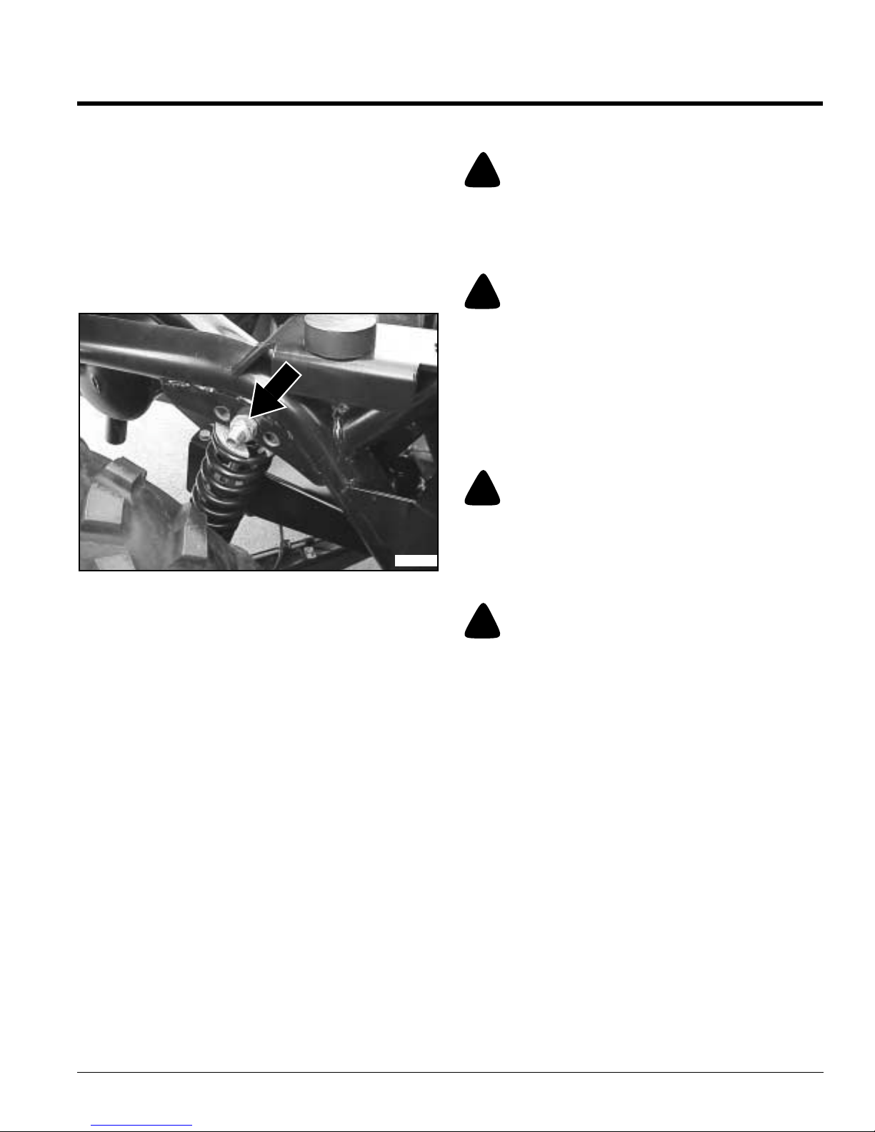
Section 6: Maintenance
Table of Contents
3. Removelocknutand hexboltsecuringshockabsorber
to the vehicleframe.
4. Reposition rear shocksbackwards or forwardsto
change load carrying capabilities as follows:
a. Repositioning the shockbackwards increases
ride firmness and load carrying capabilities.
b. Repositioning the shock forwards makes the ride
softer.
5. Lower vehicle as outlined in the instructions for
“Jacking the Vehicle” on page 26.
21124
Figure 6-3
Battery
!
WARNING
Acid can cause serious injury to skin and eyes. Avoid skin
contact with battery acid and always wear eye protection when
checking the battery. Flush area with clean water and call a
physician immediately. Acid will also damage clothing.
!
WARNING
Incorrect battery cable connections can damage vehicle’s
electrical system and cause battery cables to spark. Sparks
around a battery can result in a battery gas explosion and
personal injury.
• Always disconnect negative (black) battery cable before
disconnecting positive (red) cable.
• Always reconnect positive (red) battery cable to positive
(+) post before reconnecting negative (black) cable to
negative (-) post.
!
WARNING
Keep battery terminals from touching any metal parts when
removing or installing the battery. Do not allow metal tools to
short between battery terminals and metal vehicle parts. Sparks
can cause a battery gas explosion which will result in personal
injury.
Electrical System
The electrical system is protected by fuses located in the
fuse box. The fuse box lid, located on the vehicle’s left
side panel behind the driver’s seat, is attached with
Velcro. Remove lid by pulling out at the top two corners.
On the lid is a diagram illustrating fuses and their
locations.Fusesmay be purchased through yournearest
Land Pr ide Dealer.
Common circuit problems are shorts, corroded or dirty
terminals, loose connections, defectivewire insulation or
broken wires. Switches, solenoids and ignition
components can also not function, causing a short or
open circuit.
Before attempting any fault diagnosis of the electrical
system, use a test light or voltmeterto check battery
voltage. If battery voltage is satisfactory, check
cleanliness and tightness of terminals and ground
connections. A general understanding of electrical
servicing and use of basic test equipment is necessary
for troubleshooting and repair.
Major overhaul or repair of starting motor and alternator
should be performed by trained technicians only.
!
WARNING
Do not allow an open flame near the battery when charging.
Hydrogen gas forms inside the battery. This gas is both toxic
and flammable and may cause an explosion if exposed to a
flame.
The battery is located under the seat. It may be either a
maintenance-free sealed battery or a maintenance-free
battery with removable vent caps. Inspect your battery
and know which battery you have. Water cannot be
added to sealed batteries as the vent caps are not
removable.
Land Pr ide recommends a maintenance-free batter y
size BCI group U1/U1R. The batter y should also have a
minimum of 300 cold cranking AMPs and 375 cranking
AMPs at 32oF. The battery support is designed tohold a
larger automotive style battery. Simply reposition the
J-hooks to the higher holes when installing a larger
battery. Always follow manufacturer’s maintenance,
safety, stor ing and charging specifications.
8/05/08
4220ST & 4420ST Light Utility Vehicles 700-504M
27

Section 6: Maintenance
Table of Contents
Adding Water to the Battery
!
CAUTION
Do not overfill battery with water. Electrolytes may overflow
and damage paint, wiring or structure. Use soap and water to
clean the battery. Be careful not to get soap and water into the
battery. Use baking soda mixed in water to clean corrosion off
the terminals.
There should be no need to add water throughout the
normal life of a maintenance-free battery. However,
abnormal electrical system conditions or high ambient
temperatures may boil off more water than normal.
Batteries with removable vent caps should have the
water level checked in them once a year. Water level in
each cell should be up to the level indicator. If not, add
water.Distilled watershould beused tofill eachcell inthe
battery. However, tap water may be used if tap water is
not hard or does not have high mineral or alkali content.
Do not overfill. Have the charging system checked by
your local LandPride dealerif the battery requires water
every few months.
Charging the Battery
Batteries that are severely discharged may not take or
indicatea charge immediately.Some automaticchargers
need a minimum voltage before they will start charging
and some will not indicate a charging condition at the
meter until the batter y reaches a minimum charge.
Consult your charger manual to determine how your
charger works.
When recharging batteries, please followthese
important safety precautions:
1. Secure vehicle for maintenance.See "Securing
Vehicle for Maintenance" on page 25.
2. Read manufacturer’s instructions for the charger.
3. Leave battery charger unplugged until its cables are
connected to the battery.
4. Choosethe correctbatterycharger toproperly charge
a battery.
5. Put on protectiveeye wear, rubber gloves, work
clothes and remove all jewelry.
6. Don’t charge a frozen battery. Allow battery to warm
up to about 60 deg. F before charging.
7. Charge batteries in a well ventilated area.
8. Neversmoke while charging a battery.
9. If applicable, remove vent caps and check battery’s
waterlevel.Ifwater level is low,followinstructions for
"Adding Water to the Battery" above.
10. Ifapplicable, reinstall vent caps before charging.
11. Setcharger to 12 volts.
12. Plugin and turn on charger.
13. Don’twiggle connections to check contact while
charger is turned on or plugged in.
14. Chooselowest amperage setting initially. Once
charger is on and battery is charging you may want to
choose a higher amp setting to reduce charging time.
Jump Starting the Battery
The batter y will discharge if lights or any otherelectr ical
equipment is left on after engine has stopped running.
Also, the battery will discharge if lights or power plug
outletis used over a prolong period whileengine is idling.
The engine can be jump-started with a booster battery.
Follow procedures listed below when jump-starting.
Prepare Vehicle to Jump-Start
1. Use only a 12-volt battery to jump-start the Treker.
Higher voltages can damage starter motor and other
electrical components. Do not use a 24 volt battery or
two 12-volt batteries connected in series.
2. Do not disconnect a vehicle’s battery that needs a
jump-start. Disconnectingthebatterycan damage the
vehicle’s electrical system.
3. Park second vehicle close to the vehicleneeding a
boost without touching the two vehicles together. Set
parking brake on both vehicles.
4. Turn off all ignition switches, electric switches, light
switches and set parking brakes on both vehicles.
Connecting Jumper Cables
Refer to Figure 6-4 on page 29:
1. Inspect battery terminals for corrosion. Remove
excess corrosion before connecting jumper cables.
2. Connect one end of the red jumper cable to the
positive (+) terminal on the dead battery.
3. Connect the other end of the red jumper cable to the
positive (+) terminal on the booster battery.
4. Connect one end of the black jumper cable to the
negative (-) terminal on the booster battery.
!
WARNING
Make connection in step 5 below to a metal surface away from
battery.Never connect to negative (-) post of dead battery or to
a metal surface near the battery. Sparking near thebattery can
result in a battery gas explosion and personal injury.
5. Connect the other end of the black jumper cable to a
metalsurfaceon the vehiclethat has the deadbattery.
6. Inspect jumper cables to makecertain they are not in
thewayof movingor rotating components.Reposition
any cables that will be in the way.
4220ST & 4420ST Light Utility Vehicles 700-504M
28
8/05/08

Table of Contents
Section 6: Maintenance
!
DANGER
Make certain everyone is clear of all moving and rotating
components before starting either vehicle.
Refer to Figure 6-4:
7. Start thelivevehicleand runit ata moderatespeed for
a few minutes to charge the dead battery.
8. After waiting a few minutes, start the dead vehicle. It
should start within several tries. If vehicle does not
start, then theproblem might be something other than
the battery.
Red Jumper Cable
12 volt
Booster
Battery
Metal Surface
Black Jumper Cable
Figure 6-4
Dead
Battery
Disconnecting Jumper Cables
Refer to Figure 6-4:
1. Let both vehiclesrun for severalminutes to charge up
the dead battery before removing jumper cables.
2. Disconnectblack jumper cable from themetal surface
on the vehiclethat had the dead battery.
3. Disconnect the other end of the black jumper cable
from the negativepost on the booster battery.
4. Disconnect the red jumpercable from the positive(+)
post on the booster battery.
5. Disconnectthe other end of the red jumpercable from
the positive (+) post on the dead battery.
6. Drive the vehicle that had the dead battery for a while
to recharge battery or recharge battery with a battery
charger. Follow all battery charger instructions when
recharging a battery with a battery charger.
Fuel System
!
DANGER
• Observe safe fuel handling precautions.
• Do not smoke while handling fuel.
• Do not fill tank with engine running or while engine is hot.
Allow engine to cool before filling. Spilling fuel over
engine, muffler, or a hot object may result in a fire or
explosion.
• Allow engine to cool before servicing the fuel system.
• Clean up any gasoline spills immediately.
• Keepfuel away from open flame or spark.
• Storevehicle away from open flame or spark if there is fuel
in the tank.
• Use extra caution when handling gasoline and other fuels.
They are flammable and vaporsare explosive. A fire or
explosion from gasoline can burn you and others and can
damage property.
• Refuel outdoors preferably, or in well ventilated areas.
• Neverattempt to start engine when there is a strong odor of
gasoline fumes present. Locate and correct cause.
• Storegasoline in an approved container and keep it out of
children’s reach.
• Never buy more than a 30 day supply of gasoline.
• Do not fill gasoline containersinside a vehicle, on a truck,
or on a trailer. Interior carpets and plastic truck bed liners
insulate container and slow loss of static charge.
• Whenpractical, removeequipmentfromtruck or trailerand
refuelequipmentwith its wheels on the ground. If this is not
possible,then refuel equipment on the truckor trailer using
a portable container and not a gasoline dispenser nozzle. If
a gasoline dispenser nozzle must be used, keep nozzle in
contact with rim of fuel tank or container opening at all
times until fueling is complete.
• Gasoline is harmful or fatal if swallowed.
• Long-termexposureto vapors can causeserious injury and
illness.
• Avoid prolonged breathing of vapors.
• Keepface away from nozzle and gas tank opening.
• Keepgas away from eyes and skin.
The fuel tank is located behind the passengers seat.
Total fuel capacity is 8 gallons.
When filling the fuel tank, set park brake, turn off engine
and removeignition key. Clean dir t from aroundfuel tank
cap, remove cap and begin filling. When finished, screw
cap back on securely and wipe up any spilled gasoline.
Use regular unleaded gasoline with an octane rating of
87 or higher.
IMPORTANT: Never use methanol, gasoline
containing methanol and/or gasohol containing more
than 10% ethanol. These fuels can damage the
vehicle’s fuel system. Do not mix oil with gasoline.
Using a fuel stabilizer/conditioner in the vehicle can
provide benefits such as:
1. Keeps gasoline fresh during storage of 90 days or
less. Empty fuel tank for longer storage.
2. Cleans engine during operation.
3. Eliminates gum-like varnish build-up in the fuel system.
8/05/08
4220ST & 4420ST Light Utility Vehicles 700-504M
29

Section 6: Maintenance
Table of Contents
IMPORTANT: Do not use fuel additives containing
methanol or ethanol.
Add correct amount of gas stabilizer/conditioner to the
gas. For best results, always follow manufacturer’s
directions when adding gas stabilizer/conditioner.
Fuel Filter Maintenance
Refer to Figure 6-5:
Thefuel filter (Land Pride Part No.831-031C) is installed
in the fuel line between the fuel tank and engine. Check
it every 100 hours for excessive water accumulation or
sediment and replace if necessary. Otherwise replace
afterevery 300 hours of operation or annually, whichever
occurs first. Also check fuel tank and fuel line for cracks
and leaks every 100 hours.
Emptying the Fuel Tank
!
DANGER
Never siphon a fuel tank by sucking on a hose with your mouth.
Fuel vapors and gas are harmful to your lungs and can
permanently damage them. Always use a siphon pump.
The fuel tank will need emptying when preparing for long
term storage or replacing a damaged one.
1. Secure vehicle for maintenance.See "Securing
Vehicle for Maintenance" on page 25.
2. Follow all Fuel Safety Cautions, Warnings and
Dangers.
3. Remove gas cap and siphon fuel through fill opening
with a siphon pump into an approved gas container.
Make sure container or containers are capable of
holding all the gas. Do not dump fuel on the ground.
Engine Maintenance
General Information
Prevent engine fires. Clean engine compartment daily.
Cleancooling fan screen of all debris including dirt, trash
and oil. Make sure engine surface and cooling fins are
clean. Check engine compartment often for cleanliness
when traveling over areas that produce high amounts of
airborne combustible materials.
24701
Figure 6-5
1. Secure vehicle for maintenance.See "Securing
Vehicle for Maintenance" on page 25.
2. Following all Fuel Safety Cautions and Warnings,
remove clamps securing fuel filter andremove fuel
filter for inspection.
3. Checkfuel filter for sediment andwater accumulation.
Check fuel lines for cracks and leaks.
4. Replace damaged fuel lines with new ones.
5. Replace fuel filter when sediment or excessive water
is present.
6. Reattach fuel filter to fuel line with arrow on filter
pointing in the same direction fuel flows in the line.
Fuel flows towards the engine.
7. Install hose clamps around fuel filter.
8. Start vehicleand inspect for fuel leaks along fuel line
and fuel filter.
9. Shut off vehicle. Removeblocks securing cargo box
up and lowercargo box.
10. Remove wheel chocks if used.
Detailed instructions and recommendations for break-in
and regular maintenance are specified in the engine
operator’s manual. Engine warranty is backed by the
engine manufacturer. Please refer to engine
manufacturer’s manual for engine servicing, lubricating
oil levels, oil quality and viscosity recommendations, bolt
torques, etc. Special attention should be paid to
applicable data that is not duplicated here.
High Altitude Carburetor Kit
IMPORTANT: The air-fuel mixture in carburetors
modified for high elevation is too lean when
operating at elevations below 5,000 feet. Operating
engines with modified carburetors below 5,000 feet
can result in engine overheating and serious engine
damage. Return carburetor to original factory
specifications when operating at low elevations.
Trekervehicles shippedfrom the factory are stocked with
carburetors designed to operate efficiently between 0
and 4,999 feet. Carburetor change over kits for different
altitudes may be purchased from your nearest Land
Pride Dealer as follows:
Elevation Carburetor Kit No.
0’-4999’ 99201-ZG8-1050
5,000’-7,999’ 99201-ZG8-1020
8,000’ & up 99201-ZG8-1000
4220ST & 4420ST Light Utility Vehicles 700-504M
30
8/05/08

Section 6: Maintenance
Table of Contents
Drive Belt Replacement
Replace dr ive belt when it shows signs of severe cuts,
tears, excessive weather checking, cracking and/or
burns caused by slipping. Slight raveling of belt covering
does not require belt replacement. Trim raveling with a
sharp knife.
Inspect belt pulley grooves and flanges for wear. A new
belt, or one in good condition, should never run against
bottom of pulley groove except when engine is idling.
Replace pulley when this is the case, otherwise belt will
lose power and slip excessively.
Never pry a belt to get it on a pulley as this will cut or
damage the belt fibers.
Keep oil and grease away from belts and never use belt
dressings. Any of these willdestroy the belt composition
in a very short time.
!
CAUTION
Securely support cargo box in the up position to prevent
injury when working under the cargo box.
!
CAUTION
Make certain to keep fingers from getting caught between belt
and pulley when rotating belt over pulley.
This should open driven pulley side walls allowing
room to remove the belt.
4. Removebelt by rolling it off over the driven pulley and
then lifting it up off the drive pulley.
5. Reinstall new belt by placing it overthe drive pulley
and then rolling it over the variabledriven pulley.
6. Reinstall belt cover and fasteners.
7. Reconnect battery negative cable.
8. Remove blocks securing cargo box up and lower
cargo box.
Driven Pulley Maintenance
Refer to Figure 6-6:
The dr iven pulley should be inspected for wearat the
cam shoes to prevent damage to pulley and pulley
compression spr ing.
Refer to Figure 6-7:
1. Secure vehicle for maintenance.See "Securing
Vehicle for Maintenance" on page 25.
2. Remove screws securing drive belt cover. Pull cover
back to inspect.
3. Checkcam shoes on driven pulleyevery 100 hours or
less for wear. Cam shoes should be at least 1/16”
above aluminum hub when measuring parallel to the
cam incline.
Refer to Figure 6-6:
1. Secure vehicle for maintenance.See "Securing
Vehicle for Maintenance" on page 25.
Driven Pulley
Drive Pulley
21126
Figure 6-6
Drive Belt Replacement
Part No. Part Description
816-546C Belt, CVT
2. Remove hardware securing drive belt cover and
remove cover.
3. Hand squeeze the belt together between drivepulley
and driven pulleyto forcebelt into the driven pulley.
!
DANGER
Donot replace cam shoes without contacting yournearestLand
Pride vehicle dealer for help. The compression spring can
cause bodily injury if replacement is done incorrectly.
4. Replace all cam shoes if there is less than 1/16”
clearancebetween aluminum housings.Make certain
youcontact your nearestLand Pride vehicledealer for
help when replacing them.
Aluminum
Housing
Replace cam shoes if there is
less than 1/16” clearance
between aluminum housings.
Figure 6-7
Cam Shoes
3-Required
24703
Cam Shoe Replacement
Part No. Part Description
6030-3001 DRIVEN PULLEY CAM SHOE
(3 required)
8/05/08
4220ST & 4420ST Light Utility Vehicles 700-504M
31

Table of Contents
Section 6: Maintenance
Engine Air Filter Maintenance
Refer to Figure 6-8 & Figure 6-9:
NOTE:Do notoperate engine witha damaged airfilter
or without an air filter element. Dirt will enter engine
causing dust ingested engine problems.
NOTE: Do not block air intake to air cleaner. Placing
an object on the platform in front of the air intake
snorkel or allowingloose clothing to drape overthe
snorkel could block the snorkel opening.
1. Replace filter element with Land Pride filter element
No. 839-323C every 300 hours or every year,
(whichevercomes first). Service more frequently
when used in dusty conditions.
2. Releaseretainingclips(#5) toremovecanisteraccess
cover(#4) and filterelement (#3).Clean canister (#2)
with a damp cloth.
3. Before installing new filter element, inspect it by
placing a bright light inside and rotate element slowly,
looking for any holes and tears in the paper. Also
check gaskets for cuts or tears. Donot attempt to use
a damaged element. A damaged element will allow
abrasive particles to enter the engine.
4. Install new filterelement (#3) with open end first.
5. Reinstall canister access cover (#4). Make sure it
seals all around canister body (#2) before tighten
retaining clips (#5).
6. Check rubber burp cap (#6). Clean if plugged.
7. Checkallfittings and clampsperiodically fortightness.
Inspect hoses forholes or cracks.
8. Periodicallycheckengine intake hose (#1) forsigns of
ingested dust. Locate and repair source of ingested
dirt.
9. Neveroperate vehiclewithout a filter element (#3).
Insert Open End First
Air Intake
Snorkel
Air Cleaner
Canister
Retaining Clip
Access Cover
Location - Under Hinged Seat
Figure 6-9
24704
Engine Air Filter Handling
Refer to Figure 6-8 and Figure 6-9:
A specially designed dr y filter is standard equipment on
the Treker and supplies clean combustion air to the
engine.
Prevent costly and non-warrantable premature engine
damage by maintaining the vehicle air filter properly.
Many engine problems are due to improper handling of
the air filter. Dust and dirt that gets pass the air filter will
damage engine cylinder, piston and bearings in a few
hours.
Prevent costly and non-warrantable premature engine
problemsby avoiding thefollowing common mishandling:
• Overservicing
• Improperinstallation
• Damagedair filtering system
• Incorrectair filter element
Over Servicing
Over servicing occurs when an air filter element is
inspectedand/or replaced too often. Dustand dirt canfall
off the filter element onto the canister where it can be
sucked into the intake system. Only a few grams of dirt
getting into an engine during each filter inspection can
prematurely produce dust ingested engine problems.
A partially dirty air filter element is not harmful to the
engine.
Figure 6-8
4220ST & 4420ST Light Utility Vehicles 700-504M
32
24705
The air filter element should be changed before it
becomes too dirty and restricts air flow to the engine
hindering its performance. Replace air filter element
immediately should this happen. Engines thatdo not get
proper amounts of air will draw in excessive amounts of
gas causing premature engine problems.
8/05/08

Section 6: Maintenance
Table of Contents
The frequency of needing to change the air filter is
largely determined by driving conditions. Dusty
conditions will require more frequent servicing.
A dirty filter element should always be replaced with a
newelement.Improper cleaningprocedures can getdust
on the inside of the filter causing dirt ingestion and
engine problems. The air filter warranty expires upon
cleaning or servicing a used filter in any manner.
Land Pride does not warranty a dust ing ested engine
problem if aused air filter element hasbeen cleaned
or serviced in any manner.
Improper Installation
Improper installation occurs when dust leaks past the
seals. The filter element must be aligned within the
canister and proper ly seated on both ends to preventdirt
from enter ing the engine.
Damaged Air Filtering System
A damaged air filtering system often occurs from
mishandling the filter element and driving the vehicle in
areas that could damage the canister.
Bangingand/or bumpingthe filter element againsta solid
object such as a tire or blowing the element with air can
damage the seals and/or force dust and dirt particles
through the filter media creating a hole for dirt to pass
through to the engine.
CVT Snorkel Filter Maintenance
Refer to Figure 6-10:
Located under the seat on the passenger side are the
engine air intakesnorkel and CVT air intake snorkel.
Inside the CVT snorkel is a filter element that should be
inspected at every oil change.
1. Check filter element (#2) by removing itfrom CVT air
intake snorkel (#1) and inspecting itfor dirt and
damage.
2. Ifdirty, wash filterelement inwarmsoapywater.Rinse
and let dry before reinstalling.
3. Replace with a new filter element if torn or cut.
4. Checkallfittings and clampsperiodically fortightness.
Inspect hose forholes or cracks.
CVT Cover
Engine
Air Filter
Driving the vehicle carelessly over rough terrain, jutting
sticks,heavy brush and severe rocks can damage the air
cleaner canister. Periodically inspect the air cleaner
canister for external damage and replace if necessar y.
Incorrect Air Filter Element
The air filter must remain intact to block passage of dirt
and foreign particles. It must be of sufficient size and
construction to withstand stresses, caused by rapid
cycling of air volume demanded by the engine, without
cracking or tearing under fatigue and pressure. Its filter
elements must havethe correct media composition, filter
area,micron size and dimensions to properly filter the air
of dirt whileat the sametime passingsufficient air tothe
engine.
Land Pride and the enginemanufacturers have carefully
selected a reliable filter designed to fit the needs of the
Treker engines. Always specify a Land Pride filter part
number 839-323C.
Always use genuine Land Pride filters. Not using
original equipment replacement par ts is an
alteration and will not be considered for warranty in
the event of a dust ingested engine problem.
Engine Air
Intake Snorkel
CVT Air
Intake Snorkel
24710
Figure 6-10
8/05/08
4220ST & 4420ST Light Utility Vehicles 700-504M
33

Table of Contents
Section 6: Maintenance
Exhaust System
Preventexhaust fires.Clean exhaustsystem daily while
cold of all dirt and trash. Checkexhaust system often for
cleanliness especially while traveling over areas that
produce high amounts of airborne combustible
materials. Check spark arrester to make sure it is clean
and in good working condition.
Spark Arrester
Refer to Figure 6-11:
!
DANGER
The spark arrester does not stop all fire emitting sparks from
escapingthe muffler.Use extremecaution when driving through
dry grass, brush and other firehazard materials. Never stop or
park vehicle over combustible materials.
Muffle
Spark Arrester
Screen
!
WARNING
The muffler is very hot and will burn upon contact. Allow time
to cool before servicing the spark arrester.
!
CAUTION
To maintain efficiency,the spark arrestermust be serviced every
100 hours.
!
CAUTION
Be careful not to damage spark arrester screen when cleaning.
The spar k arrester is mounted on the end of the muffler
tail pipe and is designed to suppress sparks from
escaping the muffler while they are still glowing.
Spark Arrester Maintenance Schedule
• Inspectevery 100 hours for carbon build-up and screen
damage.
• Cleanwhenever carbon build-upis visibleor whenever
lost of engine power is detected.
• Replacewhen damaged.
Spark Arrester Maintenance Procedure
1. Remove spark arrester mounting screw (#1) and
removespark arrester (#2) from muffler exhaust pipe.
2. Remove carbon deposits from both sides of spark
arrester screen with a wire bristle brush. Be careful
not to damage spark arrester screen.
3. Inspect spark arrester for holes or breaks in the
screen and replace if damaged.
4. Reattach spark arrester to muffler with mounting
screw.
24706
Spark Arrester
Figure 6-11
4220ST & 4420ST Light Utility Vehicles 700-504M
34
8/05/08

Section 6: Maintenance
Table of Contents
Park Brake Adjustment
The Park Brake Assembly is factory shimmed to the
correct gap and should not require adjusting. Make
adjustments only if park brake pads do not hold when
shift selector is in park or if brake pads drag on the disc
when out of par k. Have your nearestLand Pr ide Service
Center replace brake pads and/or shims if the following
adjustments are not satisfactory.
Refer to Figure 6-13:
The park brake caliper is located onthe right side of the
rear trans-axle case.
IMPORTANT: If the park brake lever is not properly
adjusted, the brake pads can drag resulting in
excessive brake wear and decreased engine power.
When adjusted properly, the park brake lever (#4) will
be located in its ball detent position when shift selector
is in neutral.
IMPORTANT: Make certain the wheels arechocked
and the cargo box is securely supported in the up
position before working on the Park Brake calipers.
1. Park vehicle on a level surface. Don’t workunder or
around a vehicle parked on an incline.
2. Set shift selector in park.
3. Chock front and back of rear wheels.
4. Secure cargo boxin the up position.
5. Change shift selector to neutral.
6. Turn ignition switch off and remove switch key.
7. Remove cotter pin (#1) and linchpin (#2).
8. Loosen jam nut (#3).
9. Allow park brakelever (#4) to seat itself in the ball
detents.
10. Adjustyoke (#7) in or out until yoke linchpin hole
aligns with brakelever (#4) linchpin hole.
11. Reinsert linchpin (#2).
12. Insert cotter pin (#1) and securein place by bending
one leg out.
13. Tightenjam nut (#3) against yoke (#7).
14. Check park brake’sability to hold and release by:
a. Placing shift selector in park and checkto make
sure brake pads (#5) are seated tight against
rotary disc (#6).The vehicle should not movewith
shift selector in this position.
b. Return shift selector to neutral andcheck to make
sure park brakepads (#5) do not make contact
with rotary disc (#6).
c. If park brake still does not work properly, have
your nearest LandPride service center inspect
the brakes before continuingto use the vehicle.
15. Setshiftselector in park, lower cargo boxand remove
wheel chocks.
1
2
5
6
Ball Detents
4
7
3
23546
Park Brake Calipers
Figure 6-13
8/05/08
4220ST & 4420ST Light Utility Vehicles 700-504M
35

Section 6: Maintenance
Table of Contents
Maintenance Schedule
Maintenance Operation Daily
Check Engine Oil level (9) X37
Check Tire Pressure X25
Clean Engine and exhaust (11) X 30 & 34
Inspect All Nuts and Bolts for Tightness X25
Check and Clean Area Around Engine Air Intake X32
Check Fuel Line Hoses, Clamps, & Tank for Leaks XX30
Clean Spark Arrester (1) X34
Check Wheel Lug Nuts (Torque 65 to 75 Ft. lbs.) (2) X25
Check Master Cylinder Brake Fluid Level X41
Check Battery Charge and Water Level X27
Check In-line Fuel Filter (10) XX30
Check CVT Snorkel Filter (3) & (4) XX33
Change Engine Oil (3), (4) & (9) XX37
Change Engine Oil Filter (3), (4) & (9) XX38
Check & Regap Spark Plugs (.028 to .031 in.) (9) XX
Check Rear Trans-axle Case Fluid Level (7) XX39
Check Center Transfer Case Fluid Level (7) XX40
Check Front Differential Case Fluid Level (7) XX40
Check Driven Pulley Wear Buttons X31
Inspect Drum Brakes (6) X
Inspect Parking Brake (6) X
Replace Air Cleaner Filter Element (5) XX32
Replace Spark Plugs (9) XX
Check and Adjust engine idle Speed (6) & (9) XX
Check Valve Clearance (6) & (9) XX
Replace In-line Fuel Filter XX30
Clean Combustion Chamber (8) & (9) XX
Clean Battery and Terminals X27
Check Drive Belt and Pulleys X31
Every
100 Hrs.
Every
300 Hrs.
Every
500 Hrs.
Every
6 Mos.
Every
Year
Refer to
Page
Reference Notes for above Maintenance Operation:
(1) Clean spark arrester whenever loss of engine power is noticed or every 100 hours (whichever comes first).
(2) Check tightness after first 2 hours of initial operation and after removal for repair and replacement.
(3) Make first engine oil and filter change after the first month of operation or at 20 hours of operation (whichever comes first).
(4) Service every 100 hours or 6 months (whichever comes first).
(5) Replace air cleaner filter element if damaged, every 300 hours or ever season (whichevercomes first). Replace more frequently when used in
dusty conditions.
(6) Have a Land Pride dealer perform this service every year or every 300 hours (whichever comes first).
(7) Change every year or every 400 hours (whichever comes first). Change immediately if contaminated with water.
(8) Have a Land Pride dealer perform this service every year or every 500 hours (whichever comes first).
(9) See also your Honda Engine Owner’s Manual.
(10) Replace fuel filter immediately if excessive water accumulation or sediment is found.
(11) Maker certainengine and exhaust are cool beforecleaning. Check and clean engine fan cooling screen often when travelingin dirty trashyterrain.
4220ST & 4420ST Light Utility Vehicles 700-504M
36
8/05/08
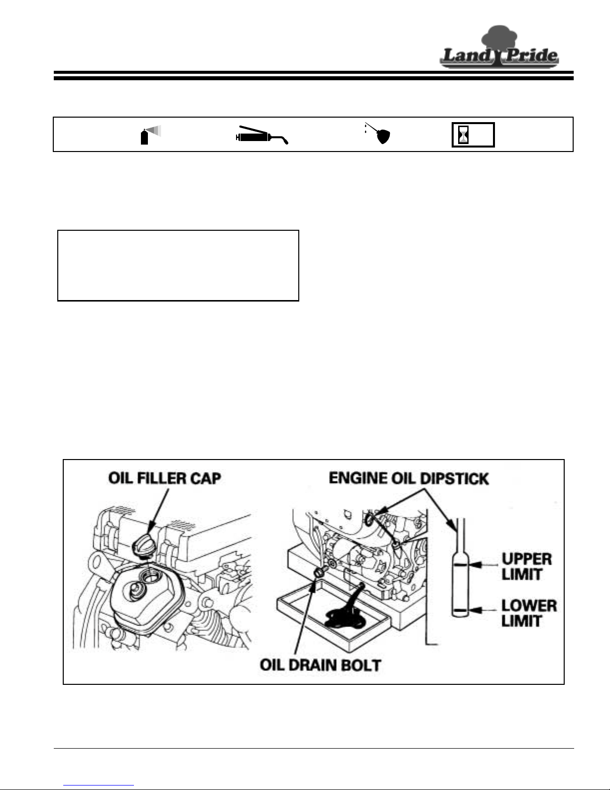
Section 7: Lubrication
Section 7: Lubrication
Table of Contents
Lubrication
Legend
Multi-purpose
spray lube
Multi-purpose
grease lube
Engine Oil
A general description for engine oil maintenance,
recommendations and capacities is provided below.See
Engine Operator’s Manual for a detailed descr iption.
IMPORTANT:
Runningengine lowon oil cancause engine damage
and void engine warranty.
Overfilling engine of oil can causeloss of power,
engine damage and void engine warranty.
Maintenance Schedule
• Checkoil level after each use.
• Makefirstoil change after the first month of operation or
at 20 hours of operation (whichever comes first).
• Makeall subsequent oil changes every 6 months or
every 100 hours of operation (whichever comes first).
Multi-purpose
oil lube
50
Intervals in hours
at which lubrication
is required
Level Check
Refer to Figure 7-1:
Checkengine oil dailywith dipstick located at the engine
left front side as follows:
1. Parkvehicleon a levelsurface,setpark brake,turnoff
ignition switch and removeswitch key.
2. Allow enough time for engine oil to settle before
checking oil level with dipstick.
3. Remove dipstick and wipe clean.
4. Fullyinsert dipstickandremove.Checkoillevelshown
on dipstick.
5. If oil level on dipstick is low, remove filler cap located
top of rear valve cover and fill with recommended oil.
Repeat steps 2, 3 and 4 until oil level on dipstick
indicates full. Do not overfill or plug fouling and
power loss will occur.
6. Replace filler cap and dipstick.
8/05/08
21135
Engine Oil Fill, Drain and Check Locations
Figure 7-1
4220ST & 4420ST Light Utility Vehicles 700-504M
37

Table of Contents
Section 7: Lubrication
Oil And Filter Change
6 mo/100 hrs
Refer to Figure 7-1 on page 37:
See also "Section10: Specifications and Capacities" on
page 45.
Filler cap location: Top of rear valve cover
Dipstick location: Front left side of engine
Drain plug location: Front bottom center of engine
Type of Lubrication: SAE 10W30
Engine Oil Capacity: 1.5 US qts. with filter replacement,
1.1 US qts. without filter replacement.
Quantity: Fill oil to upper limit mark on dipstick.
Refer to Figure 7-2 and Figure 7-3:
Warm oil drains quickly and completely.Therefore, drain
used engine oil while engine is still warm as follows:
1. Parkvehicleon a levelsurface,setpark brake,turnoff
ignition switch and removeswitch key.
2. Placea suitablecontainer below engineto catch used
oil. Remove filter access coverand drain plug to allow
oil to drain out.
3. Removeoil filter with a filter wrench andlet remaining
oil drain out. Discard oil filter.
4. Clean engine filter base.
5. Coat new filter O-ring withclean engine oiland install
filter to engine filter base.
6. Hand tighten oil filter until O-ring seats. Finish
tightening by turning the filter to the specified turning
angle or torque with a torque wrench.
Turning Angle: 7/8 of a turn
Torque: 22 N.m (2.2 kgf.m, 16 lb-ft)
7. Reinstall and tighten drain plug securely.
8. Dispose of used motor oil and filter in a manner that is
compatible with theenvironment. Do not throw used
oil in the trash, pour it on the ground, or down a drain.
9. Fill engine with 1.5 US quarts of 10W30 oil. Do not
overfill. See "Level Check" on page 37.
10. Replacefiller cap, start engine and check oil filter for
leaks.
11. Stopengine andcheck oillevel as outlinedin section
titled “Engine Oil Level Check” on page 37.
21134
Oil Filter Location
Figure 7-2
21134
Oil Filter O-Ring
Figure 7-3
4220ST & 4420ST Light Utility Vehicles 700-504M
38
8/05/08

Table of Contents
Section 7: Lubrication
Case Oil
Ageneraldescription of maintenance, recommendations
and capacities for the trans-axle case, center transfer
case and front differential case are provided below.
Maintenance Schedule
• Check case housing for damage and possible oil
leakage after each use.
• Check oil level every 6 months or every 100 hours
(whichever comes first).
• Change oil once a year or every 400 hours (whichever
comes first).
Level Check
Oil must be drainedand refilledwith properquantities to
insurecorrect oillevelin thefront differentialcase. Check
rear trans-axle case and center transfercase oil at the fill
plug with a clean rod.The rodshould belong enough so
that it will not fall pass the fill opening.
1. Parkvehicleon a levelsurface,setpark brake,turnoff
ignition switch and removeswitch key.
2. Removefill cap and measure from top of fillhole to oil
levelin case. This should be approximately 4 1/2” for
rear trans-axle case,2” forcenter transfercase and
1/4” from bottom of fill opening for front differential
case.
3. Add correct lubrication if needed.(Don’t overfill)
4. Replace fill cap and tighten securely.
Oil Change
Warm oil drains quickly and completely. Drainused oil
while it is still warm as follows:
1. Parkvehicleon a levelsurface,setpark brake,turnoff
ignition switch and removeswitch key.
2. Place a suitablecontainer below housing to catch
used oil. Remove fill cap and drain plug.
3. Allow used oil to drain completely and then reinstall
drain plug and tighten securely.
4. Disposeof usedoil ina mannerthat iscompatible with
the environment. Donot throw used oil in the trash,
pour it on the ground, or down a drain.
5. Fill gear cases per capacities in "Section 10:
Specifications and Capacities" on page 45.
6. Replace fill cap and tighten securely.
Rear Trans-axle Case
6 mo/100 hrs
Refer to Figure 7-4 & Figure 7-5:
See also "Section10: Specifications and Capacities" on
page 45.
NOTE:Running trans-axle or driveline gearboxes low
on oil candamage seals,bearings and gears voiding
warranty for the trans-axleand gearboxes.
Fill cap location: Top center rear side (See Figure 7-4)
Drain plug location: At bottom left side (see Figure 7-5)
Type of lubrication: Mobil 424
Trans-axle case oil capacity: 20 oz.
Quantity: Fill to center line of output shaft.
(Approximately 4 1/2” from top offill opening to top
of oil level.)
Check and Fill Plug
24707a
Rear Trans-axle Check and Fill Plug
Figure 7-4
Drain Plug
24707b
8/05/08
Rear Trans-axle Drain Plug
Figure 7-5
4220ST & 4420ST Light Utility Vehicles 700-504M
39

Table of Contents
Section 7: Lubrication
Center Transfer Case
(4-Wheel Units Only)
6 mo/100 hrs
Refer to Figure 7-6:
See also "Section10: Specifications and Capacities" on
page 45.
Fill cap location: Top center (See arrow)
Drain plug location: Bottom Hex socket screw
Type of lubrication: 80/90 Gear Lube
Center transfer case oil capacity: 6 oz.
Quantity: Fill to center line of output shaft.
(Approximately2” from topof fill openingto top of oil
level.)
Check and
Fill Plug
24738
Center Transfer Case
Figure 7-6
Front Differential Case
(4-Wheel Units Only)
6 mo/100 hrs
Refer to Figure 7-7:
See also "Section10: Specifications and Capacities" on
page 45.
IMPORTANT: Differential may not function properly
and/or become damaged if wrong oil is installed.
Fill plug location: Left front side (See large arrow)
Drain plug location: Bottom center (see large arrow)
Type of lubrication: Mobil 424
Front differential Case oil capacity: 5 oz.
(Approximately 1/4” from bottom of fill opening to top of fill
opening.)
Check and Fill Plug
Oil should be 1/4” below to level with plug opening.
Oil may be added here by
removing breather hose.
Make sure check plug is
open when adding oil.
Always reinstall breather
hose when finished.
Drain Plug
21130
Front Differential Case
Figure 7-7
4220ST & 4420ST Light Utility Vehicles 700-504M
40
8/05/08
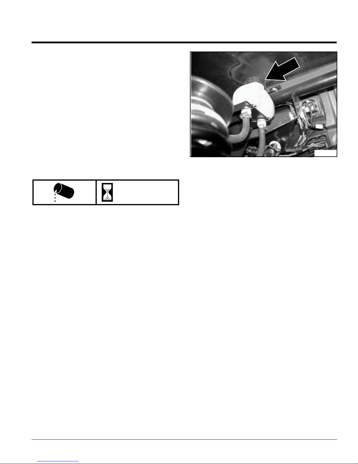
Table of Contents
Section 7: Lubrication
Brake Fluid
Brake Fluid Maintenance Schedule
• Checkfluid reservoir monthly.
• Fillreservoir immediately if low or if brakes begin to
fade.
Brake Fluid Visual Check and Fill
Refer to Figure 7-8:
The master cylinder fluid reservoir is attached to the
body frame under the front hood on the dr iver’s side.
Visually inspect fill line on the reservoir by turning the
steering wheel to the left and looking under the driver’s
side wheel well. Remove capand add DOT 3 fluid to the
reservoir through the wheel well with a squeeze bottle
and tube inserted into the reservoir.
Brake Fluid Type and Fill Location
21132
Master Cylinder Reservoir
Figure 7-8
100 hrs
See also "Section10: Specifications and Capacities" on
page 45
Fill cap location: Located on driver’s side of vehicle under
front hood. (see Figure 7-8)
Type of fluid:
Quantity: Fill to line on reservoir.
DOT 3
8/05/08
4220ST & 4420ST Light Utility Vehicles 700-504M
41

Table of Contents
Section 8: Seasonal Storage
Section 8: Seasonal Storage
Engine Preparation for Storage
!
CAUTION
Fuelvapors areflammable and explosive.Donot store a vehicle
withfuel in the tank in a building where fumes can reacha spark
or an open flames (i.e. plug-in sockets, light switches, light
fixtures, power tools, welders, pilot lights and stoves).
Engine exhaust fumes contain carbon monoxide. Do not run a
vehicle inside a building any longer than what it takesto move
it. Serious illness or death may result from prolong exposure to
carbon monoxide.
1. Take vehicle out of gear, set park brake and run
engine outside for15 minutes minimum. Then shut
vehicle off and removeignition key.
2. Drain oil from crankcase while engine is still warm.
3. Change oil filter. Referto page 38.
4. Refill with fresh oil of proper viscosity. Referto
page 37.
5. Replace fuel filter if needed. Referto page 30.
6. Prepare fuel system as follows:
Short term storage (90 days or less):
a. Siphon most of the fuel from the tank.
b. Add fuel stabilizer to tank per manufacturers
recommendation.
IMPORTANT: Do not use fuel additives containing
methanol or ethanol.
c. Fill fuel tank with fresh fuel to prevent water
condensation build-up.
d. Run engine to circulate fresh fuel throughout
engine components.
Long term storage (over 90 days):
a. Siphon most of the fuel from the tank.
b. Run engine until it stops from lack of fuel.
NOTE: Gasoline evaporates if leftin carburetor for
longperiods,forming gum and varnish deposits in the
carburetor. These deposits willcause engine flooding
and loss of power.
c. Remove spark plugs and pour a tablespoon of
engine oil into each spark plug hole. Install plugs,
but do not reconnect plug leads.
d. Crank engine with starter at least a dozen
revolutionsto distributeoil over cylinder walls and
valve mechanism.
7. Cleanexterior surface of engine. Spread a light film of
oiloverany exposedmetal surfacesof engine that are
subject to corrosion.
8. Clean dirt and chaff from cylinders and fins, blower
housing and muffler.
9. Check oil fill cap and fuel tank cap to make certain
they are securely in place.
Vehicle Storage Preparation
1. Perform separate engine preparations listed
previously before storing vehicle.
2. Store vehicle in a clean, dry place.
3. Alwaysplaceshiftselector inparkand remove ignition
key before dismounting from vehicle.
4. Always allow vehicleto cool before working on or
around it.
5. Remove all dirt and trash.
6. Clean and touch up all scrapes per “Section 9: Body
Repair” on page 43.
7. Checkthoroughly for any worn or damaged parts that
need replacing includingdecals and order them from
your Land Pride Dealer.
8. Thoroughly lubricate vehicle according to lubrication
instructions. See Section 7: Lubrication, page 37.
9. Block vehicle up to take weight off the tires.
NOTE: Do not deflate tires.
10. Cleanbattery and battery post. Checkbattery
electrolyte level. Protect battery from freezing
temperatures.Occasionally recharging batteryduring
storage will extend battery life.
11. Securea waterproof cover over the vehicle if stored
outside.
Vehicle Removal From Storage Preparation
1. Remove waterproof cover if used.
2. Clean vehicle, removing trashand dirt accumulation.
3. Install all safety shields and reviewsafetyprecautions
listed in this manual.
4. Reconnect spark plug leads to spark plugs.
5. Check engine oillevel.
6. Check trans-axle oil level. If 4-wheel drive, check 4wheel transfer case and front differential oillevel.
7. Charge battery.
8. Fill fuel tank with fresh gasoline.
9. Run vehicle at half speed for 5 minutes, checking
operation of steering control levers.
10. Stopengine and check for oil leaks, loosefittings and
overall condition of vehicle.
11. Tightenany bolts that may have loosened.
12. Check and inflate tires to correct air pressure.
4220ST & 4420ST Light Utility Vehicles 700-504M
42
8/05/08

Section 9: Body Repair
Section 9: Body Repair
Table of Contents
Introduction
Land Pr ide Treker bodies are constructed of ABS with
WeatherPro GtmColor Cap. Scuffs, light scratches and
deep gouges are in most situations repairable. Land
Pride recommends that you use a professional body
shop to restore your vehicle’s body. For your
consideration, we have provided below a list of
recommended tools, materials and steps suggested for
repairing the WeatherPro GtmColor Cap body.
NOTE: Land Pride does not supply required tools,
paint and materials needed to repair the vehicle body.
All tools, paint and materials should be purchased
locally.
Light Scuff
Required Tools and Materials (See note above)
• 1,000rpm buffing tool, DeWalt #849
• Meguiarsbuffing compound #8432
• Meguiarspolish #8232 (optional)
• Meguiarsmaroon cutting pad #W-7006
• Meguiarstan polishing pad #W-9006 (optional)
• Meguiarsbacking plate #W-64
• Softclean cotton cloths
Steps to Repair
1. Clean entire area of repair. Clean water is fine for this
purpose. Do not usesolvent as this willdamage the
body surface.
2. Install cutting pad #7006 on buffer (maroon pad).
3. Spread compound on area of repair, use about as
much as it takes to cover a half-dollar coin, this is a
good starting point.
4. Set buffing tool to lowest possible speed on dial, do
not buff at a high speed as this will heat and warp
material.
5. Buff damage area until surface scuff disappears. A
second and third application of compound may be
required. Keep buffer moving over surface, this will
help keep surface cool. Clean compound residue off
surface after each buffing operation. Do not continue
to buff compound until dry, or buff surface when dry.
Whenall scuff marks havebeen buffedoutthe surface
may still appear a little dull, if so, proceed to #6.
6. Install polish on surface as in step #3.
7. Spread #8232 polish on surface as in step #3.
8. Polish to a high lusteror as required to match
surrounding material.
9. Wipe clean with soft clean cloth; any dirt on cloth will
mar surface.
Scratch
Required Tools and Materials (See note to left)
• 1,000rpm buffing tool, DeWalt #849
• Meguiarsbuffing compound #8432
• Meguiarspolish #8232 (optional)
• Meguiarsmaroon cutting pad #W-7006
• Meguiarstan polishing pad #W-9006 (optional)
• Meguiarsbacking plate #W-64
• Softclean cotton cloths
• 3Minterface sanding pad #05774
• AirVantage finishing sander with 6-inch hook and loop
pad
• 3M-P800sanding film #00970
Steps to Repair
1. Clean entire area of repair. Clean water is fine for this
purpose. Do not usesolvent as this willdamage the
body surface.
2. Install interface-sanding pad onto finishing sander.
Attach sanding film to Interface pad. (Take care in
centering sanding pad and filmon sander.)
3. Sand surface using about 45 P.S.I.air pressure at tool
inlet,do not sand at a high pad speed,because speed
causes the sanding film to load with dust and heats
the body surface. Proper sander pad speed is based
on cut, travel speed, and downward pressureapplied
by the operator. To clean sanding pad surface,run
sander face at 90 degrees on the edge of a piece of
cardboard. This cleaning operation will help keep
sanding film clean and run cooler. Continue to sand
surface until original scratch damage is no longer
visible. Wipe surface with a cloth and then inspect to
be sure the entire original scratch has been fully
sanded away (very important).
4. Install cutting pad #7006 on buffer (maroon pad).
5. Spreadcompound #8432 on area of repair, use about
as much as it takes to covera half-dollar coin, this is a
good starting point.
6. Set buffing tool to lowest possible speed on dial, do
not buff at a high speed as this will heat and warp
material.
7. Buff sanded area until surface scuff disappears.
8. A second and third application of compound may be
required. Keep buffer moving over surface to help
keep surface cool. Clean compound residue off
surface after each buffing operation. Do not continue
to buff compound until dry.
9. Buff surface of body when dry. When all scuff marks
have been buffedout the surface may still appear a
little dull, if so, proceed to #10.
8/05/08
4220ST & 4420ST Light Utility Vehicles 700-504M
43

Section 9: Body Repair
Table of Contents
10. Installpolishing pad #W-9006 on buffer (tan pad).
11. Spread#8232 polish on surface asin step #3.
12. Polish to a high luster or as required to match
surrounding material.
13. Wipeclean with soft clean cloth; any dirt on cloth will
mar surface.
Deep Gouge
Required Tools and Materials (See note on page 43)
• 1,000rpm buffing tool, DeWalt #849
• EvercoatBody Filler Easy Sand
• SandingPad
• DuPontFull-Thane Primer 421-15
• DuPont3939 Cleaner
• DuPontSealer 42470
• DuPontChroma Base/ Clear Coat Paint System
• HVLPPaint Sprayer
Steps to Repair
1. Sand damaged area with 500-grit paper to remove
raisededges andto create abraded surfaceforproper
adhesion.
2. Fill damaged area with Evercoat body filler (2-part
system) and allow to completely dry.
3. Sanddown high spots with 500-grit paper. If recesses
are still visibledue to filler shrinkage, apply second
skimcoatand againallowtodrycompletely, thensand
surface flush with surrounding area.
4. Apply DuPont Full-Thane Primer 421-15 over body
filler.
5. Once primer is completely dry, clean surfacewith
DuPont 3939 Cleaner and againallow surfaceto dry
completely.
6. Apply 42470 Sealer over body filler.
7. Apply color-matched paint system with HVLP paint
sprayeraccording to supplier’s recommendations to
meet WeatherPro G’ssurface finish, i.e.DuPont’stwo
part Base/ Clear coat system.
4220ST & 4420ST Light Utility Vehicles 700-504M
44
8/05/08

Table of Contents
Section 10: Specifications and Capacities
Section 10: Specifications and Capacities
4220ST & 4420 ST Series
Engine Specifications
Engine Model Honda GX620K1 Lubrication Pressurized
Engine Type 4 stroke - air cooled Engine Oil Type SAE 10W30
Horse Power 20 Engine Oil Capacity 1.5 US qts. with filter change
Displacement 614 cc Engine Idle rpm 1250 rpm min. to 1350 rpm max.
Max. Torque 32.5 lb@2500 Max. Engine Static rpm 3800 rpm to 4000 rpm max.
Cylinders 2 Cooling Air
Valving OHV ACG Output 12V/20A
Fuel And Oil Specifications
Fuel Capacity 8 gallons Rear Trans-axle Case Capacity: 20 oz. Type: US Mobil 424
Fuel Type Unleaded fuel with 87 min. octane
(Methanol fuel not allowed)
Brake Fluid DOT 3 Front Differential Case Capacity: 5 oz. Type: US Mobil 424
Center Transfer Case Capacity: 6 oz. Type:
Vehicle Specifications
Headlights Two with standard 37.5 watt bulbs #894 4-Post Acc.Bar Standard
Tail Lights Two with standard bulbs #1157 Max. Speed 25 mph
Battery Type 12 volt, Size BCI, Group U1/U1R with
min. 300 CCA and 375 CCA at 32oF.
Back-up Light/Alarm Available as accessories Base Unit Total Payload* 1300 lbs.
Belt Drive Enclosed CVT
(Constantly Variable Transmission)
Ignition Keyed (Starts only in park and neutral.) Rear Cargo Box Capacity 900 lbs.
Gear Selection Park/Neutral/Forward/Reverse Maximum Tongue Weight 100 lbs.
Rear Park Brake Operator Gear selector automatically sets rear
brakes when placed in park.
Brake Type Front: Hydraulic disc
Rear: Hydraulic drum
Steering Type Rack & Pinion Wheel Base 76”
Steering Wheel Dia. 15" Tread Center Front 46.5"
Exhaust Protection Spark arrestor Tread Center Rear 47.5"
Frame Construction Tube & channel Width at front tires 54"
Frame. Suspension Independent A-ar ms, MacPherson struts Width at rear tires 58”
Rear Suspension Independent trailing arms
Coil/over adjustable shocks
Floorboards Steel safety plate Length 120”
Body Cowling ABS Composite in optional colors:
Green, Red, Yellow or Camouflage
Front Guard Optional bumper or brush guard Min. Ground Clearance 9 1/2”
Rear Hitch 2” receiver Tire Pressure Front & Rear = 7 psi**
Front Hitch 2” receiver available with
front brush guard option
Fenders Front: Integral with body
Rear: Mounted to cargobox Tire Type & Size (Rear) All-Terrain tread with
Seating Bench seat with two seat belts. Center
3rd seat belt available as an accessory.
Approximate Curb Weight 4220ST: 925 lbs.
Gross Vehicle Weight 4220ST: 2225 lbs.
Max. Towing Capacity 1200 lbs.
Carrying Capacity of Front
Optional Cargo Rack
Height With All-Terrain tires: 71"
Floorboard Height All-Terrain tires: 14"
Tire Type & Size (Front) All-Terrain tread with
* Base unit does not include optional cargo racks.
1.1 US qts. without filter change
US 80/90 gear lube
4420ST: 1234 lbs.
4420ST: 2534 lbs.
160 lbs.
With Turf tires: 70”
Turf tires: 13”
black or gray r ims: 25 x 8-12 (option)
Turf tread: 23 x 8.5-12 (option)
black or gray r ims: 25 x 11-12 (option)
Turf tread: 23x10.5-12 (option)
** Tire pressure may be increased to accommodate additional cargo load. Max.tire pressure is noted on tire side wall.
8/05/08
4220ST & 4420ST Light Utility Vehicles 700-504M
45

Section 11: Features and Benefits
Section 11: Features and Benefits
Features Benefits
20hp Honda OHV V-Twin Engine
25 MPH Top Speed
4-Wheeled Independent Suspension
Rack & Pinion
Automotive Type Steering
4- Post Accessory Bar
9 1/2" Minimum Ground Clearance
1,300 lb. Total Payload
4-Wheeled Automotive Style Braking
Constantly Variable Transmission
Large Open Operators Platform
8 Gallon Fuel Tank
58” Overall Width at Rear Tires
Cargo Box with Power Lift
Full Bench Seat
Wide Range Of Accessories
Enclosed CVT
Auto-Lock Differential
Overrunning Clutch
Seat Belts
Heavy Duty Brush Guard
Front Receiver
(With Heavy Duty Brush Guard Option)
High Mounted Air Intake
Dash Mounted Cup Holders
Locking Deep Well Glove Box
Dash Mounted Shifter
with Integral Park Brake
Removable Cargo Box Sides
Warranty
Table of Contents
4220ST & 4420 ST Series
For Proven Power & Dependability.
Able to go from job site to job site at a reasonable speed.
For Soft Ride & Excellent Stability.
For Easy Handling & Quick Response.
Offers Accessory Mounting Capabilities & Added Protection from Limbs &
Branches.
For Traversing Rough Terrain.
For Maximum Cargo and Gear Hauling Capabilities.
For Maximum Stopping Power & Control.
For Rapid Response & Easy Shifting.
For Maximum Operator & Passenger Comfort.
For Extended Operating Range.
For Maximum Stability.
For added convenience and maximum productivity.
More Spacious Seating.
To Meet Individual Customer Needs.
For enhanced stream crossing capability.
For maximum traction capability.
For environmental friendly traction and easy handling.
For extra measure of safety.
For added body protection.
For added versatility.
For enhanced stream crossing capability.
For added convenience.
For added security and convenience.
For added convenience.
For added versatility.
One year against manufacturing defects.
Two years manufactured engine warranty.
4220ST & 4420ST Light Utility Vehicles 700-504M
46
8/05/08

Table of Contents
Section 12: Troubleshooting
Section 12: T roubleshooting
Symptoms Probable Causes Suggested Remedies
Battery is dead
Battery will not charge up
Brakes are sticking (won’t release)
Brakes don’t function
Electrical System does not work
Key switch is not in the off position. Switch key to off position.
Battery is worn out or defective. Replace battery.
Starter solenoid is shorted. Replace starter solenoid.
Battery connections are loose or
corroded.
Battery fluid level is low. Add distilled water to battery cell.
Battery cell is dead. Replace battery as soon as possible.
Battery is worn out or defective.
Master cylinder linkage is out of
adjustment.
Master cylinder return spring is broken. Replace master cylinder return spring.
Ground debris in brake linkage. Clean debris from brake linkage.
Master cylinder oil level is low. Add brake fluid to the master cylinder.
Brake line is broken. Replace brake line.
Brake line has air in it. Bleed brake line and add brake fluid.
Master cylinder is defective. Replace master cylinder.
Electrical fuse is blown or missing. Replace electrical fuse.
Battery connections are loose or
corroded.
Disconnect and recharge battery.
Clean and tighten battery connections.
Adjust master cylinder linkage.
Clean and tighten battery connections.
Engine backfires
Engine knocks
Engine overheats
Battery is worn out or defective. Replace battery.
Ignition switch is defective. Replace ignition switch.
Spark plug is fouled. Replace or clean spark plug.
Fuel solenoid is stuck. See Honda Engine Manual.
Air intake restrictor upstream of air
cleaner is missing or incorrectly
installed.
Throttle cable is defective or out of
adjustment.
Engine speed is set too low. Adjust engine idle screw.
Fuel is stale or dirty. Replace fuel with new fuel.
Engine cooling fins are plugged. Allow engine to cool. Clean cooling
Engine oil level is low. Add specified engine oil.
Carburetor air intake tube is plugged. Clean air intake tube.
Air cleaning element is plugged or
missing.
Replace or correctly install air intake
restrictor.
Clean and oil throttle cable. Replace
worn or damaged cable.
fins with high pressure air.
Replace or clean air cleaner with air.
8/05/08
4220ST & 4420ST Light Utility Vehicles 700-504M
47

Table of Contents
Section 12: Troubleshooting
Symptoms Probable Causes Suggested Remedies
Engine loses power
Engine runs unevenly
Throttle cable is sticking. Clean and oil throttle cable. Replace
Choke cable is sticking. Clean and oil choke cable. Replace
Spark plugs are defective. Replace spark plugs.
Spark plugs are fouled. Clean spark plugs or replace.
Fuel supply is restricted. Check for dirt in fuel tank.
Fuel line is plugged, pinched, or kinked. Clean or replace fuel line.
Fuel leaks into the crankcase. Clean or replace fouled spark plugs.
Engine oil level is high. Drain excess oil, check for gas in the
Fuel octane is incorrect. Use unleaded 87 minimum octane.
Throttle cable is faulty or out of
adjustment.
Air cleaning element is plugged. Replace or clean air cleaner with air.
Engine is overheating. See Symptoms for engine
Electrical connections are loose. Reattach electrical connections.
Engine cooling fins are plugged. Allow engine to cool. Clean cooling
worn or damaged cable.
worn or damaged cable.
Verify choke position is not stuck on.
oil. Change if gas is present.
Adjust or replace throttle cable.
overheating.
fins with high pressure air.
Engine starts in gear
Throttle cable is sticking. Clean and oil throttle cable. Replace
worn or damaged cable.
Choke cable is sticking. Clean and oil choke cable. Replace
worn or damaged cable.
Fuel is stale or dirty. Replace fuel with new fuel.
Fuel line is plugged. Clean fuel line.
Fuel type is incorrect. Use unleaded 87 minimum octane.
(Methanol not allowed).
Fuel leaks into the crankcase. Clean or replace fouled spark plugs.
Verify choke position is not stuck on.
Spark Plug wiring is defective. Replace spark plug wiring.
Spark plug is defective. Replace spark plugs.
Spark plug is fouled. Clean spark plugs or replace.
Carburetor is not adjusted correctly. Adjust carburetor.
Air cleaner is plugged. Replace air cleaner.
Neutral switch is adjusted incorrectly. Adjust neutral switch to be engaged
with shift selector in neutral.
Shifter link is out of adjustment. With shift selector in neutral, adjust
shifter link at engine to be in neutral
position.
4220ST & 4420ST Light Utility Vehicles 700-504M
48
8/05/08

Table of Contents
Section 12: Troubleshooting
Symptoms Probable Causes Suggested Remedies
Engine stops running
Shift Selector is malfunctioning
Park brake doesn’t work
Gas tank is empty. Refill gas tank.
Spark Plug wiring is defective. Replace spark plug wiring.
Ignition switch is defective. Replace ignition switch.
Battery is worn out or defective. Replace battery.
Crankshaft is broke. Replace broken crankshaft.
Foot feed throttle spring is loose or
broken.
Throttle cable is sticking. Clean and oil throttle cable. Replace
Engine idle return spring is loose or
broken.
Engine idle set too high. Readjust engine idle.
Governor spring is loose or broken. Reattach disconnected governor
Drive Clutch does not disengaged. Clean drive clutch by blowing air
Shift selector jumps out of gear. With shift selector in neutral, adjust
Park brake cable is not adjusted
correctly.
Reattach disconnected foot feed
spring. Replace defective spring.
worn or damaged cable.
Reattach disconnected engine idle
spring. Replace defective spring.
(1250 to 1350 RPM)
spring. Replace defective spring.
through it.
shifter link at engine to be in neutral
position.
Adjust park brake cable at the caliper.
Starter cranks slowly
Park brake cable is broken. Replace park brake cable.
Park brake cable is jammed with debris. Clean debris from park brake cable.
Battery power is low. Recharge battery.
Battery connections are loose or
corroded.
Battery is worn out or defective. Replace battery.
Harness connections are loose. Reconnect harness connections.
Harness pin connections are bent. Straighten harness pins.
Harness is defective. Replace harness.
Ignition switch is defective. Replace ignition switch.
Starter is defective. Replace starter.
Engine oil is too heavy. Replace with SAE 10W30 oil.
Clean and tighten battery connections.
8/05/08
4220ST & 4420ST Light Utility Vehicles 700-504M
49

Table of Contents
Section 12: Troubleshooting
Symptoms Probable Causes Suggested Remedies
Starter does not work
Steering does not track correctly
Steering play is excessive
Neutral switch is not engaged. Adjust neutral switch to be engaged
Neutral switch is defective. Replace neutral switch.
Battery power is low. Recharge battery.
Battery connections are loose or
corroded.
Battery is worn out or defective. Replace battery.
Harness connections are loose. Reconnect harness connections.
Harness pin connections are bent. Straighten harness pins.
Harness is defective. Replace harness.
Ignition switch is defective. Replace ignition switch.
Starter is defective. Replace starter switch.
Improper tire inflation. Inflate all tires to correct tire pressure.
Tie rods not adjusted correctly. Adjust front tie rods. Front tires should
Damaged frame steering or suspension
parts.
Pinion shaft is improperly attached. Realign pinion shaft.
Pinion shaft is loose. Tighten pinion shaft bolts.
with shift selector in neutral.
Clean and tighten battery connections.
toe-out a total of 0” to 3/16” more at
the front than at the back.
Inspect thoroughly.
Vehic le speed does not reach 25 MPH
Vehic le looses ground speed without
loosing engine speed
Tie rod ends are loose. Align and tighten tie rod ends.
Throttle cable housing is set too close to
engine preventing proper cable
movement.
Carburetor is icing up. Install cold weather kit.
Normal condition when climbing grades
as the CVT will downshift automatically
allowing the engine to run in it’s
horsepower band.
Drive belt is wet and slips. Rev engine in neutral for one minute.
Drive belt is worn. Replace drive belt.
Repositioncable housing towardseats
until all cable slack is removed
between cable housing and engine.
None required.
4220ST & 4420ST Light Utility Vehicles 700-504M
50
8/05/08

Section 13: Appendix
Section 13: Appendix
Table of Contents
Torque Values Chart
Bolt Head Identification
Bolt Size
(Inches)
in-tpi
1/4" - 20 7.4 5.6 11 8 16 12 M 5 X 0.8 4 3 6 5 9 7
1/4" - 28 8.5 6 13 10 18 14 M 6 X 1 7 5 11 8 15 11
5/16” - 18 15 11 24 17 33 25 M 8 X 1.25 17 12 26 19 36 27
5/16" - 24 17 13 26 19 37 27 M 8 X 1 18 13 28 21 39 29
3/8" - 16 27 20 42 31 59 44 M10 X 1.5 33 24 52 39 72 53
3/8" - 24 31 22 47 35 67 49 M10 X 0.75 39 29 61 45 85 62
7/16" - 14 43 32 67 49 95 70 M12 X 1.75 58 42 91 67 125 93
7/16" - 20 49 36 75 55 105 78 M12 X 1.5 60 44 95 70 130 97
1/2" - 13 66 49 105 76 145 105 M12 X 1 90 66 105 77 145 105
1/2" - 20 75 55 115 85 165 120 M14 X 2 92 68 145 105 200 150
9/16" - 12 95 70 150 110 210 155 M14 X 1.5 99 73 155 115 l215 160
9/16" - 18 105 79 165 120 235 170 M16 X 2 145 105 225 165 315 230
5/8" - 11 130 97 205 150 285 210 M16 X 1.5 155 115 240 180 335 245
5/8" - 18 150 110 230 170 325 240 M18 X 2.5 195 145 310 230 405 300
3/4" - 10 235 170 360 265 510 375 M18 X 1.5 220 165 350 260 485 355
3/4" - 16 260 190 405 295 570 420 M20 X 2.5 280 205 440 325 610 450
7/8" - 9 225 165 585 430 820 605 M20 X 1.5 310 230 650 480 900 665
7/8" - 14 250 185 640 475 905 670 M24 X 3 480 355 760 560 1050 780
1" - 8 340 250 875 645 1230 910 M24 X 2 525 390 830 610 1150 845
1" - 12 370 275 955 705 1350 995 M30 X 3.5 960 705 1510 1120 2100 1550
1-1/8" - 7 480 355 1080 795 1750 1290 M30 X 2 1060 785 1680 1240 2320 1710
1 1/8" - 12 540 395 1210 890 1960 1440 M36 X 3.5 1730 1270 2650 1950 3660 2700
1 1/4" - 7 680 500 1520 1120 2460 1820 M36 X 2 1880 1380 2960 2190 4100 3220
1 1/4" - 12 750 555 1680 1240 2730 2010
1 3/8" - 6 890 655 1990 1470 3230 2380
1 3/8" - 12 1010 745 2270 1670 3680 2710
1 1/2" - 6 1180 870 2640 1950 4290 3160
1 1/2" - 12 1330 980 2970 2190 4820 3560
Torque tolerance + 0%, -15% of torquing values. Unless otherwise specified use torque values listed above.
1
Grade 2 Grade 5
Grade 8
N · ft-lb N · ft-lb N · ft-lb mm x N · ft-lb N · ft-lb N · ft-lb
Bolt Size
(Metric)
1
in-tpi = nominal thread diameter in inches-threads per
2
N· m = newton-meters
3
ft-lb= foot pounds
4
mm x pitch = nominal thread diameter in millimeters x
Bolt Head Identification
5.8 8.8 10.9
Class 5.8 Class 8.8 Class 10.9
*Tire pressuremay be increasedto accommodateadditional cargo load. Maximumtire pressure is noted on
tire side wall.
8/05/08
Tire Inflation Chart
Tire Inflation PSI
Front Tires 7 psi*
Rear Tires 7 psi*
4220ST & 4420ST Light Utility Vehicles 700-504M
51

Section 13: Appendix
Notes
Table of Contents
4220ST & 4420ST Light Utility Vehicles 700-504M
52
8/05/08

Section 13: Appendix
Land Pride, A Division of Great Plains Manufacturing, Inc., 1525 East North Street, Salina, Kansas, USA
(hereinafter“LandPride”) warrants for a period of twelve(12)months from the date of initial retailpurchase
from an authorized Land Pride Utility Vehicle dealer that each new Land Pride Utility Vehicle shall be free,
under normal use and maintenance, from any defect in material and workmanship subject to the following
conditions, exclusions, obligations and limitations.
1. Coverage Any material or workmanship found and determined to be defective by Land Pride within the
(12) twelve month warranty period shall be remedied without charge for parts or labor at any authorized
Land Pride Utility Vehicle dealership.
2. Owner’s Obligations The following obligations must be fulfilled by the owner to maintain the validity of
Land Pride warranty:
a. Theoriginal owner must service the vehicle according to the periodic maintenance charts contained in
the Operator’s Manual as neglecting to do so can impede the warranty process. These inspections,
maintenance services and adjustments are to be performed at the owner’s expense.
b. The owner must present a copy of the warranty registration card or other positive proof of initial retail
purchase date issued at the time of purchase, to an authorized Land Pride Utility Vehicle dealer at the
time the warranty repairs are to be performed on the vehicle.
3. Exclusions The following are specifically excluded from this warranty:
a. Any Land Pride Utility Vehicle used for rental purposes.
b. Any Land Pride Utility Vehicle used to tow loads in excess of the maximum trailer weight specified in
the Operator’s Manual.
c. Any Land Pride Utility Vehicle used to carry loads in excess of the maximum vehicle load rating
including occupants and cargo as stated in the Operator’s Manual.
d. Any Land Pride Utility Vehicle that has been altered or modified without Land Pride’s specific
recommendation, approval and authorization in writing.
e. AnyLand Pride accessories that are covered by the Land Pride Parts and Accessories Warranty Policy.
f. Any Land Pride Utility Vehicle that has not been completely and properly assembled and pre-delivered
by an authorized Land Pride Utility Vehicle dealer.
4. Limitations This warranty shall not apply to or include any of the following:
a. Repairor replacement required as result of (I) accident, (II) misuse or neglect, (III) lack of reasonable
and proper maintenance, (IV) repairs improperly performed or replacements improperly installed, (V)
use of replacement parts or accessories not conforming to Land Pride specifications which adversely
affect performance and/or durability, (VI) alterations or modifications not recommended or approved in
writing by Land Pride and/or (VII) wear and deterioration occasioned by the use of this vehicle.
b. Pre-delivery, routine maintenance, service and adjustments.
c. Engine (Warranty is covered by the original engine manufacturer).
d. Tires, belts, shocks, brakes and body (Considered wear items).
5. Limited Liability The liability of Land Pride under the twelve (12) month warranty is limited solely to the
remedying of defects in materials or workmanship by an authorized Land Pride Utility Vehicle dealer at its
place of business during customary business hours. This warranty does not cover inconvenience, loss of
use of the vehicle, or transportation of the vehicle to or from the Land Pride dealer. Land Pride shall not
be liable for any other expense, loss, or damage, whether direct, incidental, consequential, or
exemplary arising in connection with the sale or use of or the inability to use the Land Pride Utility
Vehicle for any purpose. Some states, provinces or countries do not allow the exclusion or limitation of
any incidental or consequential damages, so the above limitation or exclusion may not apply to you.
a. Noexpress warranty is given by Land Pride with respect to the Land Pride Utility Vehicle except as set
forth herein. Any warranty implied by law, including any warranty of merchantability or fitness for a
particular purpose, is expressly limited to the twelve (12) month warranty terms set forth herein. The
foregoingstatementsof warranty are exclusive and inlieuofall other remedies. Some states, provinces
or countries do not allow limitations on how long an implied warranty lasts, so the above limitation may
not apply to you.
b. No dealer is authorized to modify this Land Pride Utility Vehicle Warranty.
c. Any breach of warranty claim must be brought forth within 15 months of original sale.
6. Legal Rights This warranty gives you specific legal rights and you may also have other rights which vary
from state, province or country.
Effective January 2, 2003
Table of Contents
Land Pride Limited Warranty
Utility Vehicle
8/05/08
4220ST & 4420ST Light Utility Vehicles 700-504M
53

Corporate Office: P.O. Box 5060
Salina, Kansas 67402-5060 USA
www.landpride.com
 Loading...