

Page 20 IT-400 series instruction manual
ENGLISH
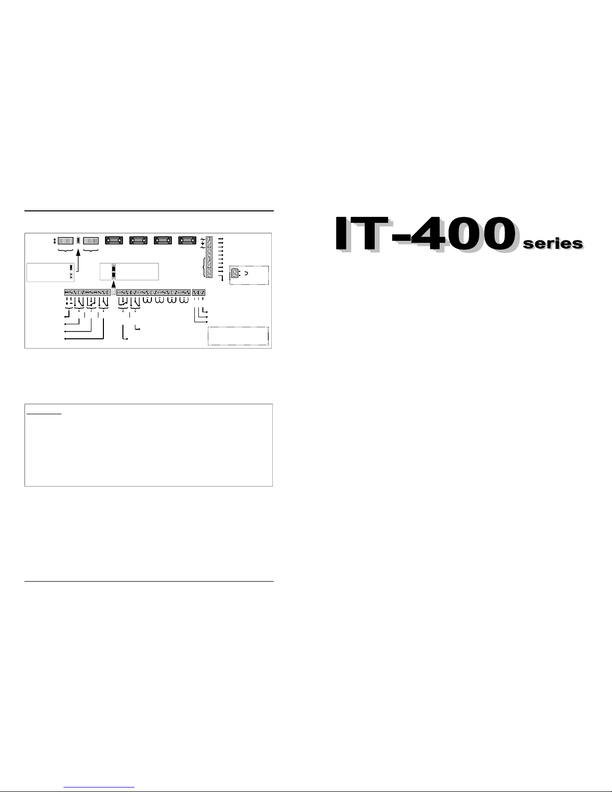
20.0 VERSION IT 400 D/K
Electronic remote key
(IT-440K version)
TS1
Volt free relay contacts
+ 12 Vdc to Terminal 14
Normally operation
Reset factory condition
F1 = 1 A
PC board
protection
F2 = 1 A
Auxiliary ou-
tputs
protection
F3 = 1 A
Battery polarity
inversion
ON
OFF
12345678
Dip-switch A
12345678
Dip-switch B
J8
F4 = 1 A
Short circuit
transformer
42
41
40
39
38
37
36
35
34
33
1 2 3 4 5 6 7 8 9 10 11
12 Vdc auxiliary output
Fire alarm relay
Panic alarm relay
Indoor siren relay
NO C NC NC NO C NO C NC
30 31 32
L1 L2 L3 L4
Bus RS485
L5 L6 L7 L8
Relay with selectable operation
12 13 14 15 16 17 18 19 20 21 22 23 24 25 26 27 28 29
Negative
L5 = Not used
L6 = Fire alarm line
L7 = Panic alarm line
L8 = 24 hours antitamper line
19 Vac
GND
19 Vac
Unit ON
Negative impulse
D
C
B
A
IT–400 / 400D version
GND
TX
RX
34
33
Normally closed lines
(NC)
Remote key
(NC)
Volt free relay contacts
NC NO C NO C NC
Outdoor siren relay
30 31 32 - RS 485 BUS, serial interface for connecting expansions and programming
peripherals.
33 34 - Normally closed Remote key input for total arming (IT-400 D)
35 36 37 - Not present on IT-400D.
IT-400 K onl
y
33 - Negative
34 - Remote electronic key input (see page 10).
35 - Output for remote LED that indicates control panel armed day position.
This is located on the remote electronic key base. (see page 10).
36 - Output for remote LED that indicates alarm memory.
This is located on the remote electronic key base (see page 10).
37 - Output for remote LED that indicates control panel armed for night functions.
This is located on the remote electronic key base (see page 10).
38 - Negative output for telephone dialler that signals burglary and tamper
(Imax 100 mA). This output remains active for one second.
39 - Negative output for "Unit ON" signalling - (Imax 100 mA).
This output remains active during the ON status.
40 42 - Power input for control panel 19 Vac.
41 - NOT USED
Summary Page
7 zone hardwire control panels
3 models IT-400/IT-400 K/IT-400 D
1.0. Description ...................................................................................................... 2
2.0. Installation ....................................................................................................... 3
3.0. Terminal block connections ........................................................................... 4
4.0. Mains power connection ................................................................................. 7
4.1. Mains power fuse change ........................................................................ 7
4.2. Ground connection ................................................................................... 7
5.0. Front panel ....................................................................................................... 8
6.0. Zone description ............................................................................................. 9
6.1 Balance resistor connection ........................................................................ 9
7.0. Key ................................................................................................................. 9
7.1 Electronic key ............................................................................................ 10
7.2. Remote receptacle installation .................................................................... 10
7.3. Electronic key sabotage ............................................................................. 10
8.0. Mechanical switch lock key ............................................................................ 11
9.0. Maintenance mode .......................................................................................... 11
10.0. Programming ................................................................................................... 12
11.0. User code ......................................................................................................... 13
12.0. Self learning of the electronic key ................................................................. 13
13.0. By-passing zones ............................................................................................ 14
14.0. Total arming (ON mode) ................................................................................. 15
15.0. Partial arming (NIGHT mode) .......................................................................... 16
16.0. Disarming (DAY mode) ................................................................................... 17
17.0. Low battery alert .............................................................................................. 18
18.0. Reset to factory code ...................................................................................... 18
19.0. Technical characteristics ................................................................................ 19
20.0 Connected Version IT 400 D/K ........................................................................ 20

Page 2 IT-400 series instruction manual
ENGLISH
The IT-400 is an elaborate hardwire control panel with 4+3 zones divided as follows:
The first 4 burglary zones are programmable and may be configured as Day, Night, normally
closed (N.C.) or balanced. Each of these zones has automatic by-pass feature which goes
into effect after 4 alarm cycles. In addition Zone 1 and Zone 2 can be configured as delayed
or immediate.
The remaining 3 zones (fire, panic and sabotage) are not programmable and always
active.
The control panels of the IT-400 series may be armed by means of a mechanical key (IT-400),
an electronic key (IT-400 K) or keypad (IT-400 D). Remote arming key is optional.
The creation of a group of zones that function in Day or Night permits you to rapidly arm the
control panel without modifying the way the panel has been programmed.
For IT-400 K only, unauthorized attempts to arm the control panel will activate the anti
-sabotage zone which will block the use of the electronic key and at the same time trigger the
alarm.
The extreme flexibility of the different programming methods allows the end user to
personalize the installation based on his needs.
Other Characteristics
Day/Night arming
Programmable relay alarm outputs
Separate relay alarm outputs for internal sirens
Remote indication for unit ON
Low battery indication
Output for siren with or without battery back up
Relay output for panic an fire.
1.0. DESCRIPTION
Congratulations for buying the IT-400, a user friendly hardwire control panel.
Every unit is assembled using the latest microprocessor technology, followed by robotic
assembly methods and computerized test, resulting in an apparatus secure and reliable.
Page 19 IT-400 series instruction manual
ENGLISH
18.0. TECHNICAL CHARACTERISTICS
Power: 230 Vac - 50 / 60 Hz
Current drain in stand by: 65 mA
Current drain in alarm : 270 mA max.
Line sensitivity: 300 milliseconds
Alarm time: 60, 120, 180 seconds or infinite (programmable)
Entry time: 15, 30 or 60 seconds (programmable)
Exit time: 30 or 60 seconds (programmable)
Relay contacts panic alarm: 1 A max
Relay contacts fire alarm: 8 A max
Relay contacts indoor siren: 8 A max
Relay contacts outdoor siren: 8 A max
SMD technology
Rechargeable battery housing: 12 V - 7 A/h max (ABS container)
12 V - 17 A/h max (metallic container)
Dimensions: 275x220x80 mm (ABS container)
310x315x80 mm (metallic container)
Weight: 1.5 Kg (ABS container)
4.9 Kg (metallic container)
Latest revision 10-02-2009
Tre i Systems is not responsible for inappropriate use of it’s products.
For any problems refer to the nearest authorized agent or directly to Tre i Systems central assistance centre
.
Page 18 IT-400 series instruction manual
ENGLISH
18.0.
RESET TO FACTORY CODE
(IT-400 K / IT-400 D )
This is an emergency procedure to be used, for example, in the case that the owner has lost
all the electronic keys (IT-400 K) or forgot the access code (IT-400 D).
1) Open the cover of the control panel and disconnect all power (both 230 Vac and 12 V
battery supply).
Note
: This will provoke a TAMPER ALARM!
2) Put to ON dip 1 of dip-switch A.
3) Re-connect the po wer to the control panel. The LEDs “ON” and “NIGHT” will flash to
indicate maintenance mode.
4) Remove bridge "J8".
5) (IT-400K onl y) - Insert the Master key and wait until the LEDs “ON”, “DAY” and “NIGHT”
fast flash twice to indicate that the master key has been memorized.
If this does not happens, repeat points 4) and 5).
6) Insert bridge "J8".
7) Exit from maintenance by putting to OFF dip 1 of dip-switch A.
8) Close the cover.
After following the above procedure all of the electronic key codes mem orised in the IT
-400K will be cancelled and the access code programmed by the user in the IT-400 D will
return to the pre-programmed factory code of 123456
and the control panel will auto-
matically set to “DAY” status.
17.0. LOW BATTERY ALERT
In case of mains failure, the power is supplied by the battery.
When the battery voltage goes below 10.5 V, the c ontrol panel will signal the event with th e
lighting of the “LOW BATTERY” LED on the panel.
The LED will remain active until the control panel is re-armed to signal "Low battery
memory".
If “LOW BATTERY” alert continues, check if the mains is present (green “POWER” LED
lit), check the mains fuse and if the battery charger is functioning correctly (+13.8 Vdc on
cables of battery). If all functions correctly, then the battery must be replaced.
Please dispose of faulty batteries in an environmental
friendly manner.
ATTENTION
Page 3 IT-400 series instruction manual
ENGLISH
For an easy and correct installation follow the steps listed below.
1) Remove the ABS control panel cover
2) Fix the base of the panel to the wall
3) Connect all the sensors and sirens to the control panel
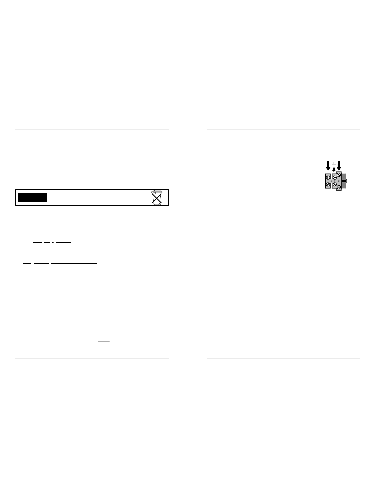
4) Connect the mains 230 Vac power source to the 3 terminals
indicated on the right. Be sure to connect a good ground source
to the centre terminal.
Be careful that the cable being connected is without tension.
5) Program the unit using dip switch A and B (see page 32).
6) Connect the battery using the red and black te rminal which indicate the polarity. Red for
positive and black for negative, you will see the “test” LED flashing. This indicates that the
control panel is in Maintenance mode.
7) Re-position and fix the control panel cover.
8) Connect the mains power input wire to a 230 Vac source. It is suggested that this power
source be obtained between the AC power meter and the main circuit breaker. After this is
done the green LED “POWER” will light up.
9) Be sure that the 24 hour anti-sabotage line is closed (red LED - 24 H OFF).
10) Set the panel in “DAY” mode. The control panel will go into disarmed status.
IT-400 : Rotate the key in “DAY” position
IT-400 K : Automatically goes to “DAY” status.
IT-400 D : Automatically goes to “DAY” status.
NOTE: When the panel has no mains and no battery voltage connected, and you power
it, the IT-400 will go to the status of the panel KEY switch, IT-400K and IT-400D will
automatically go to “DAY” status.
2.0. INSTALLATION
230 Vac
Fuse
T 800
mA
Page 4 IT-400 series instruction manual
ENGLISH
Manutenzione
Per passare da …..
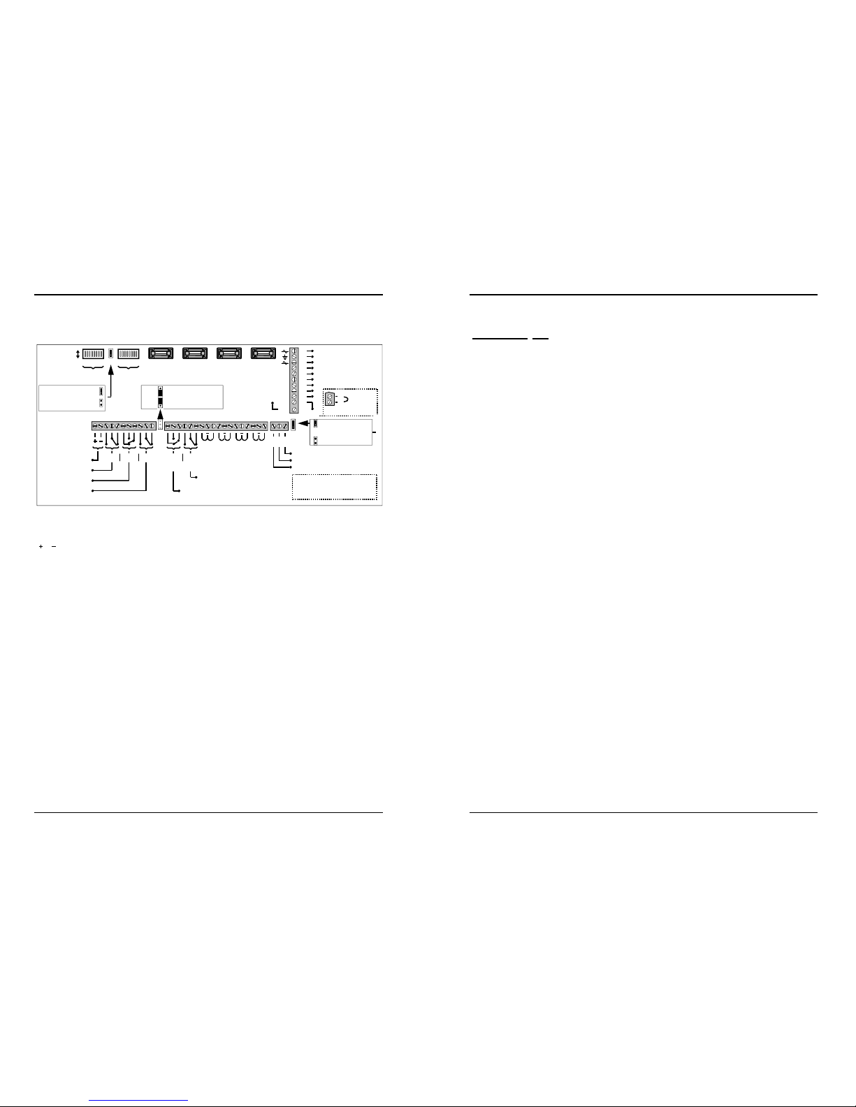
3.0. TERMINAL BLOCK CONNECTIONS
1 2 - Auxiliary output 12 Vdc - (Imax 1 A).
This output is always active with control panel armed or disarmed.
3 4 5 - Normally opened (N.O.) - Common (C) - Normally closed (N.C.) - Volt free relay
contact for fire / gas alarm (Im ax 8 Amp).This relay is activated for the programmed
time when the zone L6 is triggered.
6 7 8 - Normally closed (N.C.) - Normally opened (N.O.) - Common (C)
Volt free panic alarm relay - (Imax 1 A).
This rela y activates for 10 sec. At the opening of line L7 (panic audible / non
audible).
9 10 11 - Volt free change-over relay alarm output for internal siren - (Imax 8 A).
Normally opened (N.O.) - Common (C) - Normally closed (N.C.).
This relay is activated if burglary, sabotage, or audible panic alarms are
triggered.
12 13 14 - Volt free change-over relay alarm output for external siren - (Imax 8 A).
Normally closed (N.C.) - Normally opened (N.O.) - Common (C.).
This relay is activated if burglary, sabotage, or audible panic alarms are
triggered.
Bridging the connector TS1 as shown above, the common of the relay
(Terminal 14) is connected to +12 Vdc.
15 16 17 - Volt free change-over relay alarm output for external siren - (Imax 8 A).
Normally opened (N.O.) - Common (C) - Normally closed (N.C.).
This relay is activated if bu rglary, sabotage, or audible panic alarms are triggered.
TS1
Volt free relay contacts
+ 12 Vdc to Terminal 14
Normally operation
Reset factory condition
F1 = 1 A
PC board
protection
F2 = 1 A
Auxiliary ou-
tputs
protection
F3 = 1 A
Battery polarity
inversion
ON
OFF
12345678
Dip-switch A
12345678
Dip-switch B
J8
F4 = 1 A
Short circuit
transformer
43
42
41
40
39
38
37
36
35
34
1 2 3 4 5 6 7 8 9 10 11
12 Vdc auxiliary output
Fire alarm relay
Panic alarm relay
Indoor siren relay
NO C NC NC NO C NO C NC
30 31 32
L1 L2 L3 L4
Bus RS485
L5 L6 L7 L8
Relay with selectable operation
12 13 14 15 16 17 18 19 20 21 22 23 24 25 26 27 28 29
Negative
L5 = Not used
L6 = Fire alarm line
L7 = Panic alarm line
L8 = 24 hours antitamper line
19 Vac
GND
19 Vac
Unit ON
Negative impulse
D
C
B
A
IT–400 / 400D version
GND
TX
RX
35
34
Normally closed lines
(NC)
Remote key
(NC)
Volt free relay contacts
NC NA C NO C NC
Outdoor siren relay
33
Buzz
Remote Key Impulse
Remote Key ON/OFF
Page 17 IT-400 series instruction manual
ENGLISH
To disarm the panel:
IT-400 : Rotate the key in “DAY” position.
IT-400 K : Insert the key into the key holder for less than 5 sec.
IT-400 D : Digit the access code on a keypad and press “#”.
The panel will disarm. The LED “ON” or “NIGHT” will go off.
If while armed, an alarm has been triggered, when the control panel is disarmed, the LED
of the triggered zone will flash until the control panel is again armed. This indicates "Alarm
memory".
To cancel the alarm memory in IT-400 D / IT-400K, press any key on the keypad or change
the status of the control panel by first arming and then disarming the control panel.
To cancel the alarm memory in IT-400, it is sufficient to change the status of the control
panel by rotating the key before in "ON" position and then in "DAY" position.
16.0. DISARMING (DAY mode)
1)
The unbalancing of the 24 hour zone (Terminals 28 and 29), the sabotage of zones L1 L4
and the inserting of false electronic keys will cause
:
- Slow flashing of “24 H” LED on the panel. The LEDs will remain active until the next
arming of the panel to indicate “Alarm memory”.
- The activation of the indoor and outdoor siren alarm relays (Terminals 9 to 17) for the
time that has been programmed.
2)
The unbalancing of the fire zone (Terminals 25 and 26) causes:
- Slow flashing of the “FIRE” LED on the panel. The LEDs remain active until the next
arming of the panel to indicate “Alarm memory”.
- The activation of the fire alarm relay (Terminals 3, 4 and 5) for 30 seconds.
3)
The unbalancing of the panic zone (Terminals 27 and 28) causes:
- Slow flashing of the ”PANIC” LED on the panel. The LEDs remain active until the next
arming of the panel to indicate “Alarm memory”.
- The activation of the panic alarm relay (Terminals 5, 6 and 7) for 10 seconds.
- The activation of the indoor and outdoor siren alarm relays (Terminals 9 to 17) for the
time they have been programmed .
4)
Low battery level (load under 10.5 V) causes:
- Slow flashing of the “LOW B.” LED on the panel. The LED remain active until the next
arming of the panel to indicate “Alarm memory”.
5)
Opening of L1
L4 when functioning in N.C. or the violation of the zones (both not
excluded) will cause:
- The lighting of the LED on the panel corresponding to the triggered zone only f or the
time that the zone remains open or unbalanced.

Page 16 IT-400 series instruction manual
ENGLISH
Procedure:
IT-400 : Rotate the key to “NIGHT” position
IT-400 K : Insert the key into the key holder for more than 5 sec.
IT-400 D : Digit the access code on a keypad and press “º”
During the exit time the following will take place:
- The “NIGHT” LED on the panel and electronic key receptacle will light.
- If however there are zones open or unbalanced, the LED of the triggered zone on the
panel and the “DAY” LED on the panel and electronic key receptacle will light.
At the end of the exit time:
- The “NIGHT” LED on the panel and electronic key receptacle will flash.
- The “Alarm memory” LED on the electronic key receptacle will go off.
- The control panel is now armed in "NIGHT" mode.
1) Violation or unbalancing of the 24 hour, fire and panic zones, tampering of the
sensors installed, insertion of false electronic key and low batter y condition, will
trigger the internal and external siren volt free alarm rela y (Terminals 9,10,11 and
12,13,14,15,16,17).
2) The opening or unbalancing of one of the zones L1 L4 causes:
- Flashing on the panel of the LED corresponding to the zone triggered until the control
panel is re-armed.
- Lighting of the "DAY" LED on the panel and electronic key receptacle until the control
panel is re-armed.
- Activation of the indoor and outdoor siren alarm relays (Terminals 9 to 17) for the time
programmed.
All the zones are active except those by-passed (see paragraph 13.0.).
15.0. PARTIAL ARMING (NIGHT mode)
If when the control panel is armed there is an open or unbalanced zone
or low battery, the control
panel will arm anyway, but if the cause
persists, at the end of the exit time, the control panel will go into alarm.
ATTENTION
Page 5 IT-400 series instruction manual
ENGLISH
18 19 - L1 - Programmable Normally Closed (N.C.) immediate or delayed line.
With the control
panel armed, triggering this line will cause:
Flashing of the corresponding LED on the front panel until the control panel is
re-armed to signal Alarm memory.
Lighting of the "DAY" LED (on the front panel and on receptacle of electronic
key) until the control panel is re-armed to signal Alarm memory.
Activation of the internal siren (Terminals 9,10,11) and external siren
(Terminals 12 to 17) alarm relays for the pre-programmed time.
With the control
panel disarmed, triggering this line will cause:
Lighting of the corresponding LED on the front p anel for the time that the line
is in alarm.
What has been written above for L1 is valid for all 4 burglary alarm zones, with the only
difference that L1 and L2 can be either programmed as delayed, and immediate while
lines L3 and L4 are only immediate.
24 - Not used
25 26 - L6 - Fire or gas alarm trigger inputs.
With control
panel armed or disarmed, triggering this line will cause:
Flashing of the “FIRE” LED on the front panel until the control panel is re-armed
to signal Alarm memory.
Activation for the pre-programmed time of the fire relay
output
(Terminals 3, 4, 5).
27 28 - L7 - Hold-up alarm trigger input.
With control
panel armed or disarmed, triggering this line will cause:
Flashing of the “PANIC” LED on the front panel until the control panel is
re-armed to signal Alarm memory.
If you have programmed a silent hold-up alarm, after this alarm has been
triggered only the panic relay will activate (Terminals 6, 7, 8) for 10 seconds.
If you have chosen to program the hold-up alarm with an audible alarm signal,
triggering this alarm output will activate the hold-up alarm relay terminals 6-7-&8
for 10 seconds and also the internal and external sirens relays (Terminals 9
through 17) for the programmed alarm time.
28 29 - L8 - 24 hour anti-tamper trigger input.
With control
panel armed or disarmed, triggering this line will cause:
Flashing of the "24 H" LED on the front panel until the control panel is
re-armed to signal Alarm memory
Activation of the internal and external sirens relays (Terminals 9 through 17) for
the programmed alarm time.

Page 6 IT-400 series instruction manual
ENGLISH
30 31 32 - RS 485 BUS, serial interface for connecting expansions and programming
peripherals.
33 - The Buzzer must be connected from +12 Vcc and buzz terminal
34 35 - Normally closed Remote key input for total arming used on (IT-400 & IT-400D) only
36 37 38 - Not used on IT-400
39 - Negative output for telephone dialler that signals burglary and tamper
(Imax 100 mA). This output remains active for one second.
40 - Negative output for "Unit ON" signalling - (Imax 100 mA).
This output remains active while the panel is armed.
41 43 - Power input for control panel 19 Vac.
42 - NOT USED
FUSES
F1 = 1 A - Rapid fuse to protect the internal power supply .
F2 = 1 A - Rapid fuse to protect the auxiliary 12 Vdc outputs (Terminals 1 and 2).
F3 = 1 A - Rapid fuse to protect inversion of polarity of the battery.
F3 = 1 A - Delay action fuse to protect short circuit of the transformer.
Page 15 IT-400 series instruction manual
ENGLISH
14.0. TOTAL ARMING (ON mode)
Procedure:
IT-400 : Rotate the key in “ON” position.
IT-400 K : Insert the key into the key receptacle for less than 5 sec.
IT-400 D : Digit the access code, after which press key “#”.
During the exit time the following will take place:
- The “ON” LED on the panel and electronic key receptacle will light.
- If however there are zones open or unbalanced, the LED of the triggered zone on the
panel and the “DAY” LED on the panel and electronic key receptacle will light.
At the end of the exit time:
- The “ON” LED on the panel and electronic key receptacle will flash.
- The “Alarm memory” LED on the electronic key receptacle will go off.
- The panel is now totally armed (ON mode).
1) Violation or unbalancing of the 24 hour, fire and panic zones, tampering of the
sensors installed, insertion of false electronic key and low batter y condition, will
trigger the internal and external siren volt free alarm rela y (Terminals 9,10,11 and
12,13,14,15,16,17).
2) The opening or unbalancing of one of the zones L1 L4 causes:
- Flashing on the panel of the LED corresponding to the zone triggered until the control
panel is re-armed.
- Lighting of the "DAY" LED on the panel and electronic key receptacle until the control
panel is re-armed.
- Activation of the indoor and outdoor siren alarm relays (Terminals 9 to 17) for the time
programmed.
If when the control panel is armed there is an open or unbala nced line
or low battery, the control
panel will arm anyway, but if the cause
persists, at the end of the exit time, the control panel will go into alarm.
ATTENTION

Page 14 IT-400 series instruction manual
ENGLISH
ATTENTION
As you enter the 5th phase, the panel will show how
zone 1 (L1) is set (L1 is always “ON” or flashing).
Visualization of the c onfiguration memorized
IT-400 / IT-400K - Turn the key of the control panel to the "NIGHT" position
and during the exit time, press any one of the buttons
“A”,.“B”, “C” or “D" relative to the zones.
IT-400 D - Bring the control panel to the "NIGHT" mode by digiting the access
code followed by “
º” and during the exit time press “#”.
The control panel will visualize the present state of the zones programm e d for Nig ht a rmi ng
.
► If the LED related to the zone is lit, the zone is active in “NIGHT” mode.
► If the LED related to the zone is OFF, the zone is by-passed in “NIGHT” mode.
To modify the configuration memorized
To modify the memorized configuration, press buttons “A”, “B”, “C” or “D” related
to the zones. The LED will change status from lit to off or viceversa.
To memorize a configura tion
At the end of configuration, switch the control panel to the "DAY" mode for memorization.
IT-400 / IT-400 K - Turn the key of the control panel to the "DAY" position.
IT-400 D - Digit “#” to bring the control panel to "DAY" mode.
13.0. BY-PASSING ZONES
It is possible to partially arm the system (NIGHT mode) by by-passing some of the zones.
NOTE
The control panel is supplied with all the zones active.
Page 7 IT-400 series instruction manual
ENGLISH
One of the two phases of the mains power is protected by a
delay action fuse T800 mA.
The fuse is incorporated in the terminal block seen on the right hand
side.
In case of fuse burn out it can be easily changed by pulling
upward the fuse holder as shown on the right.
Change the fuse and plug it back in with downward pressure.
It is important to have a good ground connection to avoid electrical
disturbances to the control panel. Therefore the terminal indicated as
ground (see on the right)
must be connected to a good ground
connection.
4.0. MAINS POWER CONNECTION
Ground
connection
Presence of main power is indicated on the front panel when the green “POWER” LED lights
up.
Before making this connection be sure that cable
being use is volt free and insert the bare wire on
the cable used completely into the terminal block as
seen on the right.
Electrical building installation must be equipped with a bipolar automatic switch.
In case of ordinary maintenance, disconnect the unit from the mains.
4.1. MAINS POWER FUSE CHANGE
4.2. GROUND CONNECTION
ATTENTION
NO YES

Page 8 IT-400 series instruction manual
ENGLISH
5.0. FRONT PANEL
ARMING / DISARMING KEY
1) Model IT-400 : Mechanical key switch for arming and
disarming. The control panel may be armed also with
remote optional NC mechanical key .
2) Model IT-400 K : Electronic key for arming and disarming the control panel is supplied with the unit.
Remote electronic key is optional.
1) Model IT-400 D : Digital keypad for arming and disarming. The control panel may be armed also with
remote optional NC mechanical key.
“POWER”_LED
Always lit signals 230 Vac present.
“LOW BATTERY” LED
Control
panel disarmed or armed (Day /ON/ Night):
1) Off indicates battery charged (normal status).
2) Lit indicates low battery.
“AS” LED
With control panel disarmed or armed Day /ON/ Night:
1) Off signals line closed (normal status).
2) Flashing indicates zone in alarm or alarm memory.
L1 TO L4 ZONE LEDS
Control panel disarmed (DAY) :
1) Lit indicates line open or un-balanced.
2) Flashing indicates alarm memory.
3) Off signals line closed (normal status).
Control panel armed (ON and NIGHT):
1) Off signals line closed (normal status).
2) Lighting during the exit time signals line in alarm.
3) Flashing after the exit time signals alarm memory.
PUSH BUTTONS A-B-C-D
1) Are used to associate zones to Night status and to digit
access code (IT-400D only).
“ON” LED (on the panel and remote electronic key)
1) Lights up during the exit time, then flashes until panel is
disarmed.
“FIRE” LED
With control panel disarmed or armed Day / ON / Night:
1) Off signals line closed (normal status).
2) Flashing indicates zone in alarm or alarm memory.
“DAY” LED (on the panel and remote electronic key)
1) Flashes during the “Day” status.
2) Lighting during the exit time signals line open or un
-balanced.
3) Lighting during the “ON” and "NIGHT" status signals
alarm memory.
“Night” LED (on the panel and remote electronic key)
1) Lights up during the exit time, then flashes until panel is
disarmed.
“PANIC” LED
With control panel disarmed or armed Day / ON/ Night:
1) Off signals line closed (normal status).
2) Flashing indicates zone in alarm or alarm memory.
L.BAT.
FIREPANICAS
POWER L.BAT.
FIREPANICAS
POWER
L1
L2
L3
L4
L1
L2
L3
L4
D
C
A
B
ON
DAY
ON
NIGHT
DAY
NIGHT
Page 13 IT-400 series instruction manual
ENGLISH
Procedure for self learning code:
1) Insert the Master key for less than 5 seconds and during the exit time open the front cover
and set switch 1 of dip-switch A in ON position. The LEDs “ON” and “NIGHT” will flash to
indicate maintenance mode.
2)
Open the jumper "J8". The LED “ON”, "DAY" and “NIGHT” will light to indicate self learning
of codes. Insert a key in the front panel receptacle and wait for two fast flash of the LEDs
“ON”, "DAY" and “NIGHT”. This confirms that the key code has been read. Insert jumper
"J8" to confirm the memorization of the key.
Repeat the above procedure for all the keys to be memorized.
It is possible to memorize up to 9 keys, including the Master key.
NOTE: If you try to memorize a previously memorized key the panel will not use a new
location of memory, only the flashing of LED “ON”, "DAY" and “NIGHT” will happen.
If all the 9 memory locations have been occupied, the panel will not accept new
keys. In this case t he master key (as explained in paragraph 18.0.) and all the
available keys must be re-programmed as described above.
The control panel can learn up to 9 different
electronic key codes.
The control panel is supplied with factory programmed code of “123456”.
This code can be modified using the following procedure:
With the control panel in "DAY" mode, digit:
“# existing code # new code #”
This code may be made-up from a minimum of 1 and a maximum of 6 digits (from numbers
between 0 and 9).
If you forget the user code, it is possible to “Reset to factory code” (see paragraph 18.0.).
The panel is supplied with 2 keys already memorized. One of these is
the master ke
y, which is the only key that allows you to go into
maintenance mode and program other keys in the memory. If the
Master key is lost the “reset to factory defaults” procedure must be done (see paragraph 18.0.).
Receptacle
on front panel
11.0. USER CODE (IT-400 D only)
12.0.
SELF LEARNING OF ELECTRONIC KEY (IT-400 K only)
Page 12 IT-400 series instruction manual
ENGLISH
10.0. PROGRAMMING
With the control panel in maintenance mode it is possible to program it using dip-switches A
and B as listed below:
DIP-SWITCH A - OPTIONS
1 ON = Sets control panel in maintenance mode. OFF = Sets normal functioning.
2 ON = Exit time 60 sec. OFF = Exit time 30 sec.
3 - 4 Entrance time Zone 1
OFF- OFF = Immediate
OFF- ON = Entrance time: 15 sec.
ON-OFF = Entrance time: 30 sec.
ON-ON = Entrance time: 60 sec.
5 - 6 Entrance time Zone 2
OFF-OFF = Immediate
OFF-ON = Entrance time: 15 sec.
ON-OFF = Entrance time: 30 sec
ON-ON = Entrance time: 60 sec
7 Automatic zone exclusion after 4 alarm c
ycles - OFF = NO ; ON = YES
8 Silent or audible
panic - OFF = silent ; ON = audible
DIP-SWITCH B
- OPTIONS
1 ON = Fire relay follows the timing of the indoor siren
OF F = Fire relay blocks only when the control panel is disarmed (DAY)
2 ON = External siren has only one alarm cycle
OF F = External siren completes all alarm cycles
3 - 4 Indoor siren alarm time
OFF-OFF = Persistent sound
OFF-ON = Alarm time: 1 min.
ON-OFF = Alarm time: 2 min.
ON-ON = Alarm time: 3 min.
5 - 6
External siren alarm time (never more than that programmed on the indoor siren)
OFF-OFF = Persistent sound
OFF-ON = Alarm time: 1 min.
ON-OFF = Alarm time: 2 min.
ON-ON = Alarm time: 3 min.
7 - 8
Programming of lines L1-L2-L3-L4 (burglary) and L6-L7-L8 (fire, hold-up and tamper)
OFF-OFF = All lines disabled
OFF-ON = Lines normally closed NC
ON-OFF = Balanced lines (end of line resistor 4K7 Ohm necessary)
ON-ON = NOT USE
At the end of programming, close the cover of the control panel making sure that dip 1
of dip-switch A is in OFF position (normal function) and that the tamper button is closed.
Page 9 IT-400 series instruction manual
ENGLISH
ATTENTION
For the alarm to be triggered the line must remain open for more then 0,3 seconds.
6.0. ZONE DESCRIPTION
The series IT-400 control panels (It-400, IT-400 K, IT-400 D) have 7 zones in total of which L1
L4 are burglary alarm zones and L6, L7, L8 are Fire, panic and anti-sabotage.
All 7 zones (Terminals 18 to 23 and 25 to 29) can be programmed through the dip-switch
as normally closed (NC) or balanced with end of line resistance 4.7 K ohm.
The first 2 burglary zones, L1
L2 (Terminals 18,19,20) may be programmed either as
delayed or immediate, while L3
L4 (Terminals 21,22,23) are only immediate.
The remaining 3 zones, anti-sabotage, fire and hold-up (Terminals 23,24,25,26,27,28,29)
are always active.
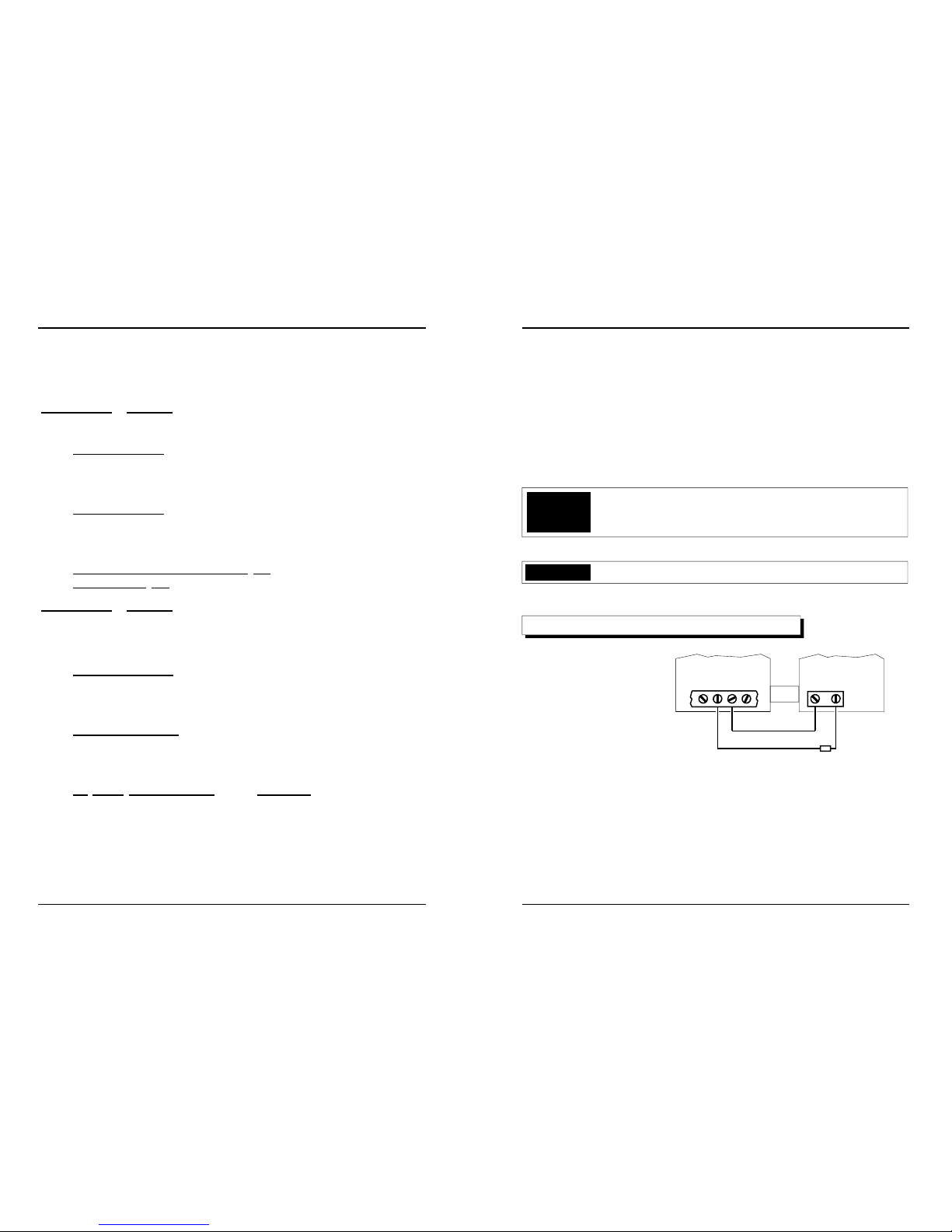
ATTENTION
If the control panel is programmed using end of line resistors you
must place a resistor of 4.7 K ohm in series with the sensors
installed. If the value of this resistor is changed (for example short
circuit), the panel will trigger an alarm.
Note the location of 4K7
end of line resistor (see
the figure on the right).
6.1. BALANCE RESISTOR CONNECTION
Control Panel
Sensor
Alarm output
zone (NC)
Balanced line
R = 4.7 K ohm
7.0. KEY
The IT-400 / IT-400 K may be armed and disarmed through the key situated on th e front pan el,
or with a code made of up to 6 digits (IT-400 D only). Remote arming is possible through
remote electronic key (optional available only for IT-400K that incorporates on board the
electronic key interface) or you may use any form of NC key switch with IT-400 and IT400 D.

Page 10 IT-400 series instruction manual
ENGLISH
The control panel is protected against attempts to insert a false electronic key.
If a person inserts a wrong key 10 times, the internal siren relay (Terminals 9,10,11) and
external siren relay (Terminals 12,13,14,15,16,17) will be triggered for the alarm time
programmed.
7.3. ELECTRONIC KEY SABOTAGE
(IT-400 K only)
The IT-400 K may be armed and disarmed through the
electronic key situated on the front panel or with a remote
electronic key (optional). The control panel is supplied
with 2 electronic keys already coded .
The control panel can self learn and memorize up to 8
different codes. Available upon request there are also
receptacles for electronic key series Magic and Living.
On the recept acle there are 3 LEDs that signal control
panel full armed “On mode”, partially armed “Night mode”
and “DAY mode” (see figure on the right).
LED "Control panel armed ON" (Red)
Has the same functions as LED “ON
” on the panel.
When the electronic key is inserted, the LED emits the
following signal:
1) Lit during exit time, after exit time has expired
flashes until panel is disarmed.
LED "Control panel armed Night mode” (Red)
Has the same functions as LED “NIGHT
” on the panel.
When the electronic key is inserted, the LED emits the following signal:
1) The LED will flash at the end of the exit time until panel is disarmed.
LED "DAY mode and Alarm Memory" (Green)
1) When control panel is in "DAY" mode, the LED flashes.
2) This LED will light during the exit time if one of the 7 zones is triggered.
3) After an alarm trigger, this LED will light and remain lit until the control panel is
disarmed and re-armed. This is indication of alarm memory.
7.2. REMOTE RECEPTACLE INSTALLATION
To allow arming of the control panel from more then one
remote position it is necessary to wire up to terminals
33, 34, 35, 36 and 37 of the IT-400 K to the terminals on
the back side of the receptacle as shown in the figure on
the right.
Control
panel
armed
ON
Control panel
armed Night
Remote
receptacle
Electronic
key
Control panel
disarmed
(DAY) and
alarm mem-
Receptacle
on front panel
7.1. ELECTRONIC KEY (IT-400 K only)
Terminal block
of the control
panel
rem oto
Inseritore
33 37363534
Page 11 IT-400 series instruction manual
ENGLISH
8.0. MECHANICAL SWITCH LOCK KEY (remote)
The IT-400 and IT-400 D may be remote armed/disarmed by means of a switch lock
connected to terminals 33 and 34.
Using a remote switch lock only total arming/disarming is possible (ON position and
Day position). Ni
ght arming is not possible.
If the control panel has been armed with a remote mechanical switch lock (Terminals
33 and 34 open), it is possible for the control panel to be disarmed by means of the
front panel key (or numeric code for IT-400 D) or the remote switch lock.
If the control panel has been armed with the front panel key or by numeric code (IT
-400 D) and you attempt to change the status with the remote sw itch lock, the control panel will not respond anymore to the remote switch lock.
9.0. MAINTENANCE MODE
With the control panel in this mode it is possible to:
1) O
pen the control panel without triggering an alarm
2) Re-set to factory codes (IT-400 K and IT-400 D onl y)
3) Enter into the
programming mode
To enter into Maintenance
With cover open: Set switch 1 of dip switch A to ON for programming. The LED “ON”
and “NIGHT” will flash to indicate maintenance mode.
With cover closed
(panel already installed): Set the panel in ON mode (with the master
key in IT-400 K) and during the exit time open the cover and set
switch 1 of dip-switch A to ON for programming. The LED “ON” and
“NIGHT” will flash to indicate maintenance mode.
To exit Maintenance mode
Finished the maintenance operations set switch 1 of dip-switch A to OFF and during the
exit time close the cover and set the panel in "DAY" mode.
NOTE: If at the end of the exit time the panel key is still in ON mode, it will automatically
arm.
 Loading...