

Pag. 1 DUALCOM-8 INSTALLATION MANUAL
ENGLISH
Dualcom-8
Remote control Alarm and Home
Automation panel with
Incoporated Telephone dialler
GSM and PSTN
Installation Manual
TRE i SYSTEMS S.r.l.
Via del Melograno N. 13 - 00040 Ariccia, Roma Italy
Tel:+39 06 97249118 Fax: +39 06 45557618
e-mail m.tomasino@treisystems.com Website: www.treisystems.com

Pag. 2 DUALCOM-8 INSTALLATION MANUAL
ENGLISH
Summary Page
Description and General characteristics ................................................................................. 3
Description of functions ........................................................................................................ 4
Keypad description ................................................................................................................ 6
Connections between control panel and keypad ..................................................................... 6
Description of keypad LEDs ................................................................................................. 7
Description of keypad commands ......................................................................................... 7
Description of the SMS commands and there remote interrogation………………………..……8
Programming the Dualcom-8 ................................................................................................ 9
Navigation with-in the programming menu .................................................................................. 10
To exit the programming mode............................................................................................ 10
00. To enter into programming mode ................................................................................... 11
01. Password management .................................................................................................. 11
02. Management of telephone numbers ............................................................................... 15
03. Management of the hardwire zones ................................................................................ 18
04. Management of the wireless zones ................................................................................. 21
05. Management of the hardwire zones related to the alarm transmission ............................ 24
06. Management of the wireless zones related to the alarm transmission .............................. 26
07. Management for event transmission to the memorized telephone numbers ..................... 28
08. Control monitoring station (CMS) management ........................................................... 30
09. SMS message management ........................................................................................... 33
10. Self learning of wireless sensor and keychain transmitters. ............................................. 35
10.5 Self learning of the wireless outdoor siren code……………………………………………39
10.6 Self learning of electronic key SK-8 .............................................................................. 40
11. Management of the memorized voice messages .............................................................. 41
12. Additional settings ......................................................................................................... 43
13. Weekly management of the installation .......................................................................... 52
14. Weekly management of the installed home automation system ....................................... 55
15. Visualize the alarm event log .......................................................................................... 58
16. Visualize the event failure log ......................................................................................... 59
17. Visualize the ARM/DISARM event log ........................................................................ 60
99. Return the control panel to factory setting ...................................................................... 61
Technical characteristics ..................................................................................................... 61
APPENDIX A .................................................................................................................... 62
APPENDIX B ..................................................................................................................... 63
APPENDIX C .................................................................................................................... 63

Pag. 3 DUALCOM-8 INSTALLATION MANUAL
ENGLISH
Description
TRE I SYSTEMS thanks you for having selected the new concept dual communication control
panel for the protection of your home, business and belongings. The DUALCOM-8 offers the end
user the most modern data transmission technology present in today's market. With the installation
of this new concept control panel, it is possible in real time to request and send all information collected, to remote telephone numbers. The control panel also offers the end user the features of two
separate areas of protection, remote arm and disarm and home automation with possibility of weekly
management. All information is transmitted on either the PSTN or GSM network or if desired both.
Though remote SMS message commands or by PSTN telephone commands, the HA-3, optional
home automation module, allows you to set, arm or disarm of any home appliance.
This panel is also compatible with the standard alarm receive station that functions with ADEMCO
4+2 and CONTACT ID protocol transmission.
The standard DUALCOM-8 control panel is manufactured with 8 programmable burglary alarm hardwire zones and 3 additional hardwired zone for Hold-up, Medical Distress, Fire and Tamper alarm
triggers. Through an optional EZ-8 expansions module (maximum 2 for each panel) the programma ble hardwire zones may be increased to maximum 24. Eight standard, plus 8 for each EZ-3 module.
In addition the standard DUALCOM-8 has on-board an additional 48 wireless zones compatible with
the “PEGASO” transmission protocol.
With the DUALCOM-8 all zones may be grouped into two AREAS of protection and programmable
with access on 6 levels of security using up to 8 different operators offering a form of higher and
more intelligent level of installation security. Each operator will be assigned a personalized access
code, keychain transmitter PEG-3, and electronic key SK-8 (see section C on Page 63).
KP-8R, the DUALCOM-8 remote keypad, has incorporated a new generation TRANSCEIVER GW
TRANSK 1120
®
module compatible with “PEGASO” transmission protocol which guarantees the
maximum transmission range between the control panel, wireless trigger sensors and the wireless
sirens TLM-18 VRP, TLM-21 VRP and TLM-7 SOLARIS.
General Characteristics:
• Areas: Maximum 2 with assigned sensors for each area.
• Hardwire zones: Minimum 8 (expandable to maximum 24 with the expansion module EZ-8)
• Wireless zones: 48 (compatible with the “PEGASO” protocol)
• Service zones: 3 (Hold-up, Medical Distress and Fire) plus 1 zone for Tamper.
• Supports hardwire sirens: ELIMINATOR-12, TLM-13F, TLM-30F, TLM-18, SB-2, TLM-39
• Supports wireless sirens: TLM-18 VRP, TLM-21VRP , TLM-7 SOLARIS (PEGASO protocol)
• Supports keypads: KP-8R and KP-8 (Maximum of 8 for each installation)
• Telephone dialler: One PSTN + One GSM with QUECTEL M10
®
• Communication Protocol: standard, ADMECO 4+2 and CONTACT ID
• Weekly management features:
∗ Automatic arm disarm:
→ Programming in DAY mode - one for each Area of protection.
→ Programming in NIGHT mode - one for each Area of protection
Home automation Arm/Disarm through optional module HA-3
→ OUTPUT 1: Can be armed or disarmed 3 times each day.
→ OUTPUT 2: Can be armed or disarmed 3 times each day.
→ OUTPUT 3: Can be armed or disarmed 3 times each day.
• Event memory capacity:
∗ Access to control panel (40 events)
∗ Alarm memory (50 events)
∗ Fault memory (50 events)

Pag. 4 DUALCOM-8 INSTALLATION MANUAL
ENGLISH
Terminal Description of function
1-2
PSTN TELEPHONE LINE INPUT (FROM THE NORMAL TEL. LINE)
3-4
PSTN TELEPHONE LINE OUTPUT TO CONNECT TO NORMAL TELEPHONE
5-6
NORMALLY OPEN HOLD-UP INPUT
7-8
NORMALLY OPEN MEDICAL DESTRESS OR EMERGENCY INPUT
8-9
NORMALLY OPEN FIRE ALARM INPUT
10-11
PROGRAMABLE HARDWIRE ZONE INPUT 1 (normally closed)
11-12
PROGRAMABLE HARDWIRE ZONE INPUT 2(normally closed)
13-14
PROGRAMABLE HARDWIRE ZONE INPUT 3
14-15
PROGRAMABLE HARDWIRE ZONE INPUT 4
16-17
PROGRAMABLE HARDWIRE ZONE INPUT 5
17-18
PROGRAMABLE HARDWIRE ZONE INPUT 6
19-20
PROGRAMABLE HARDWIRE ZONE INPUT 7
20-21
PROGRAMABLE HARDWIRE ZONE INPUT 8
22-26
BUS FOR ELECTRONIC ARMING KEY: 22=DAY LED; 23=MEMORY LED;
24=NIGHT LED; 25=GROUND; 26=KEY INPUT
27-29
BUS FOR KEYPAD: 27=DATA; 28=GND; 29=AUX+
30-32
BUS FOR EXTENTION PCB.: 30= DATA; 31= GND; 32=AUX+
Fig.1
Terminal Description of function
1-2
PSTN TELEPHONE LINE INPUT (FROM THE NORMAL TEL. LINE)
3-4
PSTN TELEPHONE LINE OUTPUT TO CONNECT TO NORMAL TELEPHONE
5-6
NORMALLY OPEN HOLD-UP INPUT
7-8
NORMALLY OPEN MEDICAL DESTRESS OR EMERGENCY INPUT
8-9
NORMALLY OPEN FIRE ALARM INPUT
10-11
PROGRAMABLE HARDWIRE ZONE 1
11-12
PROGRAMABLE HARDWIRE ZONE 2
13-14
PROGRAMABLE HARDWIRE ZONE 3
14-15
PROGRAMABLE HARDWIRE ZONE 4
16-17
PROGRAMABLE HARDWIRE ZONE 5
17-18
PROGRAMABLE HARDWIRE ZONE 6
19-20
PROGRAMABLE HARDWIRE ZONE 7
20-21
PROGRAMABLE HARDWIRE ZONE 8
22-26
BUS FOR ELECTRONIC ARMING KEY: 22=DAY LED; 23=MEMORY LED;
24=NIGHT LED; 25=GROUND; 26=KEY INPUT
27-29
3 WIRE BUS FOR KEYPAD: 27=DATA; 28=GND; 29= OUTPUT + 12V
30-32
BUS FOR 8 ZONE EXTENTION MODULE: 30
= DATA; 31= GND; 32=POWER + 12V
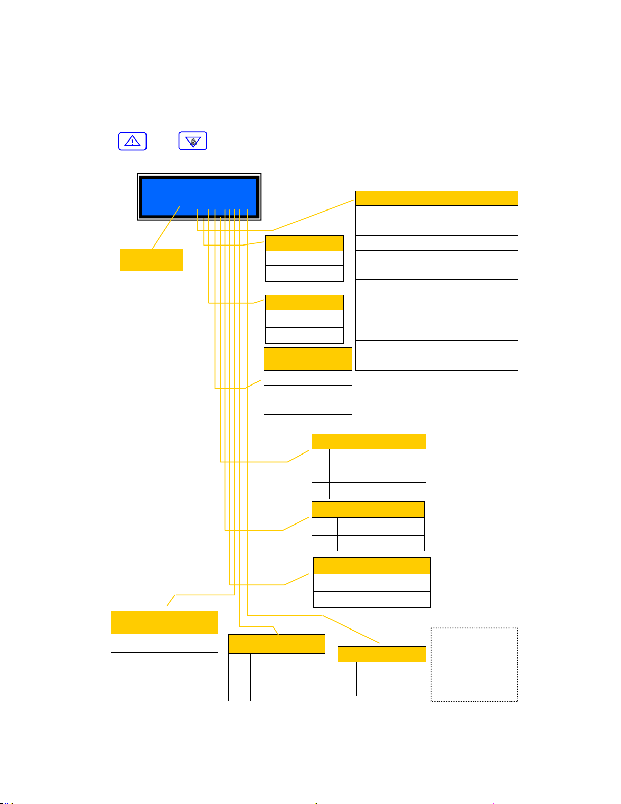
Pag. 5 DUALCOM-8 INSTALLATION MANUAL
ENGLISH
TERMINALBLOCKDISCRIPTION
JUMPERDISCRIPTION
LEDDISCRIPTION
OTHERDISCRIPTIONS
Terminal Description of function
33-35
DRY CONTACT RELAY OUTPUTS (IN ALARM): 33=Normally open;
34= Common; 35= Normally closed.
36-37
SIREN OUTPUT: 36= +12V (in alarm); 37= GROUND
38-39
PTC PROTECTED +12Vdc POWER OUTPUT: 38= +12V; 37=GROUND
40-41
SWITCHING POWER SUPPLY INPUT: 40= + 14.8Vd.c. ; 41=GROUND
42
MICRO USB PORT
JUMPER Discription and functions
43
IF BRIDGE IS “ON”, TERMINAL 34 WILL HAVE +13.8 Vdc.
54
CONTROL PANEL NORMALLY CLOSED TAMPER SWITCH= WHEN OPEN,
AN IMMEDIATE TAMPER TRIGGER WILL TAKE PLACE.
56
RESET JUMPER: IF THIS JUMPER IS INSERTED FOR 10 SECONDS, THE CONTROL PANEL WILL AUTOMATICLY RETURN TO FACTORY DEFAULT
LED Description and functions
47
GSM COMMUNICATION LED: IF “ON” = INITIALIZATION TAKING PLACE
IF “FLASHING” = FUNCTIONING NORMALLY
IF “OFF” = INDICATES MALFUNCTION
52
CPU LED: IF “ON” = INITIALIZATION TAKING PLACE
IF “FLASHING” = NORMAL FUNCTIONING MODE
IF “OFF” = INDICTES MALFUNCTION
55
COMUNICATION LED : IF “ON” = INITIALIZATION TAKING PLACE
IF “FLASHING” = NORMAL FUNCTIONING MODE
IF “OFF” = INDICATES MALFUNCTION
Other Description and functions
44
BATTERY CHARGING CABLE
45
BATTERY PROTECTION FUSE: 3.15Amp.
46
SIM CARD SOCK ET
48
SMA CONNECTOR FOR GSM ANTENNA
49
MICROPHONE FOR THE RECORDING OF VOICE MESSAGES
50
LOUD SPEAKER CONNECTOR FOR MESSAGE PLAYBACK
51
MICROPHONE AUDIO INPUT CONNECTOR FOR “LISTEN-IN FUNCTION”
Pag. 6 DUALCOM-8 INSTALLATION MANUAL
ENGLISH
DUALCOM-8
Terminal blocks
+12V
GND
DATA
29
28
27
12V DATA
GND
ON DIP
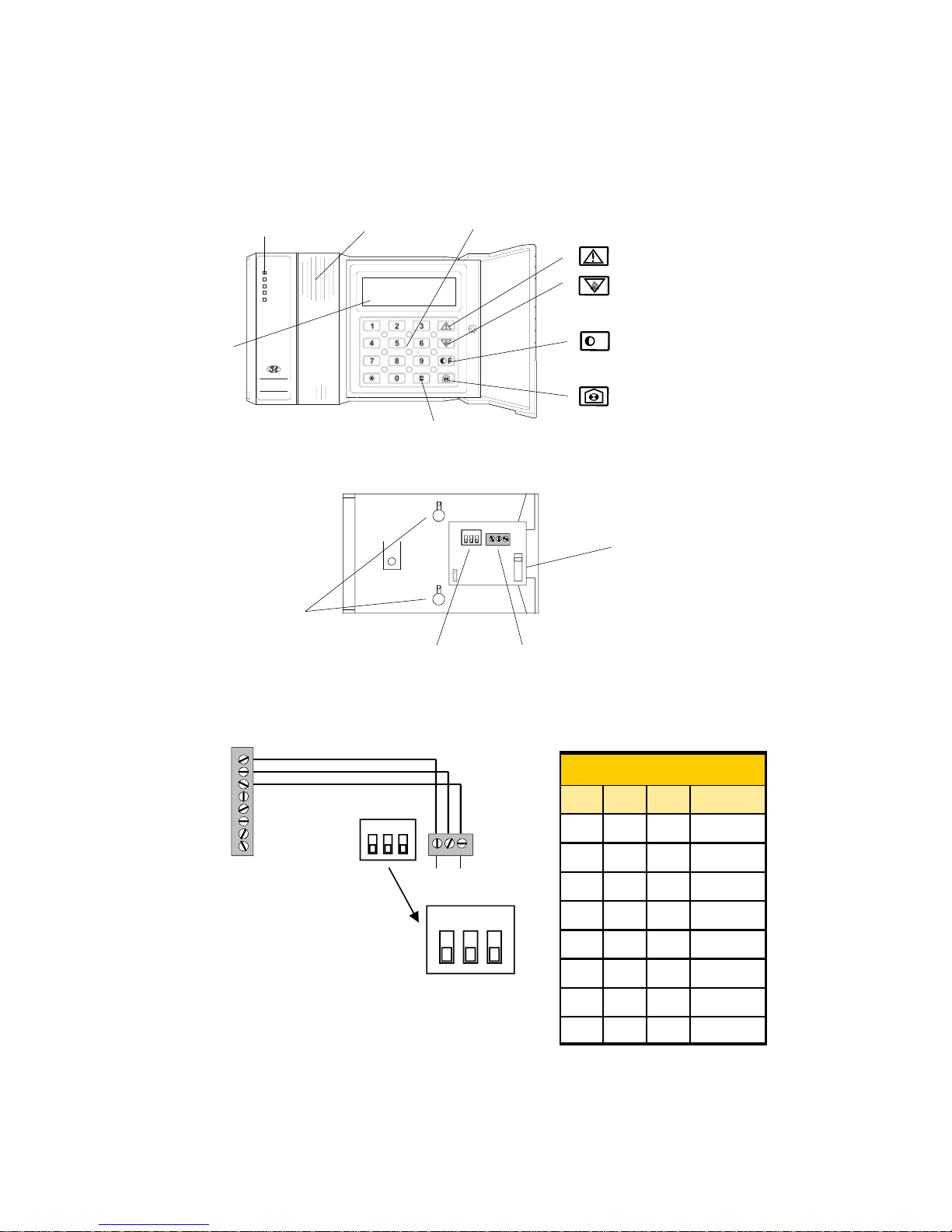
Keypad Description:
Connections between keypad and control panel:
Fig. 3
Keypad
terminal block
ON DIP
1 2 3
OFF OFF OFF
DIP SWITCH
OFF OFF ON
OFF ON OFF
OFF ON ON
ON OFF OFF
ON OFF ON
ON ON OFF
CHANNEL
1
2
3
4
5
6
7
ON ON ON 8
1 2 3
DIP SWITCH FUNCTION:
If the installation has more than
one keypad installed, each
keypad must be coded differently
with the dip switch. (see fig. 5)
Fig. 4
Fig. 5
Terminal block for
control panel connection
Keypad back side
view
Dip Switch
Wall mounting holes
Keypad Tamper
Switch
Digit-KD
UNIT ON
TAM PE R
FIRE
LOW BA T.
TEST
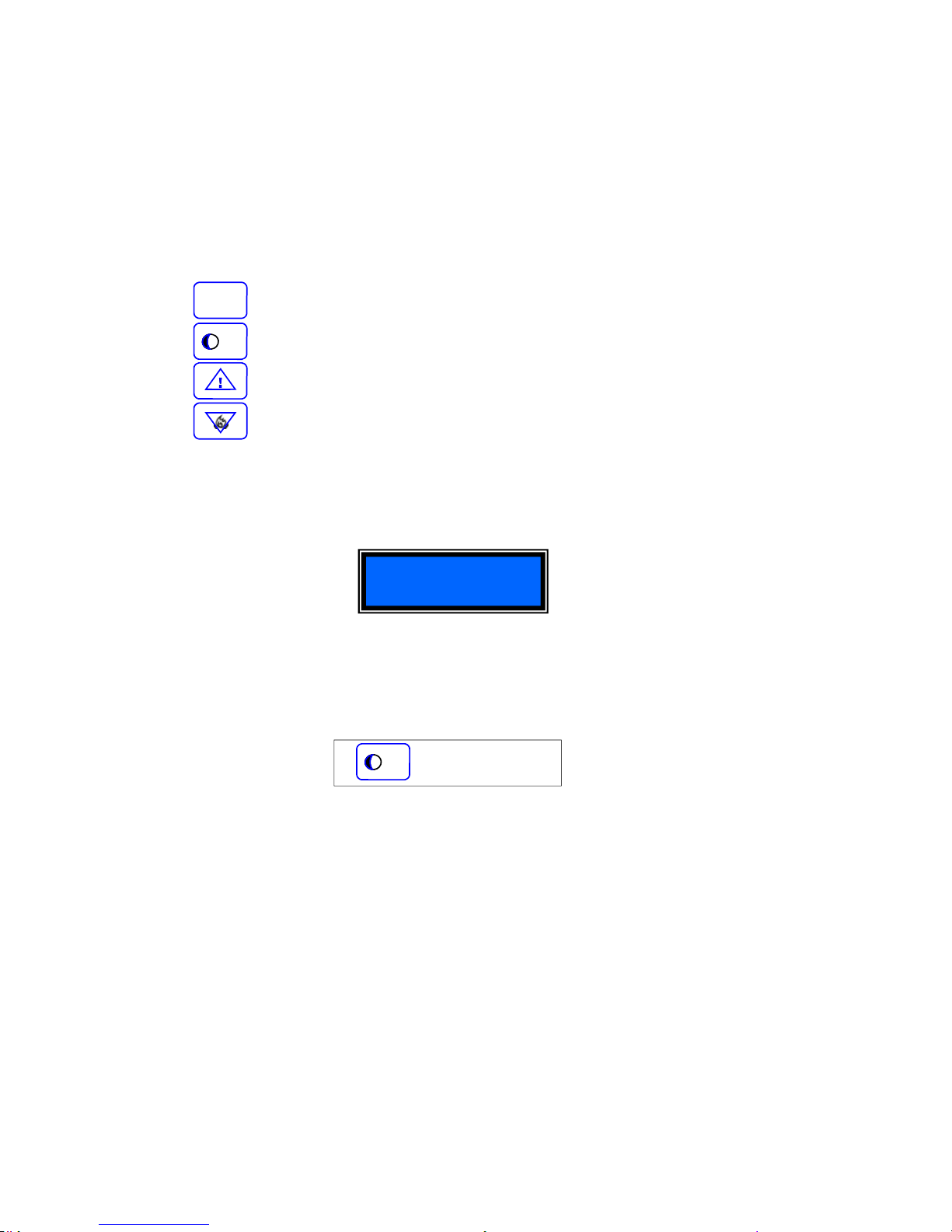
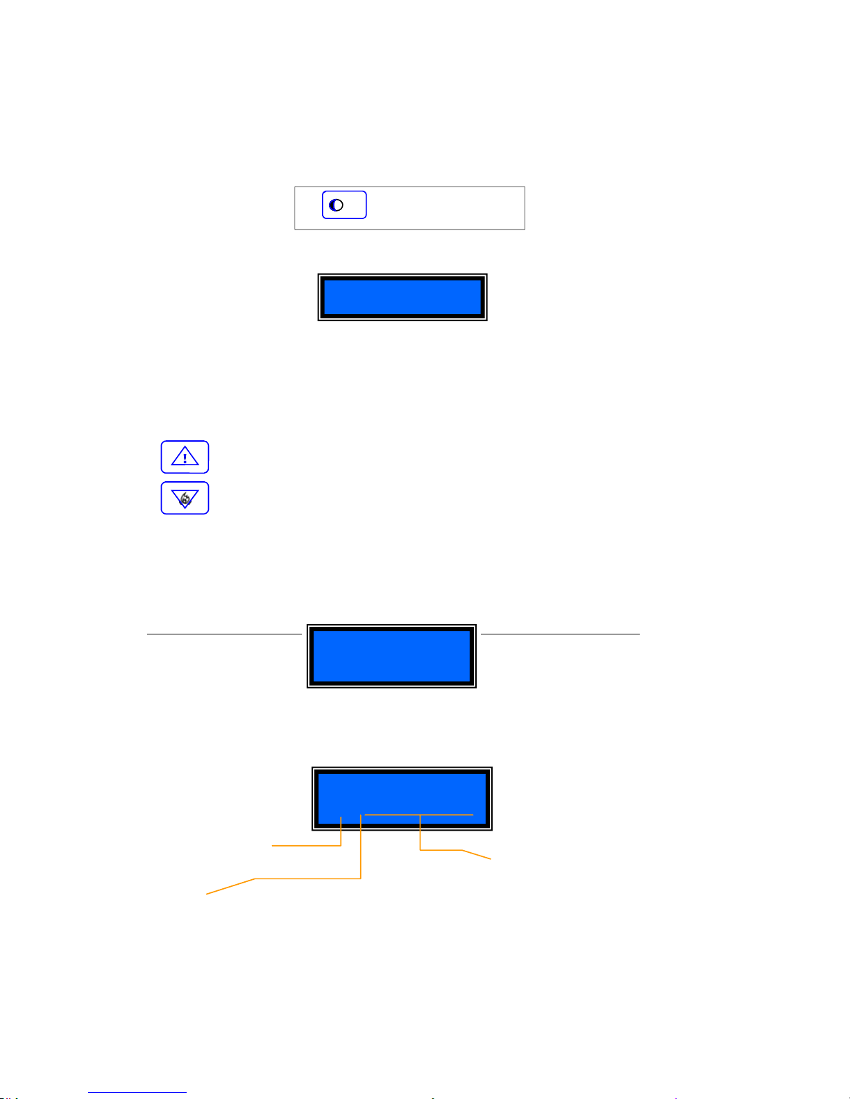
Buttons used for menu flow
Note: These buttons maybe as
seen below.
Menu “up” & Emergency
Menu “down” & Fire
Programming Function
and Hold-up button
Zone Bypass and
Chime function button
Optical
Signals (*)
Keypad buttons
Display
LCD
POWER
TAMPER
FIRE
AREA1/2
ALARM1/2
DUALCOM
Confirmation button
Buzzer
Fig. 2
F
Pag. 7 DUALCOM-8 INSTALLATION MANUAL
ENGLISH
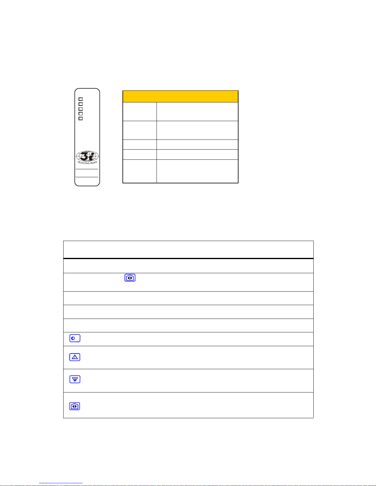
DUALCOM
POWER
AREA 1/2
TAMPER
FIRE
ALARM 1/2
POWER
“ON” = POWER CONNECTED
“OFF” = NO POWER CONNECTED
“FLASHING” = LOW BACK-UP BAT.
AREA 1/2
RED = AREA 1 ARMED
GREEN = AREA 2 ARMED
ORANGE = AREA 1 + 2 ARMED
TAMPER
“ON” = TAMPER ALARM TRIGGER
LED INDICATIONS
FIRE
“ON” = FIRE ALARM TRIGGER
ALARM 1/2
“RED” = AREA 1 IS TRIGGERED
“GREEN” = AREA 2 IS TRIGGERED
“ORANGE” = AREAS 1+2 ARE BOTH
TRIGGERED
Description of keypad LEDs
Fig. 5
NOTE: These indication
are necessary for fast
recognition and as a
support for those indicated
on the display.
Brief description of display programming commands
** see security level descriptions on page 12.
Command Sequence Function Note
[operator] [operator password ] [function]
[#]
ARM / DISARM ARM/ DISARM OR EXIT TIME
[operator] [operator password][ ]
[zone to bypass] [#]
ZONE WILL BE BYPASSED ALL ZONE MUST BE NUMBERED
WITH 2 DIGIT, FROM 01 TO 72.
EXAMPLE: FOR ZONE 4 PRESS 04
[password operator master] [*] [6] [8] [#]
GENERAL RESET - ALL ALARMS
TRIGGERED WILL STOP
ONLY LEVEL 5** OPERATOR MAY
ENTER THIS MODE
[password installer] [*] [0] [#]
USED TO ENTER INTO
PROGRAMMING MODE
ONLY INSTALLERS MAY ENTER
INTO PROGRAMMING MODE
[password operator 1] [*] [0] [#]
USED TO CHANGE THE OPERATORS
PASSWORD
ONLY LEVEL 5* OPERATOR MAY
CHANGE THE PASSWORDS.
[ ] [*] [#]
USED TO EXIT PROGRAMMING
MODE
THIS WILL FUNCTION ONLY IF YOU
ARE IN PROGRAMMING MODE
PANIC OR EMERGENCY TRIGGER PRESS KEY FOR 3 SECONDS. THIS
WILL FUNCTION ONLY IF KEYPAD
HAS BEEN PROGRAMMED TO
ACCEPT THE COMMAND
FIRE TRIGGER PRESS KEY FOR 3 SECONDS. THIS
WILL FUNCTION ONLY IF KEYPAD
HAS BEEN PROGRAMMED TO
ACCEPT THE COMMAND
HOLD-UP TRIGGER PRESS THE KEY FOR 3 SECONDS.
THIS WILL FUNCTION ONLY OF THE
KEYPAD HAS BEEN PROGRAMMED
TO ACCEPT THE COMMAND
F
Pag. 8 DUALCOM-8 INSTALLATION MANUAL
ENGLISH
Brief description of the SMS remote command messages
∗ Type of arming: 1=Day ; 2=Night
Description of the interrogation commands
from remote telephone keypad GSM or PSTN
Description of how to manage an alarm
trigger call
EVENT COMMAND
TO ACTIVATE THE LISTEN-IN FUNTION IMMEDIALY AFTER A
VOICE MESSAGE HAS BEEN HEARD
PRESS [1] [1] ON YOUR
TELEPHONE
TO HEAR ONCE AGAIN THE VOCE MESSAGE.
PRESS [2] [2] ON YOUR
TELEPHONE
TO END THE CALL AND HAVE THE DUALCOM-8 PROCEED
WITH THE DIALLER COMMUNICATION FUNCTIONS
PRESS [5] [5] ON YOUR
TELEPHONE
Function Remote command message
LISTEN-IN FUNCTION
[OPERATORS CODE] [OPERATORS PASSWORD] [0]
[#]
ARMING IN DAY MODE
[OPERATORS CODE] [OPERATORS PASSWORD] [1]
[#]
ARMING IN NIGHT MODE
[OPERATORS CODE] [OPERATORS PASSWORD] [2]
[#]
DISARMING
[OPERATORS CODE] [OPERATORS PASSWORD] [3]
[#]
ACTIVATION OF RELAY 1 TO “ON”
[OPERATORS CODE] [OPERATORS PASSWORD] [4]
[#]
ACTIVATION OF RELAY 2 TO “ON”
[OPERATORS CODE] [OPERATORS PASSWORD] [5]
[#]
ACTIVATION OF RELAY 3 TO “ON”
[OPERATORS CODE] [OPERATORS PASSWORD] [6]
[#]
ACTIVATION OF RELAY 1 TO “OFF”
[OPERATORS CODE] [OPERATORS PASSWORD] [7]
[#]
ACTIVATION OF RELAY 2 TO “OFF”
[OPERATORS CODE] [OPERATORS PASSWORD] [8]
[#]
ACTIVATION OF RELAY 3 TO “OFF”
[OPERATORS CODE] [OPERATORS PASSWORD] [9]
[#]
FUNCTION SMS MESSAGE THAT MUST BE SENT
TO ARM PANEL
[OPERATOR CODE][OPERATOR PASSWORD] [TYPE OF ARMING]
ARM
TO DISARM PANEL [OPERATOR CODE ][OPERATOR PASSWORD] DISARM
BY-PASS ZONE [OPERATOR CODE][OPERATOR PASSWORD] BYPASS [ZONE NO.]
INSTALLATION STATUS [OPERATOR CODE ][OPERATOR PASSWORD] STATUS
RELAY ACTIVATION [OPERATOR CODE ][OPERATOR PASSWORD] RELAY ON [RELAY NO.]
RELAY DISACTIVATION
[OPERATOR CODE ][OPERATOR PASSWORD] RELAY OFF [RELAY
NO.]

Pag. 9 DUALCOM-8 INSTALLATION MANUAL
ENGLISH
PROGRAMMING
THE DUALCOM-8
CONTROL PANEL
WITH THE KP-8 OR KP-8R
KEYPAD
Pag. 10 DUALCOM-8 INSTALLATION MANUAL
ENGLISH
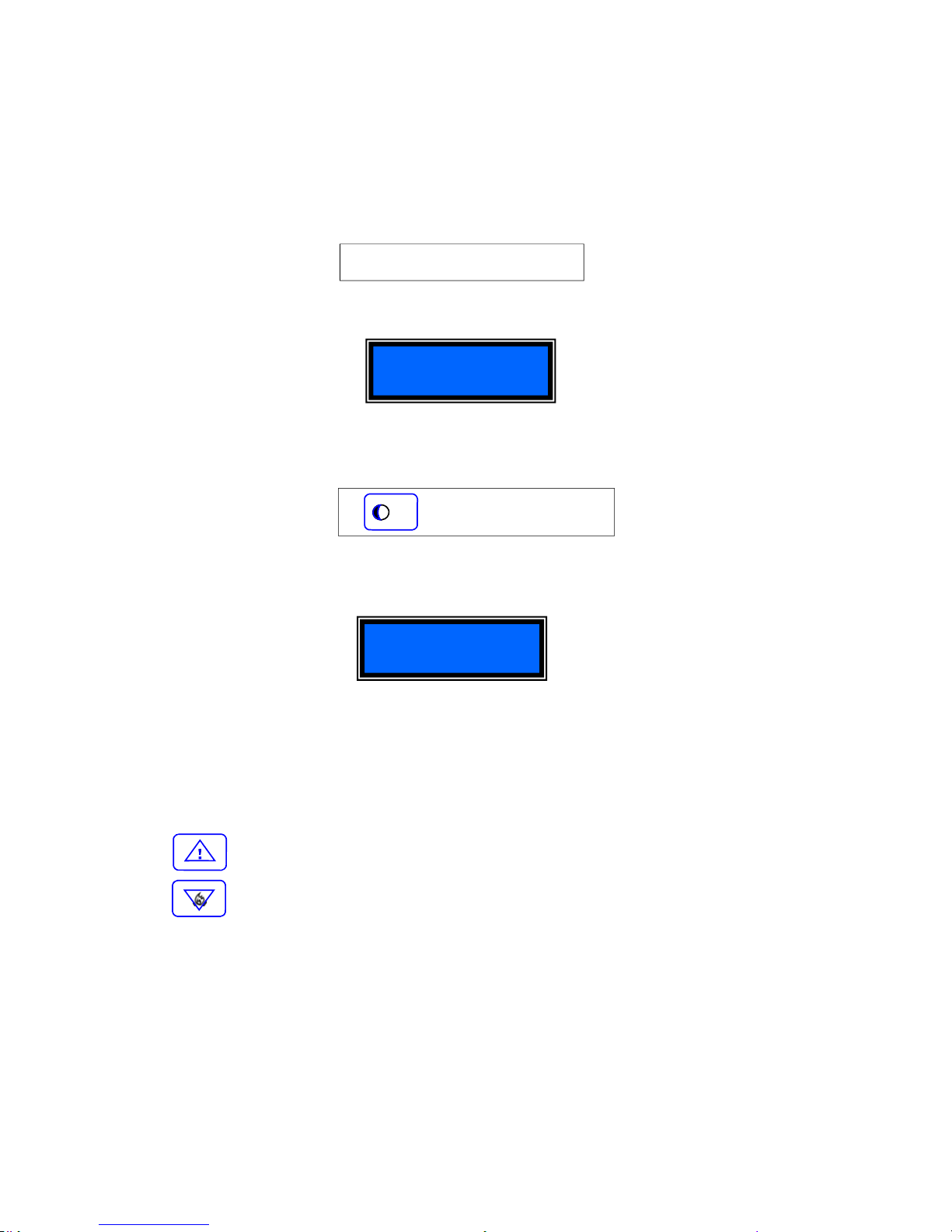
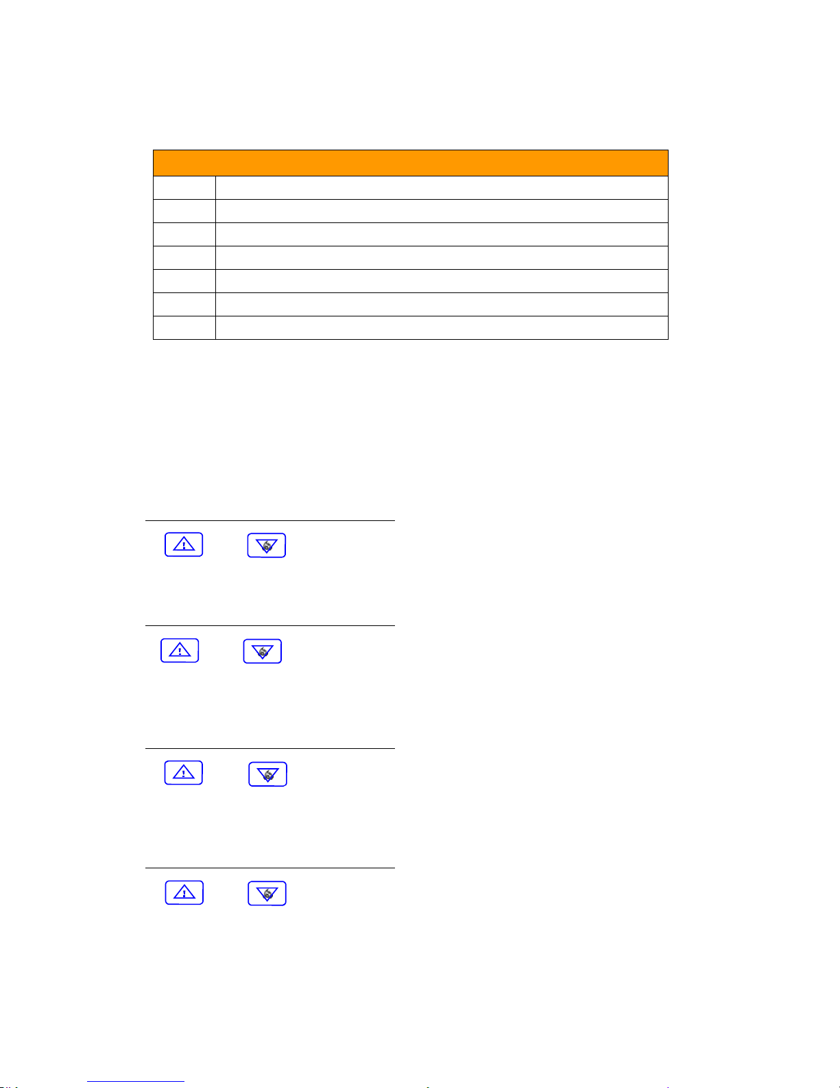
TO NAVIGATE WITH-IN THE MENU
The below keys are used to flow and navigate with-in the programming menu.
To exit the programming mode
When you are in the programming mode and you wish to exit, you must:
Press:
At this point, you will automatically exit the programming mode and return to stand-by mode.
Confirm
To return to an upper level of the menu
To proceed to the following page
To go back to the previous page
【 】+【 * 】+【#】
IN PROGRAMMING
#
F
F
Pag. 11 DUALCOM-8 INSTALLATION MANUAL
ENGLISH
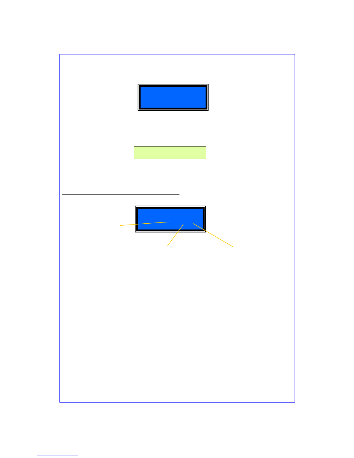
00. TO ENTER INTO PROGRAMMING MODE
Before entering into programming mode, be sure that the control panel is disarmed and that the LED
for “Areas 1 & 2” , “TAMPER”, “FIRE” e “ALARM 1 & 2” are all “OFF”. On the keypad KP-8R press
the buttons 012345 (this is the factory programmed installer code) and follow by (see blow:)
On the Display will appear:
01. Password Management
While in the programming mode press the keys:
On the display will appear:
Now you may program the following:
• The installer code.
• Security level code (up to 6)
• Operators password (up to 8).
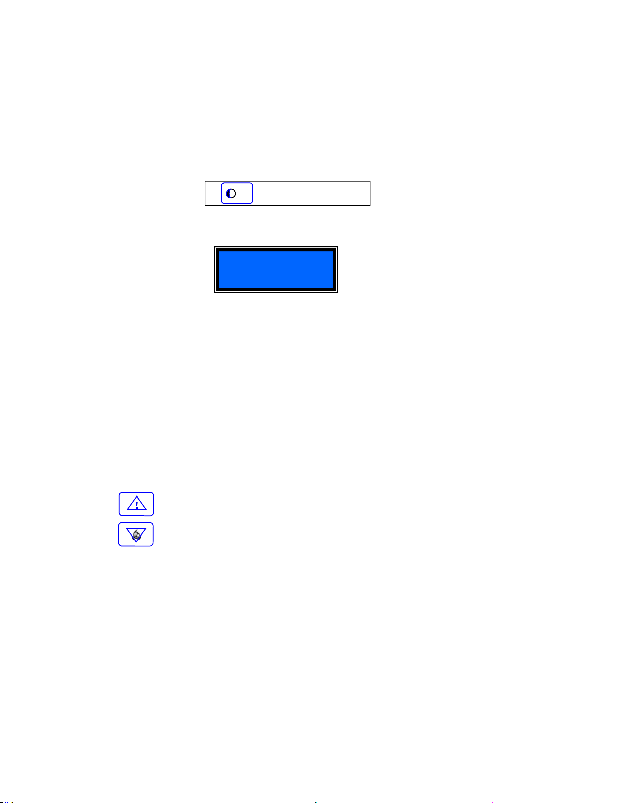
You may flow through the menu by pressing the keys:
To go to the next page.
To return to the previous page.
In alternative, you must press the code related to the programming address of submenu
Example
:
In the principle password management menu you my press【03】+【#】to program the
level of security and the password of the operator number 2.
PROGRAMMING
【012345】+【*】+【0】+【#】
【 】+【01】+【#】
Password
F
Pag. 12 DUALCOM-8 INSTALLATION MANUAL
ENGLISH
01.01 To change the existing password
In the principle menu of the password management, press the digits:
【01】+【#】on the display will
appear the factory Installed code:
To change the password, you must digit a number with 6 figures from 0 to 9, and then press【#】to
confirm. The keypad will emit a series of beeps.
The factory installed password is:
Example: If you wish to install a new code 654321; Press on the keypad (654321#)
01.02 Level of security and password of Operator 1
In the principal menu of the password management
, press the digits【02】+【#】on the display
will appear: Note: Operator 1 corresponds to 2, Operator 2 corresponds to 3 etc.
To change the security level and password of operator 1, you must press the keypad number th at
corresponds to the security level followed by the password of 4 figures and confirm with the key
【#】
The first number pressed will refers to the level of security desired. See below the levels available:
-0- Operator that has NO FUNCTION. (No function level)
-1- Operator can only DISARM the control panel.
-2- Operator can only ARM the control panel.
-3- Operator can only ARM and DISARM AREA 1
-4- Operator can only ARM and DISARM AREA 2
-5-
This Operator can operate all the functions of the control panel:
HE MAY
ARM OR DISARM, BY-PASS ZONES, ARM and DISARM ZONES BY-PASSED
EXAMPLE: If we want that the operator 1 be in level 4 with the password 1234; you must digit on the
keypad 41234#
0 1 2 3 4 5
Password
<01>012345
Password of 4 figures (in this case
0000 is factory installed).
Level of security is
5 (see 5 below)
This is the maximum security level.
Password
<02>50000
Operator
(in this case no.1)
Pag. 13 DUALCOM-8 INSTALLATION MANUAL
ENGLISH
01.03 Level of security and password of Operator 2
In the principle password management menu
, press the digits【03】+【#】and follow the description
in section 01.02 .
To change the security level and password of operator 2 you must press, on the keypad, the number
that corresponds to the level of security followed by a 4 digit password and confirm with the key
【#】.
The factory installed security level and password are:
• Level: 5
• Password : 0000
01.04 Security level and password of Operator 3
In the principle password management menu,
press the digits【04】+【#】and follow the description
in section 01.02 .
To change the security level and password of the operator 3 you must press, on the keypad, the
number that corresponds to the level of security followed by a 4 digit password and confirm with the
key【#】.
The factory installed security level and password are:
• Level: 5
• Password : 0000
01.05 Security level and password of Operator 4
In the principle password management menu,
press the digits【05】+【#】and follow the description
in section 01.02 .
To change the security level and password of the operator 4 you must press, on the keypad, the
number that corresponds to the level of security followed by a 4 digit password and confirm with the
key【#】.
The factory installed security level and password are:
• Level: 5
• Password : 0000
01.06 Security level and password of Operator 5
In the principle password management menu,
press the digits【06】+【#】and follow the description
in section 01.02 .
To change the security level and password of the operator 5 you must press, on the keypad, the
number that corresponds to the level of security followed by a 4 digit password and confirm with the
key【#】.
The factory installed security level and password are:
• Level: 5
• Password : 0000
5 0 0 0 0

Pag. 14 DUALCOM-8 INSTALLATION MANUAL
ENGLISH
01.07 Security level and password of Operator 6
In the principle password management menu,
press the digits【07】+【#】and follow the description
in section 01.02 .
To change the security level and password of the operator 6 you must press, on the keypad, the
number that corresponds to the level of security followed by a 4 digit password and confirm with the
key【#】.
The factory installed security level and password are:
• Level: 5
• Password : 0000
01.08 Security level and password of Operator 7
In the principle password management menu,
press the digits【08】+【#】and follow the description
in section 01.02 .
To change the security level and password of the operator 7 you must press, on the keypad, the
number that corresponds to the level of security followed by a 4 digit password and confirm with the
key【#】.
The factory installed security level and password are:
• Level: 5
• Password : 0000
01.09 Security level and password of Operator 8
In the principle password management menu,
press the digits【09】+【#】and follow the description
in section 01.02 .
To change the security level and password of the operator 8 you must press, on the keypad, the
number that corresponds to the level of security followed by a 4 digit password and confirm with the
key【#】.
The factory installed security level and password are:
• Level: 5
• Password : 0000
Pag. 15 DUALCOM-8 INSTALLATION MANUAL
ENGLISH
02.Telephone number management
To enter the telephone programming mode press the keys shown below:
On the display appears:
While in this mode, you may program:
• How the messages must be sent (7 methods);
• The telephone numbers to be memorized (up to 5);
• Select the Tel. Numbers which will manage the panels remote functions (up to 3)
You may flow up or down in the menu by pressing the keys:
To go to the next page.
To go to the previous page.
Example
:
While in the telephone management menu press the digits【03】+【#】to select how
you wish to send the 3rd number and program a new telephone number.
02.01 The first number for the alarm trigger transmission
In the principle telephone number management menu, press the
digits【01】+【#】on the
display will appear:
Enter the transmission method and the number with international code followed by 【#】
(maximum numbers digest that can be memorized are 16). The keypad does not have a “pause”
button and for this reason it may not be installed with a Telephone Exchange System.
Example:
Telephone
Telephone
<01>
Telephone
<01>4003934722000200
Telephone number that may be up to
maximum 16 digits with International
code included
Position
In this case the 1st
number memorized
Transmission method based on end user
needs. In this case 4: which is an SMS
message sent over the GSM network.
See table on page 16
【 】+【02】+【#】
F
Pag. 16 DUALCOM-8 INSTALLATION MANUAL
ENGLISH
Example
:
If we want assign to the number 003934722000200 the transmission method 4
• On the keypad press【01】+【#】to enter into programming mode.
• Immediately after press the number: 4003934722000200 #
Note: To enter an International code similar to +39 (this is the Italian code) the “+” must be
substituted with “00”, and you must enter (0039) followed by the telephone number.
02.02 2nd telephone number for the alarm trigger transmission.
In the principle telephone management menu,
press the digit【02】+【#】or flow Up / Down with:
【 】or【 】
Proceed by pressing the transmission method followed by the telephone number. Confirm with【#】
02.03 3rd telephone number for the alarm trigger transmission.
In the principle telephone management menu,
press the digit【03】+【#】or flow Up / Down.
【 】or【 】
Proceed by pressing the transmission method followed by the telephone number. Confirm with【#】.
02.04 4th telephone number for the alarm trigger transmission.
In the principle telephone management menu,
press the digit【04】+【#】or flow Up / Down.
【 】or【 】
Proceed by pressing the transmission method followed by the telephone number. Confirm with 【#】
02.05 5th number for the alarm trigger transmission.
In the principle telephone management menu,
press the digit【05】+【#】or flow Up / Down.
【 】or【 】
Proceed by pressing the transmission method followed by the telephone number. Confirm with【#】
0 Alarm trigger is sent through the PSTN network in form of voice message
1 Alarm trigger is sent through the PSTN network as ADEMCO 4+2 protocol
2 Alarm trigger is sent through the PSTN network as ADEMCO Contact ID protocol
3 Alarm trigger is sent through the GSM network in form of voice message
[4] Alarm trigger is sent through the GSM network in form of SMS
5 Alarm trigger is sent through the GSM network as ADEMCO 4+2 protocol
6 Alarm trigger is sent through the GSM network as ADEMCO Contact ID protocol
Transmission Method Description

Pag. 17 DUALCOM-8 INSTALLATION MANUAL
ENGLISH
02.06 1st telephone number used for the remote control of the Dualcom-8.
In this section you may memorize the telephone numbers that can be used for the remote management of the Dualcom-8 control panel. Follow the below sequence.
In the principle telephone number management menu
, press the digits【06】+【#】or move up and
down with the keys:
【 】or【 】
On the display will appear:
Proceed by entering the telephone number and confirm with the key 【#】.
Note: It is not necessary to insert the International dialling code.
Example
:
If we wish to insert in the transmission method 4 the number: +3934722000200
• Press digits 【06】+【#】, to enter the programming mode
• Immediately after press digits: 34722000200 #
02.07 To enter the 2nd remote management telephone number.
In the principle telephone management menu
, press digits【07】+【#】or go up and down with
keys:
【 】or【 】
Proceed by entering the 2nd telephone number and confirm with the key【#】.
Note: The international call code is not necessary.
02.08 To enter the 3rd remote management telephone number.
In the principle telephone management menu
, press digits【07】+【#】or go up and down with
keys:
【 】or【 】
Proceed by entering the 2nd telephone number and confirm with the key【#】.
Note: The international call code is not necessary.
Telephone
<06>
Phone
<06>34722000200
Pag. 18 DUALCOM-8 INSTALLATION MANUAL
ENGLISH
03. Management of the hardwire zones
In this section you will find how the hardwire zones must be managed.
Note: With the Dualcom-8 control panel, it is possible to have a minimum of 8 and a maximum of 24
hardwire zones by adding the expansion module EZ-8. With the on-board program, it is possible to
manage all 24 zones even if the EZ-8 expansion module is not installed by pressing the following
digits on the keypad. (see section A on page 62).
On the display appears:
In this mode the hardwire zones may be programmed with the following characteristics: Each number
below from 1 to 10 corresponds to a function. See design on page 19 section 03.01
1. Select alarm type (Burglary-Fire-Hold-up)
2. Zone with 24 hour trigger feature -(always armed)
3. Zone with immediate or delayed trigger
4. Type of siren (see design on section 03.01)
5. Type of sound emitted by the siren
6. Alarm trigger signal from keypad buzzer
7. Arming in DAY / NIGHT
8. Input RESPONSE TIME
9. Select contact trigger type (normally open or normally closed)
10. Select the area in which the zone must function. (Area 1 or Area 2)
You may flow through the menu by pressing the keys seen below:
To go to the previous page.
To go to the next page.
【 】+【03】+【#】
Wired Zone
F
Pag. 19 DUALCOM-8 INSTALLATION MANUAL
ENGLISH
03.01 Graphic design showing hardwire zone management
While in the menu for the hardwire zone management, press digits【01】+【#】or go up or down with:
【 】or 【 】
0 24 hour
[1]
Panel Armed
(2) ZONE TYPE
Wired zone
<01>5102000210
LIV Description Contact ID
0 Medical Distress Alarm 100
1 Fire Alarm 110
2 Gas Alarm 111
3 Panic Alarm 120
4 Hold-up Alarm 121
[5]
Burglary Alarm 130
6 Parametric Alarm 131
7 Flood Alarm 154
(1) TIPE OF ALARM
8 Pull Station 115
9 Tamper Alarm 144
[0]
Immediate
1 Delayed
(3) TIME
(4) TYPE OF OUTDOOR
SIREN
0 No Siren Installed
1 Hardwire Siren
[2]
Wireless Siren
3
Hardwire & Wireless
(5) TYPE OF SIREN SOUND
[0]
Burglary (continuous)
1 Hold-up (silent or sounding)
2 Fire (bell sound)
(6) KEYPAD BUZZER
[0]
NO Sound when Triggered
1 With Sound if Triggered
(7) DAY AND NIGHT MODES
[0]
Armed in Day mode
1 Armed in Night mode
(8) RESPONSE TIME
0 0-55 ms
1 1-250 ms
[2]
2-500 ms
3 3-750 ms
(9) TYPE OF CONTACT
0 Normally open
(1)
Normally closed
2 Line unbalanced*
(10) ASSOCIATATE TO
[0]
AREA 1
1 AREA 2
ZONE no.
** It is necessary to
insert the supplied 4k7
Ω resistor in series
with the sensor. By un
balancing this line an
alarm trigger will take
place

Pag. 20 DUALCOM-8 INSTALLATION MANUAL
ENGLISH
After having installed sensors in each zone and after making sure that this installation has been done
correctly, set the parameter of each zone and at the end press the【#】key to confirm. In case of
doubts, it is best to repeat the programming sequence rather than risk malfunction of the panel.
Example of zone parameter settings:
Zone 1 must be set for:
1. (5) Burglary Alarm
2. (1) Zone is controlled by Arm/Disarm
3. (0) Zone is immediate
4. (2) Outdoor wireless siren is active
5. (1) Siren sound is continuous
6. (1) Keypad alarm buzzer is in function
7. (1) Panel set for night mode
8. (2) Alarm response time set for 500 mille seconds
9. (1) Alarm trigger set for normally closed contacts
10. (0) Alarm set for the Area 1 trigger only
Setting on the display must be as shown below:
After setting is terminated press【#】to confirm.
03.02 Setting of the 2nd. to the 24th hardwire zone follow the procedure below:
In the menu for the management of the hardwire zones
, press the digits:
【(02-24)】 +【#】
or go up and down with the keys:
【 】or【 】
Follow the setting indications shown in section 03.01.
Carefully digit on keypad the programming sequence and at the end press the【#】key to confirm.
Wired zone
<01>5102111210

Pag. 21 DUALCOM-8 INSTALLATION MANUAL
ENGLISH
04. Management of the wireless zones
In this section it is possible to manage and set 48 wireless zones.
To memorize and set, on the keypad, press the keys seen below:
On the display will appear :
In this mode you may program all wireless zone to function as shown below:
1. Select alarm type (Burglary - Fire - Hold-up)
2. Zone must function 24 hours or only when panel is Armed
3. Zone must be immediate or delayed
4. Type of siren it must trigger (Hardwire or Wireless)
5. Type of sound the siren must emit
6. Setting of keypad buzzer
7. Arming in mode DAY or NIGHT
8. Sensor battery control function
9. Wireless sensor to be set for protection of Area 1 or Area 2
You may go up and down in the menu by pressing:
To go to the next page.
To go to the previous page.
IMPORTANT NOTICE:
This section indicates only how the wireless zones must function. All sensors are manufactured with
the “PEGASO” wireless transmission protocol and must be self learned by the control panel. See
section 10.02 to understand how this must be done.
The management of all wireless sensor begin with zone 25 up to zone 72.
【 】+【04】+【#】
Wireless zones
F

Pag. 22 DUALCOM-8 INSTALLATION MANUAL
ENGLISH
04.01 Management and settings of wireless zone that start from zone 25 and end with zone 72.
In the menu for the management of the wireless zones, press the digits【25】+【#】or move up and
down with the keys:
【 】or 【 】
On the display will appear:
0 24 h
[1]
Armed Panel
(2) TIPO ZONA
Wireless zone
<25>510111100
LIV Description Contact ID
0 Medical distress Alarm 100
1 Fire Alarm 110
2 Gas Alarm 111
3 Panic Alarm 120
4 Hold-up Alarm 121
[5]
Burglary Alarm 130
6 Parametric Alarm 131
7 Flood Alarm 154
(1) TYPE OF ALARM
8 Pull Station 115
9 Tamper Alarm 144
(7) DAY AND NIGHT MODES
0 Armed in Day mode
[1]
Armed in Night mode
(8) SENSOR LOW BATTERY
TRANSMITTION
[0]
Not in function
1 In function
(9) ASSOCIATED TO
AREA
[0]
Area 1
1 Area 2
ZONE no.
[0]
Immediate
1 Delayed
(3) TIME
(4) TYPE OF OUTDOOR
SIREN
0 No Siren Installed
[1]
Hardwire Siren
2 Wireless Siren
3 Hardwire & Wireless
(5) TYPE OF SIREN SOUND
[1]
Burglary (continuous)
2 Hold-up (silent or sounding)
3 Fire (bell sound)
(6) KEYPAD BUZZER
0 NO Sound when Triggered
[1]
With Sound if Triggered

Pag. 23 DUALCOM-8 INSTALLATION MANUAL
ENGLISH
After having installed sensors in each zone and after making sure that this installation has been done
correctly, set the parameters of each zone and at the end press the【#】key to confirm. In case of
doubts, it is best to repeat the programming sequence rather than risk malfunction of the panel.
Example of wireless zone settings:
Zone 25 must be sent for:
1. (5) Burglary Alarm
2. (1) Zone must be controller by Arm/Disarm
3. (0) Zone must be immediate
4. (1) Outdoor Hardwired siren armed
5. (1) Type of siren alarm sound
6. (1) Keypad pre-alarm buzzer in function
7. (1) Panel set for night mode
8. (0) No signal from panel of low battery sensor
9. (0) Alarm set for the Area 1 trigger only
Setting on the display must be as shown below:
After setting is terminated press【#】to confirm.
04.02 Setting of wireless zone 26 to 72 follow procedure below:
In the menu for the management of the hardwire zones
, press the digits:
【(26-72)】 +【#】
Go up and down with the keys:
【 】or【 】
Follow the setting indications shown in section 04.01.
Carefully digit on keypad the programming sequence and at the end press the【#】key to confirm.
Wireless zone
<25>510111100

Pag. 24 DUALCOM-8 INSTALLATION MANUAL
ENGLISH
05 Management of the hardwire zones for alarm transmission to the
memorized telephone numbers.
In this section we associate the alarm transmission of the hardwire zones to the memorized
telephone numbers.
Note: With the on-board program you may manage all the 24 possible hardwire zones even if the
expansion board EZ-8 is not installed.
This is how it must be done. Press on the keypad the below keys:
On the Display appears:
All zones may be programmed to transmit the alarm trigger message:
1. To the 1st telephone number memorized
2. To the 2nd telephone number memorized
3. To the 3rd telephone number memorized
4. To the 4th telephone number memorized
5. To the 5th telephone number memorized
You may select the correct menu by pressing the UP and DOWN keys seen below:
To go back to the next page.
To go to the previous page.
【 】+【05】+【#】
Wired report
F

Pag. 25 DUALCOM-8 INSTALLATION MANUAL
ENGLISH
05.01 Management of zone 1 for the alarm trigger transmission
In the menu for the management of the zone alarm transmission,
press the digits【01】+【#】 or
flow up and down in the menu with the keys: 【 】or 【 】
On the Display appears:
After you are sure that all the alarm transmission function are okay, set the parameters and press th e
key【#】to confirm. In case of doubt it is best to repeat the control panel sequence rather then
risk panel malfunction.
Example of how to program:
Zone 1 must be programmed as follows:
1. (1) Transmit the alarm to the first telephone number
2. (1) Transmit the alarm to the second telephone number
3. (1) Transmit the alarm to the third telephone number
4. (0) No alarm transmission to the fourth telephone number
5. (1) Transmit the alarm to the fifth telephone number
On the Display appears:
To confirm press the key【#】.
05.02-24 Management of the remaining zones 2 to 24 for the telephone alarm transmission
Proceed with the programming as indicated in section 05.01. You must enter into programming
mode by pressing the keys:【(02-24) 】+【#】or flow with up/down with the keys 【 】or
【 】
Wired report
<01>11101
TRANSMISSION OF THE ALARM TO:
(1)
First number
0=no transmission
[1] = transmit
(2)
Second number
0=no transmission
[1] = transmit
(3)
Third number
0=no transmission
[1] = transmit
(4)
Forth number
[0] = no transmission
1=transmit
(5)
Fifth number
0=no transmission
[1] = transmit
ZONE no.
Wired report
<01>11101

Pag. 26 DUALCOM-8 INSTALLATION MANUAL
ENGLISH
06
Management of the wireless zones for the alarm transmission to the
memorized telephone numbers
In this section you may learn how to program the wireless zones for the telephone alarm
transmission.
To memorise press the following digits on the keypad:
On the display will appear:
Now you may program the alarm transmission as shown below:
1. To the 1st tel. Number memorized
2. To the 2nd tel. Number memorized
3. To the 3rd tel. Number memorized
4. To the 4th tel. Number memorized
5. To the 5th tel. Number memorized
You may select the correct menu by pressing the UP and DOWN keys seen below:
To go back to the next page.
To go to the previous page.
【 】+【06】+【#】
Wireless report
F

Pag. 27 DUALCOM-8 INSTALLATION MANUAL
ENGLISH
06.01 Management of the wireless zones for tel. Alarm transmission
NOTE: The wireless zone tel. Transmission is form zone 25 to 72.
When in the tel. Alarm transmission menu
, press the digits【25】+【#】or flow up and down in the
menu with the keys: 【 】or 【 】
On the display will appear:
Set the parameters for the telephone alarm transmissions and at the end confirm with the【#】.
Example of a typical setting:
Setting of zone 25 :
1. Transmission of the alarm to the 1st. tel. Number memorized for this zone.
2. NO transmission of the alarm to the 2nd. Number memorized.
3. NO transmission of the alarm to the 3rd. Number memorized.
4. NO transmission of the alarm to the 4th number memorized.
5. Transmission of the alarm to the 5th number memorized.
Press the following keys:
At the end, confirm with the 【#】.
06.02-24 Management of the zones 26 to 72 for the wireless tel. Alarm transmission.
Proceed as described in section 06.01. You must, however, enter into the programming mode by:
Pressing the digits【(26-72) 】+【#】or flow up and down in the menu with the keys: 【 】or
【 】
Wireless report
<25>10001
TRANSMISSION OF THE ALARM TO:
(1)
First number
0=no transmission
[1] = transmission
(2)
Second number
[0] = no transmission
1 = transmission
(3)
Third number
[0] = no transmission
1 = transmission
(4)
Forth number
[0] = no transmission
1=transmission
(5)
Fifth number
0=no transmission
[1] = transmission
ZONE no.
Wireless report
<25>10001

Pag. 28 DUALCOM-8 INSTALLATION MANUAL
ENGLISH
07 Management of event report transmissions to memorized tel. numbers
In this section you will find the management of the control panel events (Faults, Relay Status, Access
etc. …) and how they may be transmitted to the memorized dialler telephone numbers.
To memorize a new number press the keys:
On the display appear:
In this section, each zone may be programmed to transmit the event reports
1. To the first telephone number
2. To the second telephone number
3. To the third telephone number
4. To the fourth telephone number
5. To the fifth telephone number
You may select the correct menu by pressing the UP and DOWN keys seen below:
To go back to the next page.
To go to the previous page.
REPORT SCHEDULE
【 】+【07】+【#】
Other report
* REPORT NUMBER INFORMATION REPORTED
01 GSM NESTWORK FAULT
02 PSTN NETWORK FAULT
03 CONTROL PANEL BATTERY LOW
04 MAINS FALURE 230 Vac
05 PANEL ARM / DISARM
06 RELAY 1 STATUS
07 RELAY 2 STATUS
08 RELAY 3 STATUS
09 EMERGENCY OR MEDICAL DISTRESS
10 FIRE ALARM TRIGGER
11 HOLD-UP ALARM TRIGGERED
12 EXIT OF PROGRAMMING MODE
13 TEST OF REPORTS
14 WIRELESS SENSOR LOW BATTERY REPORT
15 ZONE BY-PASSED REPORT
F

Pag. 29 DUALCOM-8 INSTALLATION MANUAL
ENGLISH
07.01
Sending SMS message to report problem (01) see report table on page 28 (GSM LINE
FAULURE )
In the menu for the SMS report transmission of
, press the digits【01】+【#】or flow up and down in
the menu with the keys: 【 】or 【 】
On the display appears:
Set all the parameters for the report transmissions, and at the end press the key【#】to confirm.
Be sure to check all setting to avoid malfunction of the control panel.
Programming example :
REPORT for 01 must be set:
1. (1) Transmission to the first telephone number
2. (0) NO transmission to the second telephone number
3. (0) NO transmission to the third telephone number
4. (0) NO transmission to the fourth telephone number
5 (1) Transmission to the fifth telephone number
After having set the REPORT parameters press【#】to confirm.
07.02-24 To set the 2nd to the 15th REPORT to transmit by SMS message.
Proceed as described in section 07.01 by pressing the report number first as shown below:
Press digits 【(02 to 25) 】+【#】 or flow up and down in the menu with the keys: 【 】or
【 】
Then proceed as described in section 07.01.
Other report
<01>10001
REPORT SMS TRANSMISSION
(1)
First number
0 = no tranmission
[1] = transmission
(2)
Second number
[0] =no transmission
1 = transmission
(3)
Third number
[0] =no transmission
1 = transmission
(4)
Forth number
[0] =no transmission
1= transmission
(5)
Fifth number
0=no transmission
[1] = transmission
REPORT no.
Other report
<01>10001
Assigned number*
(Table Report)

Pag. 30 DUALCOM-8 INSTALLATION MANUAL
ENGLISH
08
CONTROL MONITORING STATION setting and management ( CMS):
In this section is described how to create and account and manage a CMS alarm trigger using the
ADEMCO 4+2 and CONTACT ID protocols.
To memorize press on the keypad the following keys:
On the Display you will see:
In this section you may:
1. Program an account using the “ADEMCO 4+2” Protocol
2. Program an account to be managed the Protocol “CONTACT ID”
You may select the correct menu by pressing the UP and DOWN keys seen below:
To go back to the next page.
To go to the previous page.
【 】+【08】+【#】
Account
F

Pag. 31 DUALCOM-8 INSTALLATION MANUAL
ENGLISH
08.01 Account management with protocol ADEMCO 4+2 (see 08)
In the CMS management menu
, press the digits【01】+【#】or flow up and down in the menu with
the keys: 【 】or 【 】
On the Display will appear:
Insert the number of four figures given to the end user by the CMS (control monitoring station) to
connect and identify the control panel and at the end press【#】to confirm.
Programming example:
To create an account with the number assigned:
1. 1111
Digit this number and at the end confirm with the 【#】. On the Display you will see:
08.02 To program an account using the ADEMCO 4+2 protocol and managed by CONTACT ID
In the CMS management menu
, press the digits【01】+【#】or flow up and down in the menu with
the keys: 【 】or 【 】
On the Display will appear:
Insert the number assigned by the CMS to identify the control panel connected and at the end
confirm with 【#】. Example: To open an account with the number 2222, press this number on your
keypad and the Display will show:
At the end press【#】to confirm.
Account
<01> 1111
Account
<01> 1111
Account
<02> 2222
Account
<01> 2222

Pag. 32 DUALCOM-8 INSTALLATION MANUAL
ENGLISH
CODE IDENTIFICATION TABLE FOR THE ADEMCO Contact ID PROTOCOL
Alarm Event ADEMCO Contact
ID code
Medical Distress 100
Fire Alarm 110
Gas Alarm 111
Panic Alarm 120
Hold-up Alarm 121
Burglary Alarm 130
Perimetrical Alarm 131
Flood Alarm 154
Pull Station 115
Tamper Alarm 144

Pag. 33 DUALCOM-8 INSTALLATION MANUAL
ENGLISH
09 SMS Message Management.
In this section you can under stand how to write or cancel an SMS message.
To write and memorize a new message, press the digits seen below:
On the Display will appear:
You may now memorize:
1. A new SMS message
2. Cancel an old SMS message
You may select the correct menu by pressing the UP and DOWN keys seen below:
To go back to the next page.
To go to the previous page.
09.01 To memorize a new SMS message
In the menu for SMS Alarm Trigger message transmission
, press the digits【01】+【#】or flow up
and down in the menu with the keys: 【 】or 【 】
On the display appears: This indicates that Dualcom-8 is ready to memorize the 1st. SMS message.
To continue proceed as follows:
∗ On your portable telephone prepare the text messa ge you wish to memorize in the Dualcom
WITHOUT SENDING IT
∗ On the keypad press the Digits 【01】+【#】to memorize the first SMS message, which in
this case is “Arm Area1”
∗ From your portable phone send to the Dualcom-8 SIM card the prepared message.
∗ The Dualcom-8 will emit a series of beeps to confirm that the message has been received.
and on the Display will appear :
【 】+【09】+【#】
Sms
Sms
<01>01
Sms
<01>02
F

Pag. 34 DUALCOM-8 INSTALLATION MANUAL
ENGLISH
NOTE: The below messages are factory installed but can be cancelled and new messages
can be installed. In this operation indicate first the message position followed by the new
SMS.
09.02 SMS message management: To cancel a message
Whole in the SMS transmission menu
, press the digits【02】+【#】or flow up and down in the menu
with the keys: 【 】or 【 】
On the Display will appear:
NOTE: THE MESSAGES SHOWN IN THE ABOVE TABLE 01 TO 08 ARE FTY. INSTALLED
When you install a new SMS message the fty. installed message, will automatically over ride the
factory installed message. If you then cancel the newly installed message, the factory installed message will be again installed. To cancel a newly installed message, you must press the digits for【(02
to 08)】+【#】and follow the indications in the above table.
Position Factory Installed Message
01
SMS Text message : max. 120 characters Relay 1 “ON”
02
SMS Text message : max. 120 characters Relay 2 “ON”
03
SMS Text message : max. 120 characters Relay 3 “ON”
04
SMS Text message : max. 120 characters Relay 1 “OFF”
05
SMS Text message : max. 120 characters Relay 2 “OFF”
06
SMS Text message : max. 120 characters Relay 3 “OFF”
07
SMS Text message : max. 120 characters HELP CALL
08
SMS Text message : max. 120 characters OTHER EVENT
Sms
<02>01
Sms
<01>01
Position

Pag. 35 DUALCOM-8 INSTALLATION MANUAL
ENGLISH
10 Self learning of wireless sensor and keychain transmitters
In this section is described how you may memorize in the Dualcom-8 panel the “Pegaso” protocol
sensors. Inside of the K-8R keypad, supplied with the DUALCOM-8, is a specially made
TRANSCEIVER capable of receiving alarm trigger messages from all wireless sensors and keychain
transmitters and re-transmit these signals to the installed “Pegaso” sirens.
It is important to install this keypad in a position centrally located between all sensors in order to
increase the reception range of the R.F. transmissions.
To enter in this programming mode press the digits seen below:
On the Display will appear:
When in code learning mode you may:
1. Learn the codes of the Keychain transmitters
2. Learn the codes of all Sensor
3. Program the wireless sirens with the Dualcom-8
4. Learn and manage the remote electronic keys
10.01 To have the Dualcom-8 self learn the Peg-3 keychain transmitter
NOTE: The keychain transmitters and the electronic keys are programmed and combined with
an operator that has also a security level.
Example: By memorizing a keychain transmitter in the first position, it is automatically associated with
the operator 1 which may be then associated from level 0 to level 5 of security. If it is associated with,
for example, level 4, then the operator 1 can only Arm or Disarm the AREA number 2.
(See table on Page 12)
【 】+【10】+【#】
Code learning
1° Keychain trans. Operator 1 1st Key
2° Keychain trans. Operator 2 2nd Key
3° Keychain trans. Operator 3 3rd Key
4° Keychain trans. Operator 4 4th Key
5° Keychain trans. Operator 5 5th Key
6° Keychain trans. Operator 6 6th Key
7° Keychain trans. Operator 7 7th Key
8° Keychain trans. Operator 8 8th Key
Keychain TX Operator Electronic Key Security Level
Level [0 to 5]
Level [0 to 5]
Level [0 to 5]
Level [0 to 5]
Level [0 to 5]
Level [0 to 5]
Level [0 to 5]
Level [0 to 5]
F

Pag. 36 DUALCOM-8 INSTALLATION MANUAL
ENGLISH
In the wireless sensor and electronic key self learning menu, press the digits 【01】+【#】or flow up
and down in the menu with the keys: 【 】or 【 】
On the Display will appear:
To have the Dualcome-8 self learn the first keychain Tx, press: 【01】+【#】
The Display will show:
The keypad will sound 2 beeps. At this point you must press the upper right hand button on the
Keychain Tx. The keypad will emit a series of beeps to confirm that the code has been received and
learned by the Dualcom-8. Soon after the Display will confirm this by showing:
To self learn another keychain Tx press 【(02-08) 】+【#】
The Display will show:
The keypad will sound 2 beeps. Press the n°1 button on the upper left hand of the keychain Tx.
(see appendix C on Page 63); The keypad will emit a series of beeps to confirm that the code has
been received and learned.
If a keychain Tx has already been learned the Display will show:
Code learning
<01>
Code learning
<01>01
Code learning
<01>02
Code learning
<01>02
02-08:
Position number
Code learning
<01>02F53680CD
“Pegaso” code learned
(in this case F53680CD)
Keychain Tx position
(in this case 2)

Pag. 37 DUALCOM-8 INSTALLATION MANUAL
ENGLISH
10.02 How you must self learning the wireless sensors.
In the self learning menu for sensors, keychain Tx. and Electronic Keys,
Press the digits 【02】+
【#】 or flow up and down in the menu with the keys: 【 】or 【 】
The Display will show:
Note: The self learning wireless zones start with 25 and go up to 72.
To have the control panel self learn a wireless sensor, press the digits: 【(25 –72) 】+【#】
On the Display will show:
The keypad will emit 2 beeps. At this point you must have the sensor send an alarm trigger transmission. The keypad will emit a series of beeps to confirm that the transmission has been received and
the code has been learned. Soon after the Display will show:
To have other sensors learned you must proceed by pressing the digits 【(26-72) 】+【#】
On the Display will show:
If a sensor has been already learned on the Display you will see:
Code learning
<02>
Code learning
<02>25
Code learning
<02>26
Code learning
<02>26
25-72:
Position No. or (Zone)
Code learning
<02>2522AD3304
“Pegaso” code learned
(in this case 22AD3304)
Sensor Position or Zone
(in this case zone 25)

Pag. 38 DUALCOM-8 INSTALLATION MANUAL
ENGLISH
10.03 How to cancel the Keychain Tx. from the Dualcom-8 memory
In the self learning menu for the Sensors, Keychain Tx. and Electronic Key
press the digits:
【03】+【#】 or flow up and down in the menu with the keys: 【 】or 【 】
The Display will show:
To cancel the first Keychain Tx., press: 【01】+【#】
The Display will show:
The keypad will emit 2 beeps to confirm that the code previously learned has been cancelled.
To cancel the next Keychain Tx. press: 【(02-08) 】+【#】
The Display will show:
The keypad will emit 2 beeps to confirm that the code previously learned
has been cancelled.
Code learning
<03>01
Code learning
<03>01
Code learning
<03>02
02-08:
Position number

Pag. 39 DUALCOM-8 INSTALLATION MANUAL
ENGLISH
10.04 How to cancel the wireless sensor from the Dualcom-8 memory
In the menu to self learn the Sensor, Keychain Tx. and Electronic Keys,
press the digits
【04】+【#】 or flow up and down in the menu with the keys: 【 】or 【 】
The Display will show:
To cancel the sensor that has been self learned on Zone 25, Press the digits: 【25】+【#】
On the Display you will see:
The keypad will emit 2 beeps to confirm that the zone 25 sensor has been deleted for the memory.
To cancel any other wireless sensor memorize in any of the zones, press digits : 【(26-72) 】+
【#】
On the Display you will see:
The Keypad will emit 2 beeps to confirm that the sensor previously learned
had been deleted form the memory.
10.05 Self learn of “Pegaso” wireless outdoor siren
To memorize a siren with the Dualcom-8, it is necessary that the siren be set to receive a
“Pegaso” code transmission form the control panel. To set the siren dip switch, read the siren
installation instructions.
In the menu for the self learning of the Sensor, Keychain Tx. and Electronic Keys,
press the digits:
【05】+【#】or flow up and down in the menu with the keys: 【 】or 【 】
On the Display you will see:
When the Dualcom-8 is in this mode, it will automatically transmit to the siren it’s code and the siren
will self learn this code. To repeat this function you must press the digits【05】+【#】or flow up and
down in the menu with the keys: 【 】or 【 】
Code learning
<04>25
Code learning
<04>25
Code learning
<04>26
26-72:
Position or Zone No.
Code learning
<05>12345678
12345678: Pegaso
Transmission code
sent to siren

Pag. 40 DUALCOM-8 INSTALLATION MANUAL
ENGLISH
10.06 How to have the Dualcom-8 self learn an Electronic Key SK-8.
In the menu for the self learning of the Sensor, Keychain Tx. and the Electronic Keys,
you must press
the digits 【06】+【#】or flow up and down in the menu with the keys: 【 】or 【 】
On the Display will appear:
To self learn the 1st electronic key, press digits: 【(01 ) 】+【#】
On the Display will appear:
The keypad will emit 2 beeps. At this point you must insert the SK-8 key into is receptacle SK-8B.
The Dualcom - 8 keypad will emit a series of beeps to confirm that it has accepted the key code and
is ready to function. Immediately after the display will show the number for the next key to be learned.
To self learn another Electronic Key press the digits 【(02-08) 】+【#】
On the Display will appear:
If a key has already been self learned, on the display will appear:
Code learning
<06>
Code learning
<06>01
Code learning
<06>02
Code learning
<06>02
02-08:
Position number
Code learning
<06>0244EE0225
The self learned “Pegaso”
Code (in this case is
( 44EE0225)
Key Position
(in this case 02)

Pag. 41 DUALCOM-8 INSTALLATION MANUAL
ENGLISH
11 Management of the Voice Messages
This section will describe how to memorize the voice message used in the alarm trigger telephone
transmissions. Up to 8 different messages may be memorized.
Note: the Dualcom-8 must be set to receive the messages. See section XXX.
In the programming menu press the digits:
On the Display will appear:
In this mode we can:
1. Record the voice messages
2. Listen to the playback of the voice messages
In the below table we see 8 positions. Each position corresponds to a message which must be
memorized for the use indicated in the table:
11.01 Recording of the voce messages
In the menu for the management of the voice messages.
press the digits 【01】+【#】or flow up
and down in the menu with the keys: 【 】or 【 】
On the Display will appear:
【 】+【11】+【#】
Voice
Position Message Associated to
01 Duration: 8 seconds Area 1 Armed
02 Duration: 8 seconds Area 1 Disarmed
03 Duration: 8 seconds Area 2 Armed
04 Duration: 8 seconds Area 2 Disarmed
05 Duration: 8 seconds Area 1 Triggered
06 Duration: 8 seconds Area 2 Triggered
07 Duration: 8 seconds Request for HELP
08 Duration: 8 seconds Other Event
Voice
<01>01
F

Pag. 42 DUALCOM-8 INSTALLATION MANUAL
ENGLISH
TO START:
The microphone for message recording is found on position 49 of the mother board (see page 4).
Before recording be sure that there is no back ground noise and that you speak clearly, slowly and
as close as possible to the microphone. The playback speaker is supplied separately with the control
panel and is inserted in the position 50 (see page 4) RECORDING TIME IS 8 SECONDS.
To record the first message press the digits: 【(01 ) 】+【#】
On the Display will appear:
Proceed immediately to record the 1st. voice message and at the end, on the Display will appear:
This indicates that the 1st. Message has been recorded and that the Dualcom-8 is ready for the 2nd
voce message. To record the 2nd to 8th message, press the digits: 【(02-08 ) 】+【#】
On the Display appears:
Proceed immediately to record the 2nd. voice message and at the end, on the Display will appear:
This indicates that the 2nd. message has been successfully recorded and that the Dualcom-8 is
ready for the 3rd message.
To hear the playback of the 1st recorded message you must plug-in the loud speaker into
position 50 on page 4. Press the digits: 【(02 ) 】+【#】
On the Display appears:
You may listen to all 8 messages recorded by pressing the keys【(02-08 ) 】+【#】or flow up and
down in the menu with the keys: 【 】or 【 】
Voice
<01>01
Voice
<01>02
Voice
<01>02
01 to 08: Number of the
message recorded
Voice
<01>03
01 to 08:
Number of the
message recorded
Voice
<02>01

Pag. 43 DUALCOM-8 INSTALLATION MANUAL
ENGLISH
On the Display appears:
Through the loud speaker plugged into the mother board (see page 4), you will hear the recording
playback.
12 Additional settings
In this section you will see how to set other important parameters for the Dualcom-8 control panel.
While in the programming menu press the digits:
On the Display appears:
In this mode you may set the following:
1. Set the number of rings for the remote interrogation.
2. Priority between the PSTN or GSM network.
3. Set the format for the GSM alarm trigger transmission.
4. Set the number of transmission attempts that must take place in case of tel. line fault.
5. Able or Disable the keypad or PC. connection to program the Dualcom-8.
6. Able or Disable the keypad tone that indicates PSTN and GSM line failure.
7. Set the Dualcom-8 to Arm even if there are Zones not in function.
8. Set the Entrance and Exit delay times.
9. Set the siren and keypad alarm trigger time.
10. Set the date and the hour.
11. Set the synchronism of the events.
Voice
<02>01
01 to 08:
Message recording number
【 】+【12】+【#】
Other setting
F

Pag. 44 DUALCOM-8 INSTALLATION MANUAL
ENGLISH
12.01 How to set the number of rings for the remote interrogation.
In the menu “other setting”
press the digits 【01】+【#】or flow up and down in the menu with the
keys: 【 】or 【 】
On the Display appears:
To change these parmeters, press the digits: 【(01 ) 】+【#】
On the Display appears:
Press, on the keypad, the desired parameters to be
set and at the end confirm with【#】.
The keypad will emit 2 beeps as confirmation of setting.
12.02 Priority of selection between the PSTN and GSM network
In the menu “other setting”
press the digits 【02】+【#】 or flow up and down in the menu with the
keys: 【 】or 【 】
On the Display appears:
To change these parameters press the digit: 【(02 ) 】+【#】
On the Display appears:
Other setting
<01>42
GSM telephone dialler settings
[1-9] Number of rings for alarm trigger (in this case 2)
[0] GSM remote management is not active.
Other setting
<01>42
PSTN telephone dialler settings
[1-9] number of rings for alarm to trigger (In this case 4)
[0] PSTN remote management is not active.
Other setting
<02>201
Number of telephone line attempts before
network change
[1-9] Number of attempts (in this case [1])
Other setting
<02>201
Change method between networks
[0] Automatic change in case of network failure.
[1] Normal change, in case of network failure, automatic
change after a defined number of transmission attempts.
Mode
[0] PSTN and GSM networks working together: In case
one fails the other network will pick up the transmission.
[1] PSTN network priority: If this network is not working
the transmission will automatically be sent by GSM.
[2] GSM network priority: If this network is not working the
transmission will be automatic sent by PSTN.

Pag. 45 DUALCOM-8 INSTALLATION MANUAL
ENGLISH
At this point with the keypad enter the desired parameters and at the end, to confirm press【#】
2 beeps will be emitted by the keypad as confirmation.
12.03 Setting the GSM dialler for the transmission to the Control Monitoring Station (CMS)
In the menu “Other settings”
press the digits 【03】+【#】or flow up and down in the menu with the
keys: 【 】or 【 】
On the Display appears:
To change these parameters press the digits: 【(03 ) 】+【#】
On the Display appears:
At this point, on your keypad select the desired parameter and confirm with the key【#】.
The keypad will emit 2 beeps to confirm.
12.04 To set the number of time a message must be sent to each memorized tel. number.
In the menu “Other setting” press the
digits 【04】+【#】or flow up and down in the menu with the
keys: 【 】or 【 】
On the Display appears:
To change these parameters press the digits: 【(04 ) 】+【#】
On the Display appears:
At this point, on the keypad, select the desired parameters and confirm with the key 【#】
The keypad will emit 2 beeps to confirm.
Other setting
<03>0
Format GSM
[0] Ordinary format
Other setting <03>0
Other setting
<04>1
Number of call attempts
[0] For ever
[1-9] Minimum 1 - Maximum 9 Attempts.
Other setting
<04>1

Pag. 46 DUALCOM-8 INSTALLATION MANUAL
ENGLISH
12.05 How to enable a Keypad or Computer so it may be used to programming the Dualcom-8
In the menu “Other setting”
press the digits 【05】+【#】or flow up and down in the menu with the
keys: 【 】or 【 】
On the display will appear:
To change these parameters press : 【(05 ) 】+【#】
On the Display appears:
On the keypad digit the desired parameters and confirm with the key 【#】
The keypad will confirm with 2 beeps.
12.06 Audio and visual signals form the Keypad in case of PSTN or GSM network failure
In the menu “Other setting”
press the digits 【06】+【#】 or flow up and down in the menu with the
keys: 【 】or 【 】
On the Display appears:
To change these parameters press the digits: 【(06 ) 】+【#】
On the Display appears:
On the keypad digit the desired parameters and confirm with the key 【#】
The Keypad will confirm with 2 beeps.
Other setting
<05>11
Enable PC programming through USB port
[0] Not Enabled
[1] Enabled
Other setting
<05>11
Enable Keypad for programming
[0] Not Enabled
[1] Enabled
Other setting
<06>11
In case of GSM network failure
[0] Not Enabled
[1] Enabled
Other setting
<06>11
In case of PSTN network failure
[0] Not Enabled
[1] Enabled

Pag. 47 DUALCOM-8 INSTALLATION MANUAL
ENGLISH
12.07 Setting the Dualcom-8 procedure in case of Faulty or Inactive Zone
In the menu “other setting”
press the digits 【07】+【#】 or flow up and down in the menu with the
keys: 【 】or 【 】
On the display will appear:
To change these parameters press the digits: 【(07 ) 】+【#】
On the Display appears:
On the keypad, digit the desired parameters and confirm with the key 【#】
The Keypad will confirm with 2 beep.
12.08 To set the control panel’s entrance and exit time
In the menu “other setting”
press the digits 【08】+【#】 or flow up and down in the menu with the
keys: 【 】or 【 】
On the Display appears:
To change these parameters press the digits : 【(08 ) 】+【#】
On the Display appears:
On the keypad digit the desired parameters and confirm with the key 【#】
The Keypad will confirm with 2 beeps.
Other setting
<07>11
Other setting
<07>11
Procedure
[0] Normal Arming: Panel will not Arm
[1] Forced Arming : The panel will disable the zone and
then Arm
Memory of events
[0] Not in function. No events are memorized
[1] Enabled. All events are memorized in the event log
Other setting
<08>3030
Other setting
<08>3030
Exit Time
[00-99] From zero to 99 seconds
In this case you see it set for 30 seconds.
Entrance Time
[00-99] From zero to 99 seconds
In this case you see it set for 30 seconds.

Pag. 48 DUALCOM-8 INSTALLATION MANUAL
ENGLISH
12.09 Setting of the time in which the Siren and Keypad must sound.
In the menu “Other setting”
press the digits 【09】+【#】or flow up and down in the menu with the
keys: 【 】or 【 】
On the Display appears:
To change these parameters, press the digits : 【(09 ) 】+【#】
On the Display appears:
Press on the Keypad the parameters you wish to set and confirm with the 【#】.
The Keypad will emit 2 beeps to confirm.
Other setting
<09>060060060060
Other setting
<09>060060060060
Wireless siren sound time duration
[000-240] From zero sound to maximum 240 seconds
In this case, seen on the display, it is 60 seconds
Hardwire siren sound time duration
[000-240] From zero sound to maximum 240 seconds
In this case, seen on the display, it is 60 seconds
Duration of the panel internal siren
[000-240] From zero sound to maximum 240 seconds
In this case, seen of the display, it is 60 seconds
Duration of the keypad buzzer
[000-240] From zero sound to maximum 240 seconds
In this case, seen on the display, it is 60 seconds

Pag. 49 DUALCOM-8 INSTALLATION MANUAL
ENGLISH
12.10 Setting of the Date and Time.
In the menu “Other settings”
press the digits 【10】+【#】or flow up and down in the menu with the
keys: 【 】or 【 】
On the Display appears:
Example: To change the date so that it is: 2012, February, 17, time 14:22, seconds 0, day Fri-
day
Press on the Keypad the following that corresponds to:
After having made the date and time setting, press the 【#】key to confirm.
The Keypad will emit 2 beeps to confirm setting.
Other setting
<10>1202171422005
DAY
1 - 7 : Days of the week. Starting with 1
Monday to 7 Sunday . (5) is Friday.
SECONDS 00 - 60. Example 0 seconds
MINUTES 00 - 60. Example 22 minutes
HOUR 00– 23.
Example hour 14:00
DAY 01 - 31.
Example day 17
MONTH 01 - 12.
Example 02 Febuary.
YEAR 00 - 99 (2000 - 2099).
Ex. 2012
Other setting
<10>1202171422005

Pag. 50 DUALCOM-8 INSTALLATION MANUAL
ENGLISH
12.11 Setting of the timer to send the events log.
In this section is described how to set the timer that allow you to receive, by means of SMS messages, the panel status and problems.
In the menu “Other setting”
press the digits 【11】+【#】or flow up and down in the menu with the
keys: 【 】or 【 】
On the Display appears:
To set the timer to send the event log:
On your Keypad enter the following:
After setting the timer confirm with the key 【#】 The Keypad will emit 2 beeps to confirm setting.
NOTE: If an error is made an you set the day for 25 hours, the setting will automatically
block.
Example: If you wish to receive, every 12 hours, the panel status, you must digit:
And at the end confirm with the digit
【#】
The Keypad will emit 2 beeps to confirm setting.
Other setting
<11>002400
Other setting
<11>002400
Regulation Discription
Minutes From 00 to 60 min.
hour From 00 to 24 hours
Date From 00 to 31 days
Other setting
<11>001200

Pag. 51 DUALCOM-8 INSTALLATION MANUAL
ENGLISH
12.11 How to memorize the SIM card central service number.
This sections describes how the number is set that allows the Dualcom-8 to send the SMS messages.
This number is provided to the end user by the GSM provider.
With the number you must insert also the International telephone code (for Italy it is“0039”)
In the menu “Other setting”
press the digits 【12】+【#】 or flow up and down in the menu with the
keys: 【 】or 【 】
On the Display appears:
To change the providers SMS service number as shown below
On your Keypad digit:
NOTE: In the mode “automatic” the control panel will read the SMS service centre number contained
in the SIM card. In the “manual” mode the end user must sent the SMS service centre number as
seen above. We suggest, however, to always use the manual mode because not all SIM cards have
the number on board.
After having set the number press the digit【#】to confirm.
The Keypad will emit 2 beeps to confirm setting.
Other setting
<12>00000000000000
Other setting
<12>100393359609600
Parameter Description
NUMBER SMS SERVICE NUMBER
IN THIS CASE: 00393359609600
MODE 0=AUTOMATIC; 1=MANUAL

Pag. 52 DUALCOM-8 INSTALLATION MANUAL
ENGLISH
13 Weekly management of the installation
In this section you may understand how to install and manage the Dualcom-8 on a weekly bases for
each AREA in both DAY and NIGHT MODES, featuring automatic ARM/DISARM.
In the programming menu press the digits:
On the Display appears:
When in this programming mode you may:
1. Select the day to Arm and Disarm the AREA1 of the panel when it is in DAY mode.
2. Select the day to Arm and Disarm the AREA1 of the panel when it is in NIGHT mode.
3. Select the day to Arm and Disarm the AREA2 of the panel when it is in DAY mode.
4. Select the day to Arm and Disarm the AREA2 of the panel when it is in NIGHT mode.
13.01 To program the Dualcom-8 to Arm or Disarm the AREA 1 when it is in DAY
When in the menu “Weekly management ”
press the digits 【01】+【#】or flow up and down in the
menu with the keys: 【 】or 【 】
On the Display appears:
To change these perameters press the digits:
After programming confirm with the digit【#】.The keypad will confirm with 2 beeps.
Note: If the time used is 25:00, this function will be automatically disabled.
【 】+【13】+【#】
Panel auto
Panel auto
<01>25002500
Panel auto
<01>14301645
MODE hh : mm
(Hour: minutes)
Arming Time
Example time: 14:30
Disarm Time
Example time: 16:45
01= Monday , DAY
(See table on Page 54)
F

Pag. 53 DUALCOM-8 INSTALLATION MANUAL
ENGLISH
Example: To program the Dualcom-8 to totally arm on Monday afternoon, in the Day mode at 14:30
and Disarm at 16:45.
Digit on the keypad the following and confirm with
【#】
.
The keypad to confirm will emit 2 beeps.
13.02 Weekly Arming and Disarming on Monday of only AREA-1 in Night mode
When in the menu “Weekly Management”
press the digits 【08】+【#】or flow up and down in the
menu with the keys: 【 】or 【 】
On the Display appears:
To change these parameters digit:
After programming to confirm press key【#】. The Keypad will emit 2 beeps to confirm.
Example: To partially arm the Dualcom-8 on Monday Night, in the Night mode at 22:30 and disarm
it the following day 06:45.
On your Keypad digit the following and confirm with the key
【#】
The Keypad will confirm with 2 beeps.
Panel auto
<01>14301645
Panel auto
<08>22300645
MODE (Hour: minutes)
ARM
Example: 22:30 = Arm
DISARM
Example: 06:45 = Disarm
08= Monday, Night
(See table on Page 54)
Panel auto
<08>25002500
Panel auto
<08>22300645

Pag. 54 DUALCOM-8 INSTALLATION MANUAL
ENGLISH
13.03 Weekly programming table
In this section you will see the various possibilities of the weekly programming in DAY and NIGHT
arming showing the POSITION and DAY for each AREA.
Example: To have AREA 2 automatically ARM every Tuesday in the DAY mode from 13:30 to 16:30.
On the Keypad digit the following and at the end confirm with the key
【#】
The keypad will confirm with 2 beeps
AREA 1 AREA 2
Position PROGRAMMING - DAY Position PROGRAMMING - DAY
01 MONDAY 15 MONDAY
02 TUESDAY 16 TUESDAY
03 WEDNESDAY 17 WEDNESDAY
04 THURSDAY 18 THURSDAY
05 FRIDAY 19 FRIDAY
06 SATURDAY 20 SATURDAY
07 SUNDAY 21 SUNDAY
Position PROGRAMMING - NIGHT Position PROGRAMMING - NIGHT
08 MONDAY 22 MONDAY
09 TUESDAY 23 TUESDAY
10 WEDNESDAY 24 WEDNESDAY
11 THURSDAY 25 THURSDAY
12 FRIDAY 26 FRIDAY
13 SATURDAY 27 SATURDAY
14 SUNDAY 28 SUNDAY
Panel auto
<16>13301630
Position
Panel auto
<16>13301630

Pag. 55 DUALCOM-8 INSTALLATION MANUAL
ENGLISH
14 Weekly management of the Dualcom-8 Home Automation system
In this section is described how to set the weekly management of the HOME AUTOMATION function
The home automation function may be integrated with the Dualcom-8 control panel with a 3 wire
connection to the optional HA-3 module. (See appendix B on page 63).
In the programming menu press the digits:
On the Display appears:
When in the “Home auto” program position, you may:
Change from N.O. to N.C. the position of each Relays (1, 2 and 3) three times daily on a
weekly basis.
14.01
Weekly home automation management starting with Monday. To have the number 1
relay change state you must:
In the menu “Home auto” press the digits 【01】+【#】or flow up and down in the menu with the
keys: 【 】or 【 】
On the Display appears:
To change these parameters digit:
After programming with the Keypad press the key【#】to confirm
The Keypad will confirm with emit 2 beeps.
【 】+【14】+【#】
Home auto
Home auto
<01>25002500
Home auto
<01>17302030
Mode (hour: minutes)
Activation
Example: 17:30 = activation
25:00 = deactivation
Disactivation
Example: 20:30 = activation
25:00 = deactivation
Position Activation
[1] Monday ,1 activation
2 Monday, 2 activation
3 Monday, 3 activation
F

Pag. 56 DUALCOM-8 INSTALLATION MANUAL
ENGLISH
Example: To switch “ON” the lights connected to
Relay 1
, at
17:30
and switch them “OFF“ at
20:30
.
On the Keypad press the digits and confirm with the key 【#】
The Keypad will confirm with 2 beeps
14.02 Table of weekly management of the home automation relays:
In the below table you will see the position that corresponds to the days of the week to be used for
the weekly programming.
Home auto
<01>17302030
DAY RELAY 1 RELAY 2 RELAY 3
MONDAY 1 22 43
2 23 44
3 24 45
TUESDAY 4 25 46
5 26 47
6 27 48
WEDESDAY 7 28 49
8 29 50
9 30 51
THURSDAY 10 31 52
11 32 53
12 33 54
FRIDAY 13 34 55
14 35 56
15 36 57
SATURDAY 16 37 58
17 38 59
ACTIVAT ION O F
First activation
Second activation
Third activation
First activation
Second activation
Third activation
First activation
Second activation
Third activation
First activation
Second activation
Third activation
First activation
Second activation
Third activation
First activation
Second activation
Third activation 18 39 60
SUNDAY First activation 19 40 61
Second activation 20 41 62
Third activation 21 42 63
Home auto
<01>17302030
Posizione

Pag. 57 DUALCOM-8 INSTALLATION MANUAL
ENGLISH
Example: To activate the Relay 3, as SECOND Activation, every Thursday, from 20:45 to 23:15,
On the keypad press the digits:
After having programmed the setting, confirm with the key
【#】
The Keypad will confirm with 2 beeps
Panel auto
<53>20452315
Consulting the table, you will
note that the position to use is
(53)

Pag. 58 DUALCOM-8 INSTALLATION MANUAL
ENGLISH
15 Visualizing the alarm event log
In this section is described how to visualize the alarm trigger event log
In the programming menu mode digit:
On the Display will appear:
In this mode you may:
1. Visualize the last 50 alarm trigger events
NOTE: It is possible to memorize up to 50 alarm trigger events. Every new event over the 50,
will automatically cancel the older events memorized.
In the menu “alarm record” press the digits:【01】+【#】or flow up and down in the menu with the
keys: 【 】or 【 】
On the Display appears:
On the above display window is shown that the Dualcom-8 has memorized an alarm trigger on
12 January at 15:30 in zone 1.
【 】+【15】+【#】
Alarm record
Alarm record
<01> 0101121530
Description Note
Zone 01 -72 .In this
case zone 01
Month 01 -12. In this
case January
Day 01- 31. In this
case 12.
Hour 00 -23. In this
case 15
Minutes 00-59. In this
case 30
Position.
In this case the last alarm
trigger.
F

Pag. 59 DUALCOM-8 INSTALLATION MANUAL
ENGLISH
16 Visualizing the event failure log
In this section you may learn how to visualize the failure event log. Examples: GSM network failure,
PSTN network failure, Control panel sabotage etc.
In the programming menu press digits:
On the Display will appear:
In this mode you may:
1. You may see the events of the last 50 faults.
Note: If you attempt to memories more than 50 fault events, the oldest events will be automati-
cally cancelled and the newer events will be memorized.
On your keypad press the digits 【01】+【#】or flow up and down in the menu with the keys:
【 】or 【 】
On the Display will appear:
On the above example is shown that the fault took place in Zone 12 on 22 Febuary at 18:15.
Fault record
<01> 1202221815
Description Note
Zone From 01 -72 .In
this case Zone 12.
Month From 01 -12. In
this case Febuary
Day From 01- 31. In
this case Day 22.
Hour From 00 -23. In
this case Hour 18
Minutes From 00-59. Inthis
case Minute 15.
Position.
In this case the last
event.
【 】+【16】+【#】
Fault record
F

Pag. 60 DUALCOM-8 INSTALLATION MANUAL
ENGLISH
17 Visualizing the ARM/DISARM event log
In this section, you may visualize the events of all arming and disarming of the control panel with the
time, date, operator and how the control panel has been armed.
In the programming menu press the digits:
On the Display will appear:
In this mode you may:
1. Visualize the memory log of the last 40 Arming.
Note: When the ARM memory log full (over 40), the older arming will be automaticly cancelled
and the last arming will be automatically memorized in the log.
On your Keypad press the digits:【01】+【#】or flow up and down in the menu with the keys:
【 】or 【 】
On the Display appears:
In the above example the operator 2 has Armed the Dualcom-8 in DAY mode on 22 Febuary at 18:15
Arm record
Arm record
<01>0201202221815
Description Note
Operator From 01 to 08 .In this
case, Operator 02.
Arming mode
01 = DAY
02 = NIGHT
03 = OFF
Month From 01 to 12. In this
case, Febuary.
Day From 01 to 31. In this
case, Day 22.
Hour From 00 to 23.
In questo caso 18.
Minutes From 00 to 59 in this
case, 15 minutes.
Position
In this case, the last
event.
【 】+【17】+【#】
F

Pag. 61 DUALCOM-8 INSTALLATION MANUAL
ENGLISH
99 Return the control panel to factory setting
In this section is described how the control panel may be totally reset to the factory values.
In the programming menu press the digits:
On the Display appears:
The control panel will automatically be returned to it original factory settings and all memories will be
canceled..
GENERAL CARACTERISTICS:
∗
Mains power: 230 Vac. +/- 10% (50Hz)
∗
D.C. power: 13.5 –14.4 Vdc. 1600 mA
∗
Current drain: 250 mA
∗
Maximum current drain: 400 mA
∗
Minimum guaranteed R.F. transmission range: 30 meters
∗
Working frequency: 433.92 Mhz
∗
On board GSM module: QUECTEL M10
∗
R.F. on board transceiver: (Tre I systems custom built) GW TRANSK 1120 ®
∗
Change over relay: I max=1 A
∗
Programmable input response time: 0- 55 / 1-250 / 2-500 / 3-750 ms
∗
Working Temperature: from –10°C to +50°C
∗
Technology: SMD
∗
Dimensions: ABS Housing (275x220x80 mm.) - Steel Housing (310x315x80 mm.)
∗
Weight with steel housing (without battery): 4.9 Kg.
∗
Weight with ABS housing (without battery): 1.2 Kg.
【 】+【99】+【#】
System reset
F

Pag. 62 DUALCOM-8 INSTALLATION MANUAL
ENGLISH
Appendix A - Hardwire EZ-8 expansion module
Description and connections:
Attention:
Before making any connections to the pcb EZ-8, be sure that there is no power
connected to the Dualcom-8. Both the 12Vdc. back-up battery and the 230Vac.
Fix the jumper J7 as desired and as shown above and then power up the panel.
The Dualcom-8 will automatically recognize that an expansion module EZ-8 with
new hardwire zones has been added.
GND
Z 16
Z 15
Z 14
Z 13
Z 12
Z 11
Z 10
Z 9
J7
in 0
J7
in1
Z 24
Z 23
Z 22
Z 21
Z 20
Z 19
Z 18
Z 17
3 wire connections between EZ-8 and the
DUALCOM - 8. “Power and data transmission”
Configuration
Jumper J7
J0 zone 9 to 16
J1 zone 17 to 24
Configuration of the inputs. To configure the EZ-8 pcb. You
must place the jumper on J0 to activate the zones 9 to 16 and
if you place the jumper on J1, you activate the zones 17 to 24.
Ground
12V GND DAT CH1 GND CH2 CH3 GND CH4 CH5 GND CH6 CH7 GND CH8
JP 7 1– 0
+12V
GND
DATA
32
31
30
Connection between a sensor and the control
panel using the end of line Resistor (
4k7 Ω)
4k7 Ω
4k7 Ω
Alarm
contact
Tamper
CH (ZONE)
GND

Pag. 63 DUALCOM-8 INSTALLATION MANUAL
ENGLISH
Appendix B - Home Automation expansion
module HA-3
Description and
connections:
Attention:
Before making any connections between the HA-3 and Dualcom– 8 be sure that
both the 12Vdc. back-up battery and 230Vac. power is not connected.
After all connections are made and the Dualcom-8 is powered up, it will automatically recognize that the HA-3 has been added. Be sure not to put on the
relay terminals 1-2 and 3 a load of over 10 amps. and to make all ground connections.
Appendix C -
Keychain TX PEG-3 and electronic key SK-8 and
Recepticals. Description
R-1 R-2 R-3
3 wire connection between HA-3 and DUALCOM - 8.
POWER and DATA connection.
+12V
GND
DATA
32
31
30
Relay 1
Relay 2
Relay 3
NO COM NC NO COM NC NO COM NC
Relay status LEDS
PEG-3
Panic Alarm button
number 3
Led transmission
indicator
Arm and Disarm button
number 1
Day and Night mode
button number 2
Vista frontale
Giorno
Centrale
inserita
Notte (NIGHT)
Centrale
inserita
38 4239 40 41
Collegamenti
Morsettiera
della centrale
22 23 24 25 26

Pag. 64 DUALCOM-8 INSTALLATION MANUAL
ENGLISH
Latest revision: 28-10-2013
Made in Italy
TRE i SYSTEMS S.r.l.®
Via del Melograno 13 - 00040 Ariccia, Rome - Italy
Tel: +39 06 97249118 Fax: +39 06 45557618
e-mail m.tomasino@treisystems.com
Website: http://www.treisystems.com
: Tre i Systems
TRE i SYSTEMS
®
Is not responsible for inappropriate use of this product.
TRE i SYSTEMS
®
. In case problems or faults contact the nearest Tre i systems service center.
TRE i SYSTEMS
®
We reserve the right to make changes on this product without previous notice.
®
 Loading...