

Page 1
TECHNICAL GUIDE
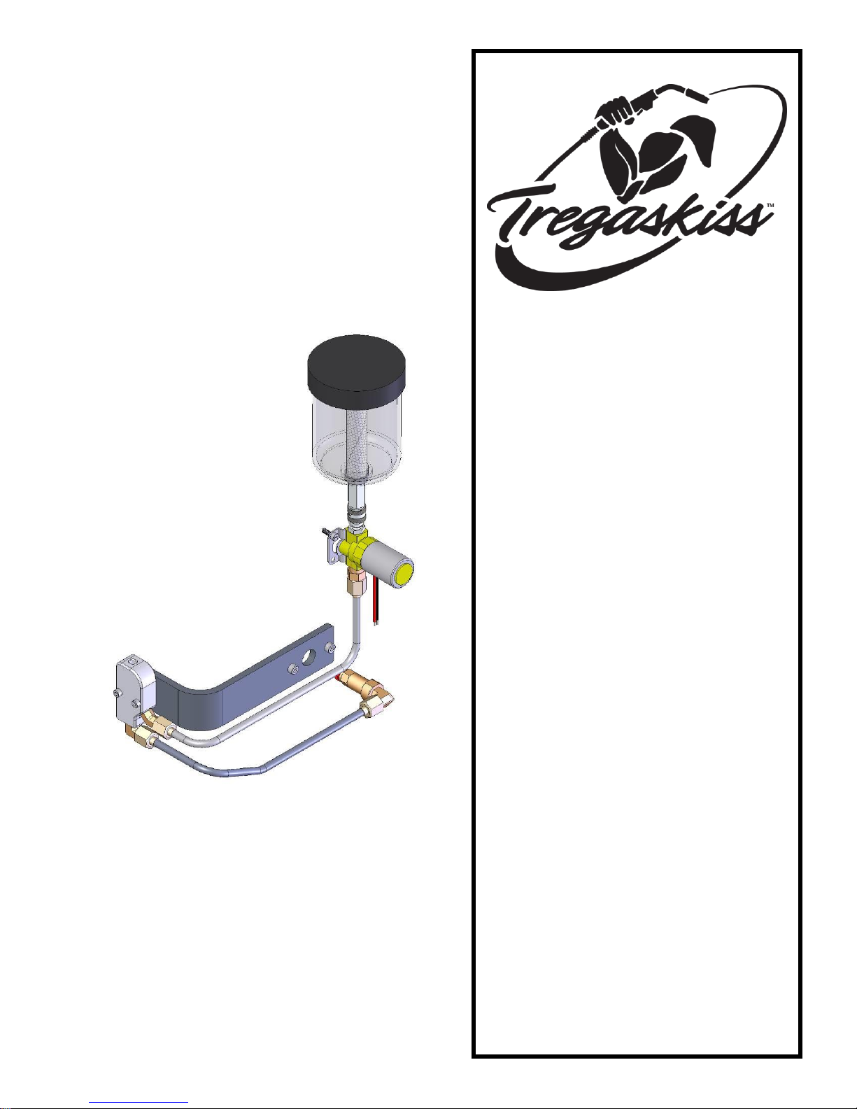
ANTI-SPATTER SPRAYER
SR-500 – for TT Reamer
TS-500 – for Discontinued Reamer
RS-500 – Stand Alone Unit
INSTALLATION
OPERATION
MAINTENANCE GUIDE
TROUBLESHOOTING
TECHNICAL DATA
ASSEMBLY VIEW & PARTS
LIST
ORDERING INFORMATION
Certified ISO9001: 2008
Please read instructions prior to use.
Save this manual for future reference.
Page 2

2
TABLE OF CONTENTS
THANK YOU… ................................................................................................................................... 2
WARRANTY ...................................................................................................................................... 3
GENERAL SAFETY .............................................................................................................................. 3
1.0 – INSTALLATION .......................................................................................................................... 4
1.1 MOUNTING SR-500 SPRAYER FOR NEXT GENERATION TOUGH GUN REAMERS ..................................... 4
1.2 MOUNTING RS-500 SPRAYER (STAND-ALONE UNIT) ............................................................................. 4
1.3 MOUNTING TS-500 SPRAYER FOR DISCONTINUED REAMERS ............................................................... 5
1.4 SR-500 ELECTRICAL AND PNEUMATIC HOOK-UP .................................................................................. 5
1.5 RS-500 ELECTRICAL AND PNEUMATIC HOOK-UP .................................................................................. 6
1.6 TS-500 ELECTRICAL HOOK-UP .............................................................................................................. 6
2.0 – OPERATION .............................................................................................................................. 7
2.1 PROGRAMMING EVENTS SEQUENCE SR-500, RS-500 AND TS-500 ......................................................... 7
3.0 – MAINTENANCE ......................................................................................................................... 7
4.0 – TROUBLESHOOTING ................................................................................................................. 8
5.0 – ASSEMBLY VIEW & PARTS LIST ................................................................................................. 8
5.1 SR-500 SPRAYER FOR NEXT GENERATION TOUGH GUN REAMERS ........................................................ 8
5.2 RS-500 SPRAYER (STAND-ALONE UNIT) ................................................................................................ 9
5.3 TS-500 SPRAYER FOR DISCONTINUED REAMERS .................................................................................. 9
6.0 – ORDERING INFORMATION ...................................................................................................... 10
THANK YOU…
…for selecting a Tregaskiss TOUGH GUN
™
Sprayer. Manufacturing operations demand extremely dependable
robotic equipment. With this in mind, the TOUGH GUN Sprayer was designed and engineered to be a reliable tool to
support high production volumes within a robotic cell. As the name implies, the TOUGH GUN Sprayer is made from
durable materials and components engineered to perform in a rugged, robotic welding environment.
The instructions and illustrations in this technical guide make it easy for you to maintain your TOUGH GUN Sprayer.
Please read, understand, and follow all safety procedures. Keep this Technical Guide booklet as a handy
reference when ordering complete guns, parts and special options.
For technical support and special applications, please call the Tregaskiss Technical Service Department at
1-855-MIGWELD (644-9353) or fax 1-877-737-2111. Our trained technicians are available between 8:00 a.m. and
5:00 p.m. EST and will answer your application or repair questions.
Tregaskiss also manufactures complete robotic MIG guns systems designed and engineered to perform as a team in
the high-volume robotic production environment. Components include TOUGH GUN Robotic Air-Cooled and WaterCooled MIG Guns, TOUGH GUN Clutch and Gun Mounting Arms. Contact your Tregaskiss representative for further
information.
Page 3

3
WARRANTY
Product is warranted to be free from defects in material and workmanship for the period specified below after the
sale by an authorized Buyer. Should there be a defect please refer to our Return Merchandise Policy.
PRODUCT
WARRANTY PERIOD
TOUGH GUN™ Robotic MIG Guns
180 days
TOUGH GUN Reamer
1 year
TOUGH GARD™ Spatter Cleaner
1 year
TOUGH GUN Robotic Peripherals (Clutch, Sprayer, Wire Cutter, Mounting Arms)
1 year
Low-Stress Robotic Unicables (LSR Unicables)
2 years
Tregaskiss reserves the right to repair, replace or refund the purchase price of non-conforming product. Product
found not defective will be returned to the Buyer after notification by Customer Service.
Tregaskiss makes no other warranty of any kind, expressed or implied, including, but not limited to the warranties
of merchantability or fitness for any purpose. Tregaskiss shall not be liable under any circumstances to Buyer, or
to any person who shall purchase from Buyer, for damages of any kind including, but not limited to any, direct,
indirect incidental or consequential damages or loss of production or loss of profits resulting from any cause
whatsoever, including, but not limited to, any delay, act, error or omission of Tregaskiss.
Genuine Tregaskiss parts must be used for safety and performance reasons or the warranty becomes invalid.
Warranty shall not apply if accident, abuse, or misuse damages a product, or if a product is modified in any way
except by authorized Tregaskiss personnel.
GENERAL SAFETY
Before installation or operation of the TOUGH GUN Sprayer, please read and understand all safety precautions
listed below. Failure to follow these instructions may result in personal injury or damage to the equipment.
1. Do not remove or deface warning and instruction labels from the unit.
2. Ensure that all equipment in the area is disabled and locked out before setting up, adjusting or conducting any
work.
3. Ensure that electrical and pneumatic power to unit is off before setting up, adjusting, or conducting any work.
4. Check that electrical and pneumatic connections comply with the codes applicable to your country and state.
5. Keep hands away from unit while in operation.
6. For additional safety information, please refer to the following publications:
ANSI STANDARD Z49.1, SAFETY IN WELDING AND CUTTING,
American Welding Society, 550 LeJeune Rd. P.O. Box 351040, Miami, FL 33126
ANSI STANDARD, SAFETY OR ROBOTS AND ROBOT SYSTEMS,
American National Standards Institute, 1430 Broadway, New York, NY 10018
NFPA STANDARD 70-1978. NATIONAL ELECTRIC CODE,
National Fire Protection Association, 1470 Atlantic Avenue, Boston MA 02210
CALIFORNIA PROPOSITION 65 WARNING
This product, when used for welding or cutting, produces fumes or gases which contain chemicals known to the
State of California to cause birth defects and, in some cases, cancer.
This product contains chemicals, including lead, known to the State of California to cause cancer, and birth
defects or other reproductive harm. Wash hands after use.
(California Health & Safety Code Section 25249.5 at seq.)
Page 4
1.0 – INSTALLATION
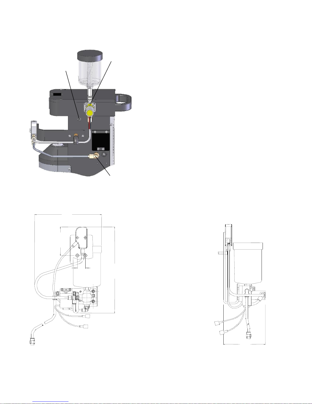
1.1 MOUNTING SR-500 SPRAYER FOR NEXT GENERATION TOUGH GUN REAMERS
The Next Generation TOUGH GUN Reamer has all the
necessary mounting holes for installation of the SR-500
spray unit.
Remove plug from side of frame detail and
replace with bulkhead fitting (supplied).
Attach spray head bracket to Reamer using two
(2) screws (supplied).
Attach spray head to reamer using two (2)
screws (supplied).
Pass wires through grommet and then through
the specified hole in reamer frame.
Plug reservoir into check valve using quick
connect fittings.
1.2 MOUNTING RS-500 SPRAYER (STAND-ALONE UNIT)
The sprayer should be installed within the weld cell at a convenient location. Be sure to consider movable
fixtures and the confines of the robot.
Each sprayer comes complete with all required installation hardware and mounting brackets.
CHECK
VALVE
BULKHEAD
GROMMET
7.0”
(17.78 cm)
9.6”
(24.38 cm)
3.25”
(8.23 cm)
MOUNTING
BRACKET
PART # RS-500-6
.875”
(2.22 cm)
4.4”
(11.18 cm)
Page 5
5
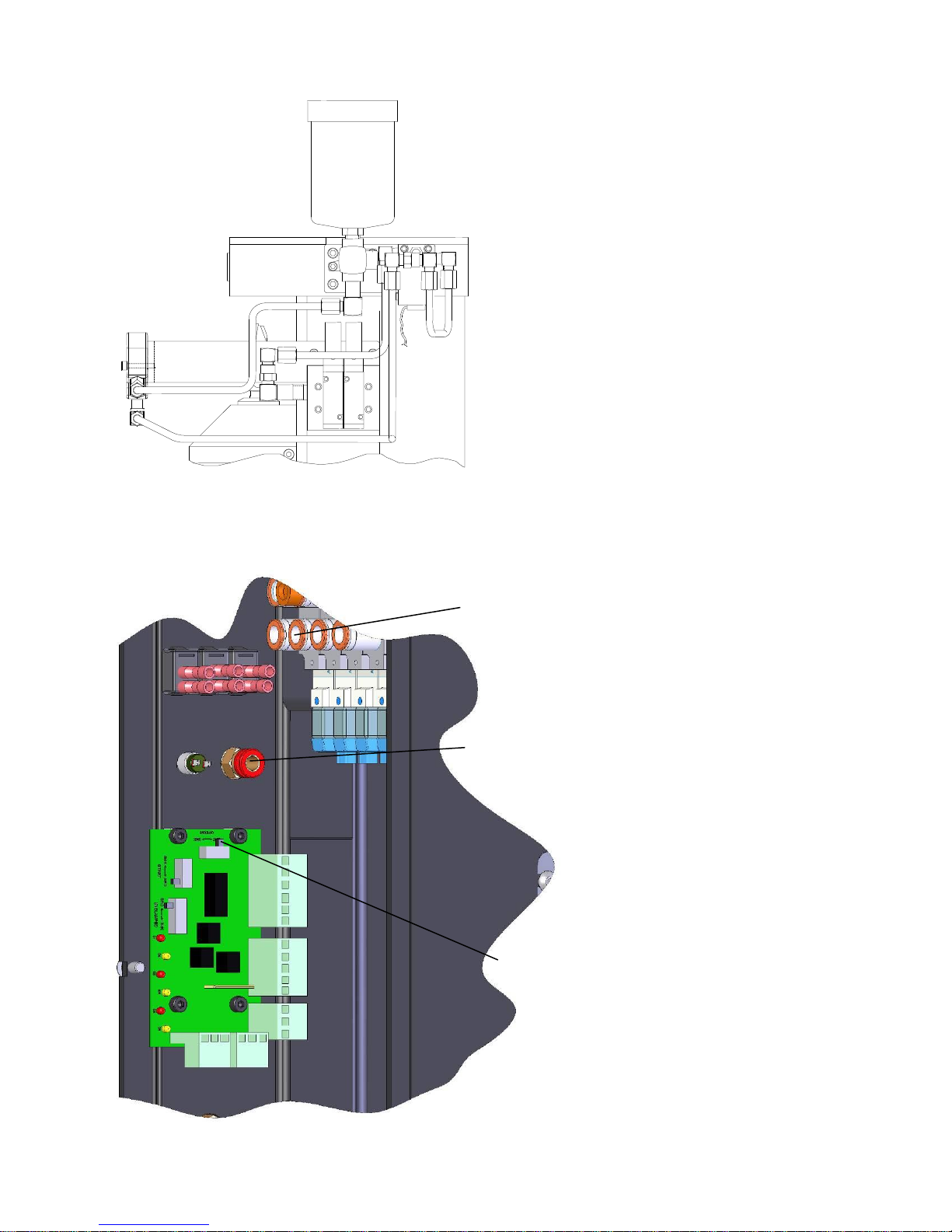
1.3 MOUNTING TS-500 SPRAYER FOR DISCONTINUED REAMERS
The TOUGH GUN Reamer has all necessary
mounting holes for installing the TS-500 spray
unit.
Remove center plug from Reamer valve
package, and replace with 90° air fitting.
Attach spray head bracket to Reamer using
(2) 10-24 screws (supplied).
Attach valve block to Reamer using (2) 1/4”
screws (supplied).
Pass wires through hole in Reamer frame.
Thread reservoir into valve block.
1.4 SR-500 ELECTRICAL AND PNEUMATIC HOOK-UP
ELECTRICAL CONNECTIONS
Set option switch (SW1) to sourcing
or sinking depending on your robot
configuration.
See M064 Reamer Manual (Section
1) for proper switch configuration.
NOTE: Leads are not polarity
sensitive.
PNEUMATIC CONNECTIONS
Install 90 degree fitting into bulkhead
connector on outside of reamer
frame.
Install stainless line kit onto spray
head and to check valve.
Install push-to-connect fitting on other
side of the bulkhead fitting (inside of
reamer frame).
Install 8” piece of 1/4” tubing to push-
to-connect fitting, remove lower plug
from sprayer valve (2nd from left) and
install other end of tubing.
PUSH TO
CONNECT
FITTING
SW1
SWITCH
CONNECT ¼”
TUBING TO
THIS VALVE
Page 6
6
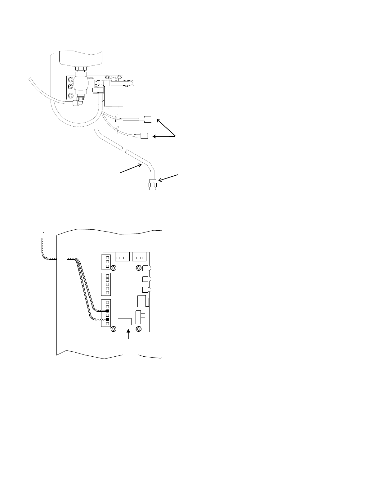
1.5 RS-500 ELECTRICAL AND PNEUMATIC HOOK-UP
ELECTRICAL
To interface the sprayer with
controller, two electrical
connections are required.
1 wire - 24 VDC
1 wire - Ground
PNEUMATIC
Recommended air supply
should be dry filtered air at
80-100 psi (5.0 - 7.0 bar).
1.6 TS-500 ELECTRICAL HOOK-UP
Set option switch (SW1) to sourcing or
sinking depending on your configuration.
See Reamer Technical Manual (pg. 5) for
proper switch configuration.
NOTE: Leads are not polarity sensitive.
SW1
412-4-1
INSULATED MALE
CONNECTOR TYP. (2)
TR-2232
AIR FITTING
LEGRIS #31755611
TR-2250
1/4' AIR LINE
4' LONG
Page 7
7
2.0 – OPERATION
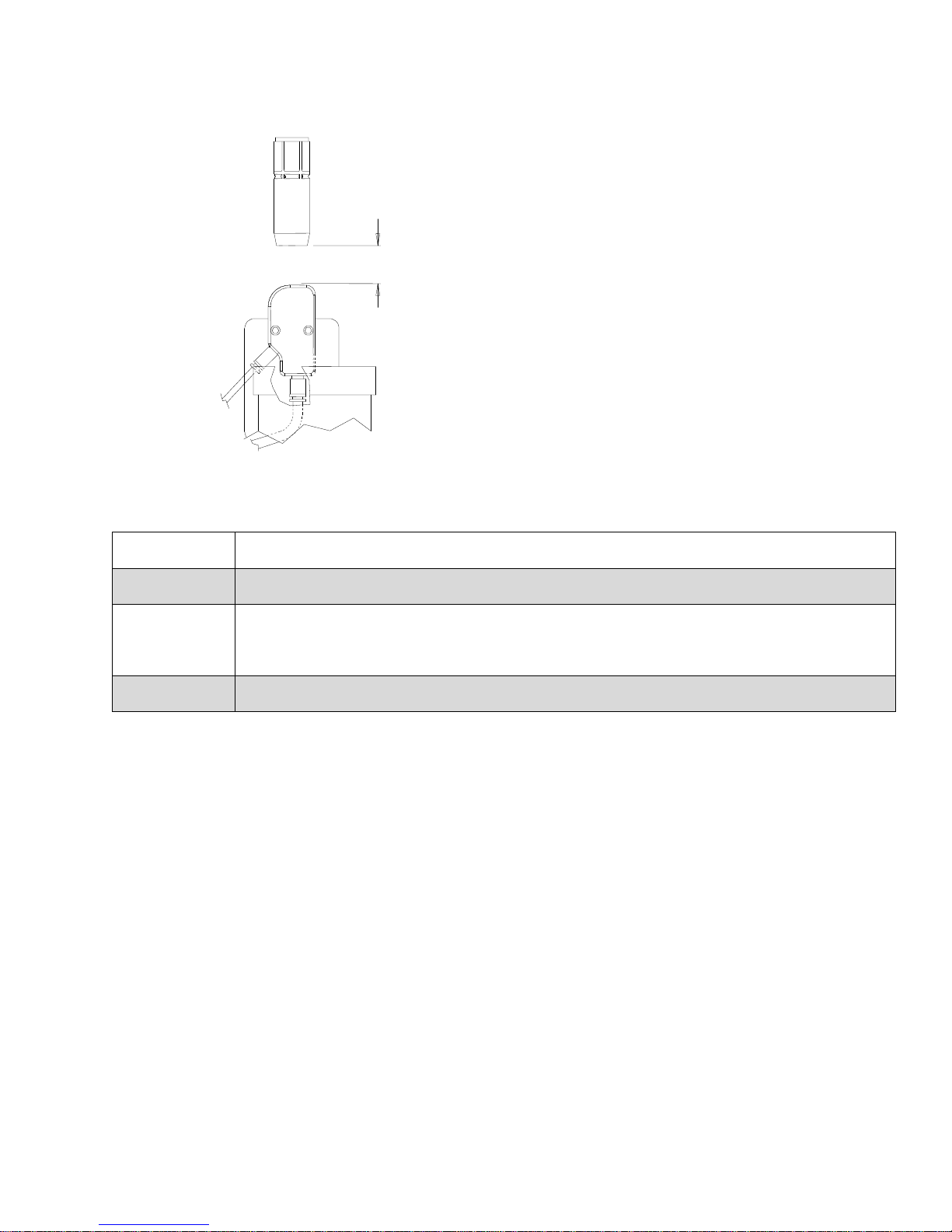
2.1 PROGRAMMING EVENTS SEQUENCE SR-500, RS-500 AND TS-500
Program robot so that nozzle is centrally located 1”
(25 mm) above spray head. Depending on
configuration of nozzle and contact tip, position of
nozzle may have to be adjusted to ensure proper
coverage.
Set output signal initially at 0.5 seconds and adjust
timer as necessary to suit your process.
IMPORTANT: If using Air Blast option on robotic
gun, do not activate when over spray head. Failure
to do so may clog the spray head orifice.
3.0 – MAINTENANCE
DAILY
Ensure fluid level in reservoir is maintained. Inspect spray operation to ensure adequate antispatter compound is being applied.
WEEKLY
Inspect unit for air leaks or damaged supply and interface lines which may cause unit to
malfunction.
QUARTERLY
Inspect unit for build-up of residue from anti-spatter compound which could eventually restrict
fluid flow or cause unit to malfunction. Residue should be visible in reservoir or nozzle
assembly. If excessive, should clean or flush with recommended solvent for anti-spatter
compound.
YEARLY
Inspect unit for damage or excessive wear of components. Replace if required.
(RS-500 shown)
1.00” (25 mm)
GUN NOZZLE
Page 8
8
4.0 – TROUBLESHOOTING
PROBLEM
POSSIBLE CAUSE
SOLUTION
NO AIR FLOW
NO ANTI-SPATTER
OUTPUT TO UNIT NOT
FUNCTIONING
FUSE BLOWN
LOSS OF AIR SUPPLY
FAULTY SOLENOID VALVE
CHECK OUTPUT SIGNAL AND CABLE
INSTALL NEW FUSE
CHECK AIR SUPPLY
CHECK AIRLINE AND NOZZLE FOR
BLOCKAGE
CHECK SOLENOID VALVE AND REPLACE
IF REQUIRED
AIR FLOW BUT NO
ANTI-SPATTER
NOZZLE POSITION
INCORRECT ON SPRAY HEAD
SPOOL IN VALVE BLOCK
STUCK
FLUID LINE BLOCKED
FAULTY CHECK VALVE
INADEQUATE AIR PRESSURE
ADJUST NOZZLE POSITION ON SPRAY
HEAD
REPAIR OR REPLACE VALVE BLOCK
CLEAN OR REPAIR FLUID LINE
REPLACE CHECK VALVE
ENSURE 80 PSI
SPRAY HEAD
PLUGGED
CLEAN SPRAY HEAD
5.0 – ASSEMBLY VIEW & PARTS LIST
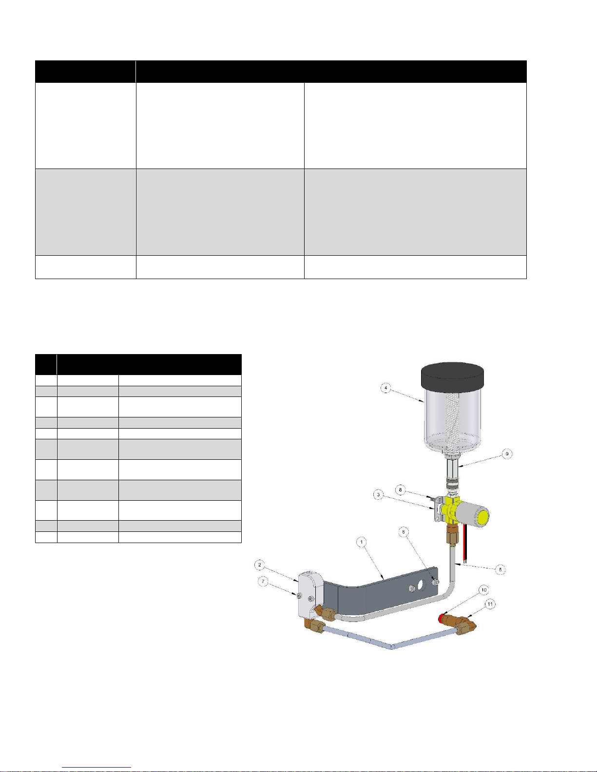
5.1 SR-500 SPRAYER FOR NEXT GENERATION TOUGH GUN REAMERS
PART#
DESCRIPTION
1
SR-500-1
SPRAYER BRACKET
2
TS-500-15
SPRAY HEAD
3
NOT
SELLABLE
CHECK VALVE - SMC P/N
VDW31-5G-4-02N-F
4
RR-1320
RESERVOIR
5
SR-500-50
SPRAYER STEEL LINE KIT
6
NOT
SELLABLE
SHCS - M5 x 0.8 x 16 mm
7
NOT
SELLABLE
SHCS - M4 x 0.7 x25 mm
8
NOT
SELLABLE
SHCS - M4 x 0.7 x12 mm
9
TS-500-40
SPRAYER QUICK
CONNECTS
10
TR-2232
AIR FITTING - 1/4” SMC
11
SR-500-51
BULKHEAD FITTING
Page 9
9
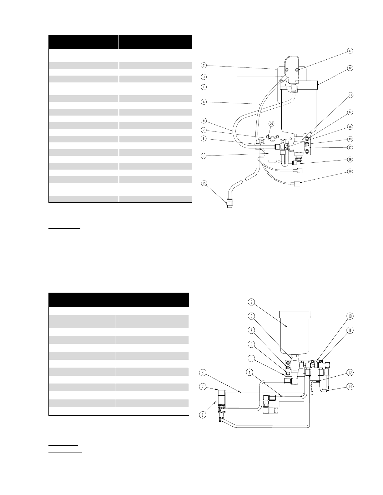
5.2 RS-500 SPRAYER (STAND-ALONE UNIT)
TECHNICAL DATA
Dimensions
Height: 10.8” (274 mm) Width: 8.0” (203 mm)
Depth: 4.4” (112 mm)
Weight: 4.2 lbs. (9.2 kgs)
Electrical: 24 volts DC, 2.5 watts
Pneumatic: 80-90 PSI at 16 C.F.H.
PART #
DESCRIPTION
1
RS-500-1
SPRAY HEAD (WITH AIR
FITTINGS)
2
RS-500-6
BRACKET
3
RS-500-23
AIR FITTING
4
TR-2322
AIR FITTING
5
TS-500-30
AIR LINE - 5/32" (4'
LONG)
6
TR-2250
AIR LINE - 1/4" (4' LONG)
7
RS-500-20
VENT PLUG
8
TR-2235
AIR FITTING (2 REQ'D.)
9
TS-500-28
SOLENOID VALVE
10
TR-2232
AIR FITTING
11
NOT SELLABLE
10-24 x 1” S.H.C.S.
12
RR-1320
RESERVOIR
13
TS-500-20
CHECK VALVE
14
NOT SELLABLE
1/4-20 x 0.75” S.H.C.S.
15
NOT SELLABLE
10-24 x 1/4” S.H.C.S.
16
TS-500-24
AIR FITTING
17
TS-500-29
MOUNTING PLATE
18
TS-500-27
AIR FITTING
19
412-4-1
INSULATED MALE
CONNECTOR
20
NOT SELLABLE
8-32 x 1 1/8” S.H.C.S.
5.3 TS-500 SPRAYER FOR DISCONTINUED REAMERS
TECHNICAL DATA
Electrical: 24 volts DC, 2.5 watts
Pneumatic: 80 - 100 psi at 16 CFM
(same supply as TOUGH GUN Reamer)
PART #
DESCRIPTION
1
NOT SELLABLE
10-24 x 1” S.H.C.S.
2
TS-500-15
SPRAY HEAD (WITH
FITTINGS)
3
TS-500-1
SPRAY HEAD BRACKET
4
NOT SELLABLE
10-24 x 5/8” S.H.C.S.
5
TS-500-29
MOUNTING PLATE
6
NOT SELLABLE
1/4-20 x 0.75” S.H.C.S.
7
NOT SELLABLE
10-24 x 1/4” S.H.C.S.
8
TS-500-20
CHECK VALVE
9
RR-1320
RESERVOIR
10
RS-500-20
VENT PLUG
11
NOT SELLABLE
8-32 x 1 1/8” S.H.C.S.
12
TS-500-28
SOLENOID VALVE
13
TS-500-50
STEEL LINE KIT
Page 10
10
6.0 – ORDERING INFORMATION
PART #
DESCRIPTION
SR-500
Next Generation TOUGH GUN Reamer Mounted Sprayer
RS-500
Optional Stand Alone Sprayer Unit
TS-500
Mounted Sprayer for Discontinued Reamer Styles
Distributed by:
07/10
M027 REV D
 Loading...