

Page 1
Page 2

Technical Manual – TM1/TM2 | MA-010| 2016-03-21 | Ver.: 6.30 2
Temperature Monitor
Table of contents
1 FOREWORD .................................................................................................................................................... 6
1.1 LEGAL INFORMATION ................................................................................................................................................ 6
1.2 PRESENTATION ........................................................................................................................................................ 6
1.3 TYPOGRAPHICAL CONVENTIONS .................................................................................................................................. 6
1.4 GENERAL AND SAFETY INFORMATION........................................................................................................................... 6
Safety Symbols ..................................................................................................................................................... 7
General Symbols ................................................................................................................................................... 7
Minimum profile recommended for the TM1/TM2 operator and maintainer ..................................................... 7
Environmental and voltage conditions required for installation and operation .................................................. 8
Instructions for test and installation .................................................................................................................... 8
Cleaning and decontamination instructions ......................................................................................................... 9
Inspection and Maintenance instructions ............................................................................................................ 9
1.5 TECHNICAL ASSISTANCE .......................................................................................................................................... 10
1.6 WARRANTY TERM .................................................................................................................................................. 11
1.7 REVISION CONTROL ................................................................................................................................................ 12
2 INTRODUCTION .............................................................................................................................................13
2.1 MAIN FEATURES .................................................................................................................................................... 13
2.2 OPTIONAL FEATURES .............................................................................................................................................. 15
2.3 OPERATION PHILOSOPHY ......................................................................................................................................... 16
3 OPERATION ...................................................................................................................................................19
3.1 INITIAL SETTINGS ................................................................................................................................................... 19
3.2 FUNCTION OF KEYS ................................................................................................................................................ 21
3.3 CONSULTATION SCREENS ......................................................................................................................................... 21
TM1 Consultation Screens .................................................................................................................................. 21
Consultation Screen TM2 ................................................................................................................................... 23
3.4 COMMANDS ......................................................................................................................................................... 24
4 PROJECT AND INSTALLATION ........................................................................................................................26
4.1 SYSTEM TOPOLOGY ................................................................................................................................................ 26
4.2 INPUTS AND OUTPUTS ............................................................................................................................................ 26
4.3 PROJECT AND INSTALLATION .................................................................................................................................... 28
RTD Temperature Sensors .................................................................................................................................. 29
Serial Communication Ports RS485 .................................................................................................................... 30
Analogic Outputs ................................................................................................................................................ 31
Current Transformers ......................................................................................................................................... 31
Forced Cooling Control ....................................................................................................................................... 33
4.4 TYPICAL APPLICATION DIAGRAMS ............................................................................................................................. 41
4.5 MECHANICAL INSTALLATION .................................................................................................................................... 46
5 PARAMETERIZATION .....................................................................................................................................47
5.1 PROGRAMMING .................................................................................................................................................... 47
5.2 ACCESS TO THE PROGRAMMING MENU ...................................................................................................................... 48
5.3 ACCESS TO SUBMENUS ............................................................................................................................................ 49
Submenu LNG ..................................................................................................................................................... 50
Submenu CLK ...................................................................................................................................................... 50
Submenu ALM .................................................................................................................................................... 51
Submenu CNF ..................................................................................................................................................... 53
Submenu TRF ...................................................................................................................................................... 61
Page 3

Technical Manual – TM1/TM2 | MA-010| 2016-03-21 | Ver.: 6.30 3
Temperature Monitor
Submenu FAN ..................................................................................................................................................... 65
Submenu LTC ...................................................................................................................................................... 69
Submenu LOG ..................................................................................................................................................... 71
5.4 TYPICAL ADJUSTS ................................................................................................................................................... 73
6 START-UP PROCEDURE FOR PUTTIN EQUIPMENT IN OPERATION .................................................................74
7 TROUBLESHOOTING ......................................................................................................................................80
7.1 THE DEVICE DISPLAYS SELF-DIAGNOSIS MESSAGES ON THE DISPLAY ................................................................................... 80
7.2 TM1/TM2 READS INCORRECT VALUES FOR TEMPERATURES ........................................................................................... 87
7.3 TM1/TM2 READS INCORRECTLY VALUES FOR LOAD CURRENTS ....................................................................................... 88
7.4 TM1/TM2 INDICATES INCORRECT VALUES FOR WINDING TEMPERATURES ........................................................................ 88
7.5 TM1 DOES NOT COMMUNICATE WITH THE DATA ACQUISITION SYSTEM ............................................................................. 88
7.6 REMOTE READING THROUGH ANALOG OUTPUT INCORRECT ............................................................................................. 89
7.7 TM1/TM2 DOES NOT CORRECTLY ACTIVATE THE FORCED COOLING ................................................................................. 89
8 ATTACHMENTS .............................................................................................................................................90
8.1 ATTACHMENT A .................................................................................................................................................... 90
8.2 ATTACHMENT B ..................................................................................................................................................... 91
8.3 ATTACHMENT C ..................................................................................................................................................... 92
8.4 ATTACHMENT D .................................................................................................................................................... 93
Page 4

Technical Manual – TM1/TM2 | MA-010| 2016-03-21 | Ver.: 6.30 4
Temperature Monitor
List of figures
FIGURE 1 – TEMPERATURE MONITORS TM1 AND TM2 ............................................................................................................... 14
FIGURE 2 – TEMPERATURE MEASUREMENTS OF LTC, TRANSFORMER AND TEMPERATURE DIFFERENTIAL ................................................. 17
FIGURE 3 - INSTANTANEOUS AND FILTERED TEMPERATURE DIFFERENTIALS ....................................................................................... 18
FIGURE 4 – TEMPERATURE INDICATIONS .................................................................................................................................... 19
FIGURE 5 – SIGNALING LEDS ON TEMPERATURE MONITOR TM1 ................................................................................................... 20
FIGURE 6 – SIGNALING LEDS ON TEMPERATURE MONITOR TM2 ................................................................................................... 20
FIGURE 7 – SELF-DIAGNOSTIC INDICATIONS ................................................................................................................................ 21
FIGURE 8 – BLOCK DIAGRAM ................................................................................................................................................... 26
FIGURE 9 – DETAIL SHIELD CONNECTION OF RTD SENSOR ............................................................................................................ 30
FIGURE 10 – SHIELD CONNECTION OF SERIAL COMMUNICATION...................................................................................................... 31
FIGURE 11 – CONNECTION DETAILS OF CURRENT TRANSFORMERS DIRECTLY TEMPERATURE MONITORS .................................................. 32
FIGURE 12 – CONNECTION DETAILS OF CURRENT TRANSFORMERS TO TEMPERATURE MONITORS PREPARED FOR EXTERNAL CILIP-ON CTS ...... 33
FIGURE 13 – COMMAND OF 4 EQUAL FORCED COOLING GROUPS SHIFTING THE OPERATION OF GROUPS ................................................. 35
FIGURE 14 – COMMAND OF 1 FORCED COOLING GROUP WITH PUMPS AND 3 EQUAL GROUPS WITH FANS SHIFTING THE OPERATION OF FAN
GROPS ........................................................................................................................................................................ 36
FIGURE 15 – COMMAN OF 2 EQUAL FORCED COOLING GROUPS WITH PUMPS AND 2 EQUAL GROUPS WITH FANS, WITH INDEPENDENTE SHIFTING
FOR THE OPERATION OF THE PUMP GROUPS AND THE FAN GROUPS.......................................................................................... 37
FIGURE 16 – COMMAND OF 4 EQUAL FORCED COOLING GROUPS IN 2 TEMPERATURE STAGES, WITH TIMER FOR MOTORS START AND SHIFTING
THE GROUPS ................................................................................................................................................................ 39
FIGURE 17 – COMMAND OF 2 EQUAL FORCED COOLING GROUPS WITH COMMAND REDUNDANCY ......................................................... 40
FIGURE 18 – OPTION 1 – 2 RTDS WITH 3 WIRES ......................................................................................................................... 41
FIGURE 19 - OPTION 2 – 1 RTD WITH 4 WIRES .......................................................................................................................... 42
FIGURE 20 – OPTION 3 – 1 RTD WITH 3 WIRES, RTD A ............................................................................................................... 43
FIGURE 21 – OPTION 4 – 1 RTD WITH 3 WIRES, RTD B ............................................................................................................... 43
FIGURE 22 – CONNECTION TM1/TM2 ..................................................................................................................................... 44
FIGURE 23 – CONNECTION TM1 / MT2 ................................................................................................................................... 44
FIGURE 24 – CONNECTION MT1 / TM2 ................................................................................................................................... 45
FIGURE 25 – CONNECTION TM1 / SYNCHRONISM SIGNAL IRIG-B .................................................................................................. 45
FIGURE 26 – DIMENSIONS OF TM1 AND TM2 ........................................................................................................................... 46
FIGURE 27 – SELF-DIAGNOSTIC INDICATIONS .............................................................................................................................. 80
Page 5

Technical Manual – TM1/TM2 | MA-010| 2016-03-21 | Ver.: 6.30 5
Temperature Monitor
List of Tables
TABLE 1 – OPERATING CONDITIONS ............................................................................................................................................ 8
TABLE 2 – REVISION CONTROL ................................................................................................................................................. 12
TABLE 3 – TM1/TM2 INPUTS ................................................................................................................................................. 27
TABLE 4 - TM1/TM2 OUTPUTS ............................................................................................................................................... 28
TABLE 6 – DIGIT 1 FAILURES .................................................................................................................................................... 81
TABLE 7 – DIGIT 2 FAILURES .................................................................................................................................................... 82
TABLE 8 – DIGIT 3 FAILURES .................................................................................................................................................... 84
TABLE 9 – DIGIT 4 FAILURES .................................................................................................................................................... 86
TABLE 10 – INCORRECT READING OF VALUES FOR TEMPERATURES ................................................................................................... 87
TABLE 11 – INCORRECTLY VALUES FOR LOAD CURRENTS ................................................................................................................ 88
TABLE 12 – INCORRECT VALUES FOR WINDING TEMPERATURES ....................................................................................................... 88
TABLE 13 – NO COMMUNICATION BETWEEN TM1 AND DATA ACQUISITION SYSTEM .......................................................................... 88
TABLE 14 – REMOTE READING THROUGH ANALOG OUTPUT INCORRECT ............................................................................................ 89
TABLE 15 - INCORRECT ACTIVATE THE FORCED COOLING ................................................................................................................ 89
TABLE 16 – COMPATIBILITY BETWEEN FIRMWARES ....................................................................................................................... 93
Page 6

Technical Manual – TM1/TM2 | MA-010| 2016-03-21 | Ver.: 6.30 6
Temperature Monitor
1 Foreword
1.1 Legal Information
The information contained in this document is subject to changes without prior notice.
This document belongs to Treetech Sistemas Digitais Ltda. and may neither be copied,
transferred to third parties nor used without express authorization, in terms of law 9.610/98.
Disclaimer:
Treetech Sistemas Digitais reserves the right to make changes without prior notice in all
products, circuits and functionalities described herein with the aim of improving their
reliability, function or design. Treetech Sistemas Digitais does not assume any liability resulting
from application or use of any product or circuit described herein, and does not transmit any
licenses or patents under its rights, not even third party rights.
Treetech Sistemas Digitais Ltda. may own patent or other types of registrations and intellectual
property rights described in the content of this document. Possession of this document by any
person or entity does not give such person or entity any right over these patents or
registrations.
1.2 Presentation
This manual presents all the recommendations and instructions for installation, operation and
maintenance of the Temperature Monitor – TM1/TM2.
1.3 Typographical Conventions
Throughout this text, the following typographical conventions were adopted:
Bold: Symbols, terms and words that are in bold have greater contextual importance.
Therefore, pay attention to these terms.
Italics: Terms in foreign language, alternative or with their use outside the formal situation are
written in italics.
1.4 General and Safety Information
This section presents relevant aspects of safety, installation and maintenance of the TM1/TM2.
Page 7
Technical Manual – TM1/TM2 | MA-010| 2016-03-21 | Ver.: 6.30 7
Temperature Monitor
Safety Symbols
This manual uses three types of risk classification, as shown below:
Caution
The Caution symbol is used to alert the user of a potentially hazardous operating or maintenance
procedure that demands greater caution in its conduction. There may be minor or moderate injuries, as
well as damages to the equipment.
Warning
The Warning symbol is used to alert the user of a potentially hazardous operating or maintenance
procedure in which extreme caution must be taken. There may be serious injuries or death. Possible
damages to the equipment are irreparable.
Electric Shock Hazard
The Electric Shock Hazard symbol is used to alert the user of an operating or maintenance procedure
that may result in electric shock if not strictly observed. There may be minor, moderate, serious injuries
or death.
General Symbols
This manual uses the following general symbols:
Important
The Important symbol is used to highlight relevant information.
Tip:
The Tip symbol represents instructions that facilitate use and access of functions in the TM1/TM2.
Minimum profile recommended for the TM1/TM2 operator and maintainer
Installation, maintenance and operation of equipment in electric power substations require
special cares and, therefore, all recommendations of this manual, applicable standards, safety
procedures, safe work practices and good judgment must be used during all handling stages of
the Temperature Monitor (TM1 and TM2).
For use of this manual, an authorized and trained person has knowledge of the inherent risks –
both electrical and environmental – involved in handling the TM1 and TM2.
Only authorized and trained personnel – operators and maintainers – should handle this equipment.
Page 8
Technical Manual – TM1/TM2 | MA-010| 2016-03-21 | Ver.: 6.30 8
Temperature Monitor
a) The operator or maintainer must be trained and authorized to operate,
ground, turn on and turn off the TM1/TM2, following maintenance procedures
according to the safety practices established, under the sole responsibility of the
TM1/TM2 operator and maintainer;
b) Be trained in the use of IPEs, CPEs and first-aid;
c) Trained in the working principles of the TM1 and TM2, as well as its
configuration.
d) Follow regulatory recommendations regarding interventions in any type of
equipment included in an Electric Power System.
Environmental and voltage conditions required for installation and operation
The table below lists important information on the environmental and voltage requirements:
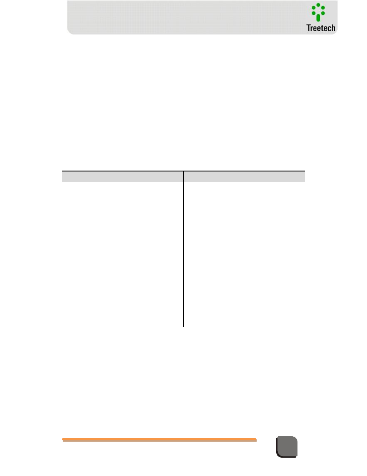
Table 1 – Operating Conditions
Condition
Interval/Description
Application
Equipment for sheltered use in substations, industrial
environments and similar.
Internal/External Use
Internal Use
Degree of Protection (IEC 60529)
IP 20
Altitude* (IEC EN 61010-1)
Up to 2000 m
Temperature (IEC EN 61010-1)
Operation
-40 °C to +85 °C
Storage
-50 °C to +95 °C
Relative Humidity (IEC EN 61010-1)
Operation
5% to 95% – Uncondensed
Storage
3% to 98% – Uncondensed
MAINS Supply Voltage Fluctuation (IEC EN 61010-1)
Up to ±10% of the Rated voltage
Overvoltage (IEC EN 61010-1)
Category II
Level of Pollution (IEC EN 61010-1)
Level 2
Atmospheric Pressure** (IEC EN 61010-1)
80 kPa to 110 kPa
* Altitudes greater than 2000 m already have successful applications.
* Pressures of less than 80 kPa already have successful applications.
Instructions for test and installation
This manual must be available to those responsible for installation, maintenance and users
of the Temperature Monitor – TM1/TM2.
To guarantee user safety, equipment protection and correct operation, the following minimum
cares must be followed during the TM1/TM2 installation and maintenance:
1. Read this manual carefully before installation, operation and maintenance of
the TM1/TM2. Errors in installation, maintenance or adjustments of the TM1/TM2
Page 9
Technical Manual – TM1/TM2 | MA-010| 2016-03-21 | Ver.: 6.30 9
Temperature Monitor
can cause undue operations of the tap changer in load, unsatisfactory voltage
regulation, undue alarms or pertinent alarms may also fail to be emitted.
2. The installation, adjustments and operation of the TM1/TM2 must be done by
personnel trained and acquainted with the electric motors, power transformers,
tap changers on load or voltage regulators, control devices and control circuits of
substation equipment.
3. Special attention must be paid to installation of the TM1/TM2, including the
type and size of the cables and terminal strips used, as well as the procedures
for commissioning, including correct parameterization of the equipment.
The TM1/TM2 must be installed in a sheltered environment (a panel without doors in a control room or
in a closed panel, in cases of outdoor installation) where the temperature and humidity specified for the
equipment are not exceeded.
Do not install the TM1/TM2 near sources of heat like heat resistors, incandescent lamps and devices
with high power or with heat dissipaters. Its installation near ventilation orifices or where it can be
affected by forced air flow, like outlet or inlet of cooling fans or forced ventilation ducts, is not
recommended.
On conducting dielectric strength tests on the wiring (applied voltage), the ground cables connected to
terminal 17 of the TM1/TM2 must be disconnected in order to prevent destruction of the protections
against overvoltage existing inside the device due to application of high voltages for a long period (e.g.:
2 kV for 1 minute).
Cleaning and decontamination instructions
Take care when cleaning the TM1/TM2. Use ONLY a cloth wet with soap or detergent diluted
in water to clean the cabinet, front plate or any other part of the equipment. Do not use
abrasive materials, polishers or aggressive chemical solvents (like alcohol or acetone) on any of
its surfaces.
Turn off and unplug the equipment before cleaning any of its parts.
Inspection and Maintenance instructions
The following observations must be followed for inspection and maintenance of the TM1/TM2:
If the panel where the TM1 / TM2 was installed has a window , use a G20 film - or higher - to avoid
direct incidence of sunlight ( UV ) at the equipment . Even if the glass of this window is dark, such
procedure is necessary.
Page 10

Technical Manual – TM1/TM2 | MA-010| 2016-03-21 | Ver.: 6.30 10
Temperature Monitor
Do not open the equipment. In it, there are no parts reparable by the user. This should be done by the
Treetech technical assistance, or by technicians accredited by it.
This equipment is completely maintenance-free, being that visual and operational inspections,
periodical or not, may be conducted by the user. These inspections are not mandatory.
Opening of the TM1/TM2 at any time will imply in loss of the product warranty. In cases of undue
opening of the equipment, Treetech will also not be able to warrant its correct functioning, regardless of
the warranty period having expired or not.
All parts of this equipment must be supplied by Treetech, or by one of its accredited suppliers,
according to its specifications. If the user wishes to purchase it otherwise, he must strictly follow
Treetech’s recommendations for this. This way, the performance and safety for the user and the
equipment will not be compromised. If these specifications are not followed, the user and the
equipment may be exposed to unforeseen and unnecessary risks.
1.5 Technical Assistance
To obtain technical assistance for the TM1/TM2 or any other Treetech product, contact us
through the address below:
Treetech Sistemas Digitais Ltda. – Assistência Técnica
Rua José Alvim, 100 – Salas 03 e 04 – Centro
Atibaia – São Paulo – Brazil
Zip Code: 12940-800
CNPJ [Corporate taxpayer's roll]: 74.211.970/0002-53
IE [State Tax ID]: 190.159.742.110
PHONE: +55 (11) 2410-1190 x201
FAX: +55 (11) 2410-1190 x702
Email: [email protected]
Site: http://www.treetech.com.br
Page 11

Technical Manual – TM1/TM2 | MA-010| 2016-03-21 | Ver.: 6.30 11
Temperature Monitor
1.6 Warranty term
The Temperature Monitor is guaranteed by Treetech for the term of 2 (two) years, counted
from the date of purchase, exclusively against eventual manufacture defects or quality vices
that render the equipment unfit for use.
The warranty will not cover damages sustained by the product, as a consequence of accidents,
improper handling, incorrect installation and use, inadequate tests or in case the warranty seal
has been breached.
The eventual need for technical assistance must be informed to TREETECH, or to a technical
assistance service appointed by the same, with the equipment being delivered together with
the purchase invoice.
Treetech does not supply, nor is liable to, any other warranty, express or understood, in
addition to the ones mentioned above. Treetech does not supply any guarantee of suitability
of the TM1/TM2 to any specific application.
The dealer is not liable to any claims for damage to property, nor any other form of losses that
might occur, in connection to or stemming from the acquisition of the equipment, of the
performance of the equipment or of any other service possibly supplied together with the
TM1/TM2.
Under no circumstances will the dealer be made responsible for any losses incurred, included
but not limited to: loss of profit or revenue, impossibility in using the TM1/TM2 or any other
associated item of equipment, costs of capital, costs of energy acquired, costs of replacement
equipment, facilities or services, costs of outages, complaints from clients or employees of the
buyer, regardless of whether said damages, complaints or losses are based on contracts,
warranties, negligence, felony or any other reason.
Under no circumstances can the dealer be made liable for any personal damage of any sort.
Page 12
Technical Manual – TM1/TM2 | MA-010| 2016-03-21 | Ver.: 6.30 12
Temperature Monitor
1.7 Revision Control
Table 2 – Revision Control
Revision
Issued
Description
Author
2
2004-11-11
Add submenu PRT (serial communication protocol selection)
and review control page. General text revision.
Note: This manual version is applied just for Temperature
Monitor with firmware V2.0.2
Fco
3
2004-12-08
Included optional functions of forced cooling, clock and
calendar, DNP3.0 information.
Note: This manual version is applied just for Temperature
Monitor with firmware V2.0.4
Fco
4
2005-07-15
Setting range of TRC parameter changed (chapters 5.3.4.1
and 5.3.4.2). Added Modbus registers 67...72.
Note: This manual version is applicable only to Temperature
Monitor with firmware V2.0.7 and higher (unless a specific
manual version is available)
Marcos
5
2006-10-31
Recommendations for insulation tests and parameter sheets
included. Revised temperature scale, register maps and
troubleshooting. General text revision.
Note: This manual version is applicable only to Temperature
Monitor with firmware V3.0.0 and higher (unless a specific
manual version is available)
Marcos
6
2007-06-01
Optional functions Mass Memory and LTC Temperature
Differential included.
Note: This manual version is applicable only to Temperature
Monitor with firmware V4.0.0 and higher (unless a specific
manual version is available)
Marcos
7
2008-04-14
Revised DNP3.0 Device Profile – Analog Inputs 42-49 and
Binary Inputs 64-71 included.
Revised Modbus Register Map – registers 1025-1031, 1505
and 1506 included. Added figures 4.4.and 4.5.
Note: This manual version is applicable only to Temperature
Monitor with firmware V4.0.3 and higher (unless a specific
manual version is available)
Marcos
8
2008-07-15
Revised Forced Cooling control, chapters 2.2, 3.1, 3.4, 4.1,
4.2, 4.2.4, 4.3, 5.3, 5.3.5, 5.3.5.1, 5.3.5.2, 7.7 and Apendix D.
Note: This manual version is applicable only to Temperature
Monitor with firmware V4.0.5 and higher (unless a specific
manual version is available)
Marcos
9
2013-01-15
Aditional functions PBT, SCT, BG1...BG4 included.
Some menus were divided in submenus.
Note: This manual version is applicable only to Temperature
Monitor with firmware V5.0.0 and higher (unless a specific
manual version is available)
William Botelho
10
2015-05-21
International Representatives updated
João V. Miranda
11
2015-07-06
New design; parameterization updated; compatible with 4.16
firmware.
João V. Miranda
12
2015-09-17
Procedure for film installation added
João V. Miranda
13
2016-01-20
Figure 26 (Dimensions) Updated
João V. Miranda
14
2016-03-21
Connection Diagram Updated
João V. Miranda
Page 13

Technical Manual – TM1/TM2 | MA-010| 2016-03-21 | Ver.: 6.30 13
Temperature Monitor
2 Introduction
The Treetech's TM Temperature Monitors form a complete Temperature Monitoring system
for transformers and reactors immersed in oil. Designed as a modular system, it can be used in
simple, low cost applications, as well as in complete monitoring systems. The system is
comprised of modules TM1 and TM2:
TM1 monitors the temperature of the oil and one winding. The device is equipped
with:
- Configurable input for one 4-lead RTD sensor, for oil temperature, or two 3-lead
sensors - redundant reading of oil temperature or simple reading for oil
temperature and one additional temperature (e.g.: ambient or LTC);
- One load current measuring input, for calculating temperature of the winding.
TM2, applied as complement to TM1, monitors the temperature of one or two
additional windings. It is equipped with:
- Two current measuring inputs, for calculating the temperature of two additional
windings;
- Configurable input for one 4-lead RTD sensor, one 3-lead RTD sensor in input A,
one 3-lead RTD sensor in input B or two 3-lead sensors in inputs A and B for
reading additional temperatures (e.g.: ambient, LTCs or others).
Além destas funções básicas, estão disponíveis nos monitores TM1 e TM2 diversos opcionais.
Vide Funções Opcionais adiante.
2.1 Main Features
Input for Pt100 ohms at 0ºC sensors with self-calibration, precision of 0.2% of the end of
scale and high level of stability in a broad range of ambient temperatures.
Oil temperature measurement using one three-wire Pt100 sensor, one four wire Pt100
or two three-wire Pt100 (redundant temperature measurement and validation of the
reading);
Universal AC current inputs True RMS from 0 to 10A, precision 0.5% of full scale for load
measurement and calculation of temperature in the winding through the thermal image
process. Optional clip-on current transformers;
High luminosity, LED type displays for easy visualization, indicating oil, winding and
other user selected temperatures;
Page 14
Technical Manual – TM1/TM2 | MA-010| 2016-03-21 | Ver.: 6.30 14
Temperature Monitor
Calculation of forecast for final oil-winding temperature gradient for current load
condition;
Current outputs for remote temperature readings, with selection of output range
(0...1mA, 0...5mA, 0...10mA, 0...20mA or 4...20mA);
Selectable cooling system operation via front panel on Automatic or Manual. Automatic
alternation in operation of forced cooling groups in pre-programmed stages, based on
their operation times , affording uniform use of fans or pumps;
Optional Pre-cooling function for reducing insulation loss of life due to elevated loads;
Optional Fan Exercise function for prevention of failures in cooling fans or pumps;
NO contacts (NC or combinations upon request) for oil or winding temperature alarms;
NO contacts (NC or combinations upon request) for tripping due to oil and/or winding
temperatures with double activation safety (simultaneous order from the 2 microcontrollers for the operation). Adjustable timing between 0 and 20 min with countdown
on display;
NC contacts for activation of forced cooling groups with timer between start up for
groups (even with lack of feed for TM1 or TM2) and forced operation resulting from selfdiagnosis routines in case of failure or absence of voltage (power outage);
NC contacts for indication of internal failure or lack of voltage detected in self-diagnosis;
NO contacts for indication of count down mode for trip activation or alarm by LTC
temperature differential;
Modbus-RTU (standard) or DNP 3.0 (optional) serial communication protocols.
Protocol DNP-3.0 (optional) with time stamp with 1ms resolution for events like alarms
and trips, based on synchronicity by GPS signal clock on standard IRIG-B (only for TM1)
or synchronicity by the protocol DNP3.0;
Non volatile mass memory for storage of temperature readings, alarm or trip events and
forced cooling operation;
Internal clock with settings maintained for 48h in case of failure of power supply. No
batteries are used - maintenance-free device.
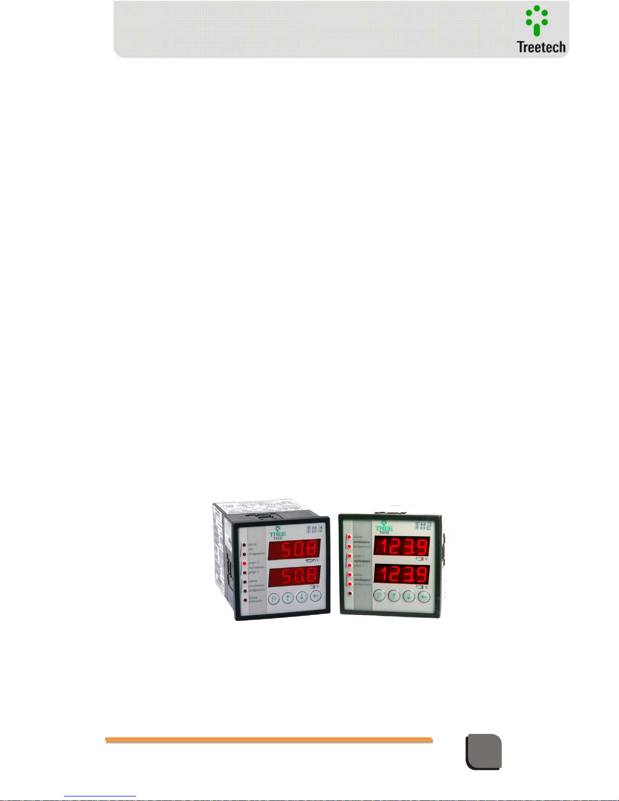
Figure 1 – Temperature Monitors TM1 and TM2
Page 15

Technical Manual – TM1/TM2 | MA-010| 2016-03-21 | Ver.: 6.30 15
Temperature Monitor
2.2 Optional Features
According to the order, the TM1/TM2 can be supplied with one or more of the optional
features listed below:
Optional 1 – DNP 3.0 protocol:
User selectable communication protocol: Modbus RTU or DNP3.0 level 1. DNP3.0 protocol with
support for 1ms resolution time-stamp.
Optional 2 – Pre-Cooling:
Pre-cooling can extend the insulation useful life of transformers subject to overloading by
activating cooling groups when user selected load levels are reached. Taking advantage of the
large thermal inertia of the oil, the forced cooling systems are activated even before the
temperature rises, thus increasing the time required to reach high temperature levels, which
would cause accelerated shortening of insulation life cycle. The following parameters are
programmed by users:
Loading percentages for individual activation of up to four cooling stages;
Hysteresis for shut off of forced cooling stages in case of load reduction.
Optional 3 – Fan and Pump Exercise:
The fan exercise function keeps fans and / or pumps from remaining inactive for prolonged
periods of time in transformers operating under low load conditions or during periods of low
ambient temperatures. This avoids axle blocking due to accumulation of dirt, grease dry out or
bird nesting. Fans are switched on every day, based on the equipment's internal clock and
depending on selections made by users:
Hour and minute for start up of fans and/or pumps;
Total daily fan and/or pump operation time, from 0 to 999 minutes.
Optional 4 – Temperature Differential for the Load Tap Changer:
Load Tap Changers are one of the main sources of transformer failure. Measuring the
temperature difference between the LTC oil and transformer oil may give an indication of a
thermal failure event in the equipment before reaching a level of severity that could lead to a
major failure. Since this difference is subject to the influence of external variables, monitoring
is carried out in two different ways, in order to increase efficiency of diagnosis and avoid false
alarms:
Monitoring of instant difference triggers fast response alarms, in case of high intensity
defects, even in case of short duration events;
Monitoring of difference with long term filter triggers alarms sensitive to permanent
defects, even in case of low intensity, with longer detection times.
Page 16
Technical Manual – TM1/TM2 | MA-010| 2016-03-21 | Ver.: 6.30 16
Temperature Monitor
In three-phase transformers using three single-phase tap changers in separate oil chambers
the three temperature differences can be monitored separately.
Optional 5 – Mass Memory:
Nonvolatile memory for storage of temperature readings and alarm events. Users select
variable groups to store and save to memory. Recording operation can be started by:
Time interval between storage of readings selected by user; or
Variation of temperature higher than any dead band selected by the user, in ºC; or
Change of state in any output relay (control of cooling, alarms, trips or self-diagnostic).
2.3 Operation Philosophy
OIL AND WINDING TEMPERATURES
Based on the readings obtained for the top oil temperature and the load current on the
transformer, the temperature monitor calculates the winding temperature by way of the
algorithm implemented in its firmware (thermal image). Other data items are part of this
algorithm. These other items are programmed in the device by the user, thus adapting the
model to each transformer’s characteristics.
transformer load current measurement is carried out through the secondary of one or more
current transformers (CTs) connected directly to the TM1 and TM2 or through external clip-on
CTs (optional delivery).
FORCED COOLING CONTROL
Temperature Monitors TM1 and TM2 can command up to 4 forced cooling groups, either in
manual or automatic mode. In automatic mode, the control of forced cooling groups is always
accomplished based in the higher value measured among oil and 1, 2, and 3 winding
temperatures. If the optional pre-cooling function is available, forced cooling can also be
commanded based on percentage load of windings, considering the highest measured load.
Due to oil and windings thermal inertia, pre-cooling function causes the cooling groups to be
activated before transformer achieve the temperature levels preset in automatic command
settings, thus reducing the average transformer operating temperature.
Optional function of cooling equipment exercise allows daily activation of fans and/or oil
circulation pumps in order to prevent mechanical failures caused by long periods out of
service, with user-defined starting time and duration.
LTC TEMPERATURE DIFERENTIAL
Page 17
Technical Manual – TM1/TM2 | MA-010| 2016-03-21 | Ver.: 6.30 17
Temperature Monitor
The Load Tap Changer (LTC) is one of the principal sources of failure in power transformers,
arising mainly from the existence of moving parts that conduct and interrupt high currents
while submitted to high electrical potentials.
Some of the most common of these tap changer failure modes are related to the contact
deterioration or mechanical wear and tear that give rise to increase in the contact resistance
and which in turn raises the temperature significantly and then tends to increase even more
the resistance, a cascading effect that leads to complete, severe failure.
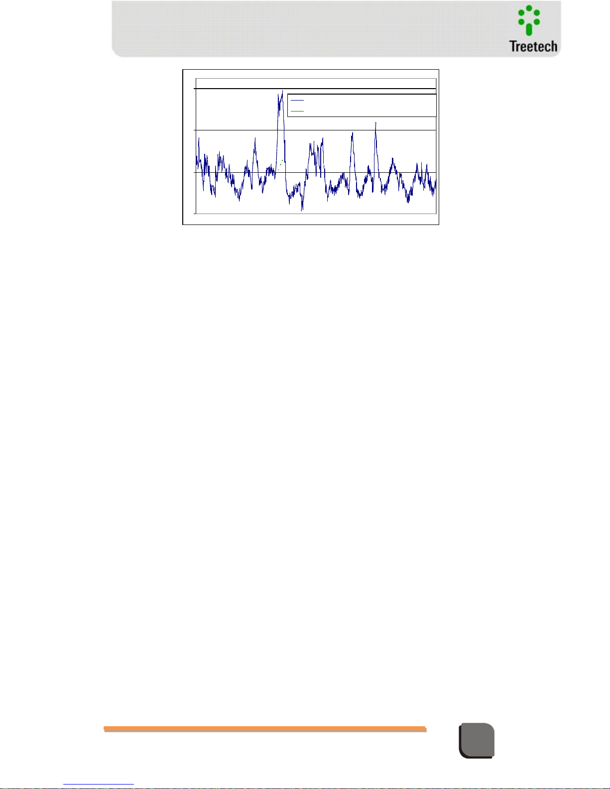
Under normal operating conditions, the LTC is a small source of heat compared to the heat
generated by the losses of the transformer, in the way that oil temperature in the LTC tank is
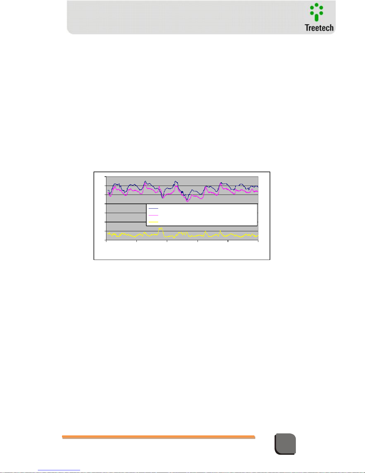
influenced principally by the transformer’s oil temperature. Illustration below, elaborated by
real measurements in the field, exemplifies this situation. In it we can observe, as well as the
individual transformer and tap changer temperatures, the difference between the LTC
temperatures minus the transformer’s, which is monitored to detect the faults mentioned
above.
Figure 2 – Temperature measurements of LTC, transformer and temperature differential
As the temperature differential is subject to the influence of external variables, such as the
action of forced cooling, rapid variations in atmospheric conditions and others, monitoring is
carried out by two distinct modes, illustrated in next figure, in order to increase diagnostic
efficiency and avoid false alarms:
Instantaneous Differential Monitoring - the Instantaneous Temperature Differential
monitoring triggers alarms with a rapid response in case there are large-scale faults,
even if they have short duration.
Monitoring of Filtered Differential - the Filtered Temperature Differential is obtained
by submitting the Instantaneous Differential to a low-pass filter with user adjustable
time-constant. Its monitoring enables the detection of the evolutionary trend of a
differential which indicates small permanent defects, over a longer period of
detection.
-10
0
10
20
30
40
50
60
28/8/2002
00:00:00
30/8/2002
00:00:00
1/9/2002
00:00:00
3/9/2002
00:00:00
5/9/2002
00:00:00
7/9/2002
00:00:00
TRANSFORMER OIL (ºC)
LTC OIL (ºC)
DIFFERENCE LTC-TRANSFORMER (ºC)
Page 18
Technical Manual – TM1/TM2 | MA-010| 2016-03-21 | Ver.: 6.30 18
Temperature Monitor
Figure 3 - Instantaneous and Filtered Temperature Differentials
The alarm settings to the monitoring of the Instantaneous and Filtered differentials can be
automatically determined by the Temperature Monitor, through a learning period about the
normal behavior of the LTC. The automatic alarm settings can be manually changed by user.
The duration of the learning period can be programmed by user. Typical value is one week.
During this period the Temperature Monitor will register the peak values for the Instantaneous
and Filtered Differentials. After that the alarm settings for both temperature differentials are
obtained by summing the peak values to a programmed tolerance margin.
If the measured temperature differentials, either Instantaneous or Filtered, exceed their
respective alarm settings the Temperature Monitor will trigger an alarm. This alarm is
indicated by a LED lamp on the device’s front panel and can operate the output contact A1-A2
on TM1 and/or TM2, provided these contacts are programmed by user in this way.
The measurements of transformer top oil temperature and load tap changer oil temperature
are performed by Pt100Ω@0ºC sensors, which are connected to the inputs available on
Temperature Monitors TM1 and TM2. TM1 has 2 temperature sensor inputs; at least one of
them must be used for transformer top oil temperature, the other one can be used for
redundant top oil measurement or for LTC, ambient or other temperatures. TM2 has 2
additional inputs available for LTC temperature, ambient temperature or others.
-8
-4
0
4
INSTANTANEOUS DIFFERENTIAL (ºC)
FILTERED DIFFERENTIAL (ºC)
Page 19
Technical Manual – TM1/TM2 | MA-010| 2016-03-21 | Ver.: 6.30 19
Temperature Monitor
3 Operation
All operations on the Temperature Monitors TM1 and TM2 are performed through the
keyboard on the front panel, without the need for any external selector switches. The
temperature of the oil, winding (or windings) and Load Tap Changer are shown on the displays,
and the alarm status, trips and forced cooling commands are indicated by the signal LEDs.
3.1 Initial Settings
During normal work mode, the Temperature Monitor will display the temperatures of the
oil and winding (or windings) connected to the equipment.
When the value programmed for an event is reached, the corresponding signal LED will light
up, and activate the output contact for this event.
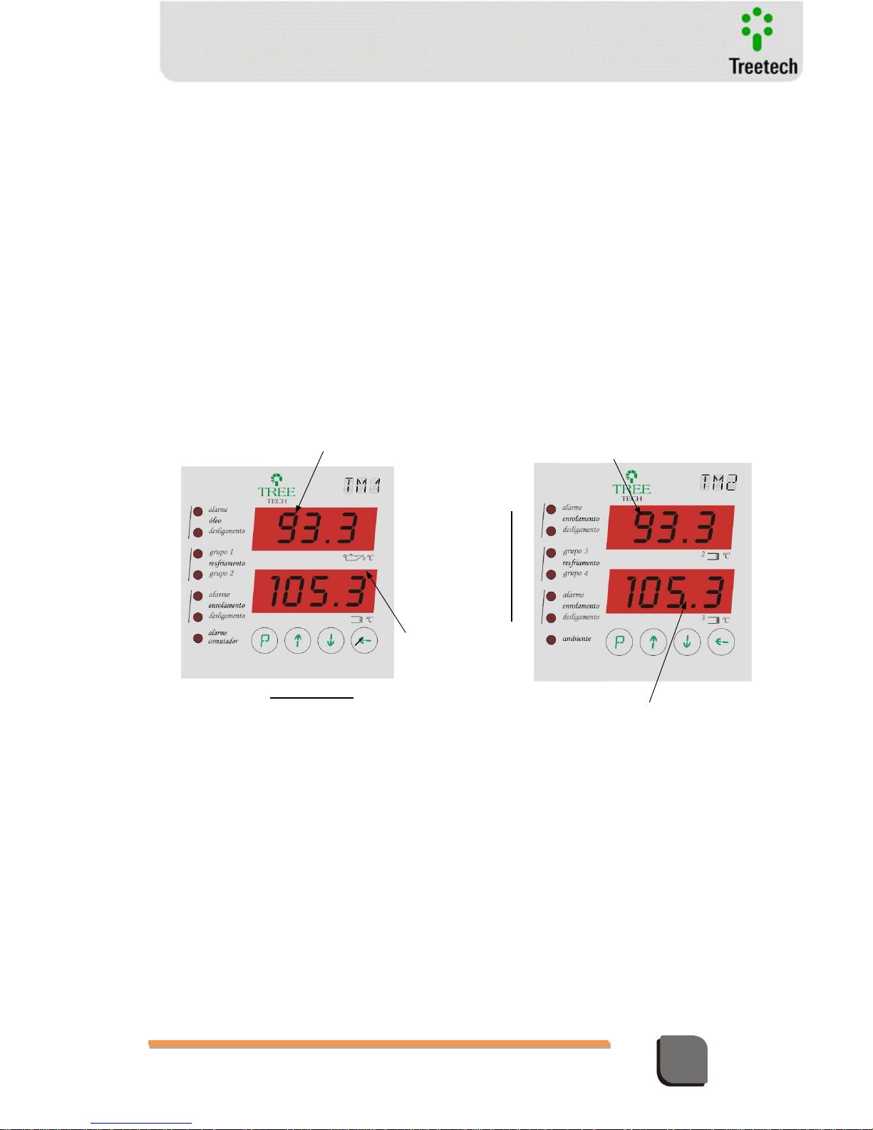
Winding 1
Temperature
Teclas de operação e
programação
Signaling
Leds
Oil
Temperature
Operation and
programming buttons
Winding 2
Temperature
Winding 3
Temperature
Figure 4 – Temperature Indications
Page 20
Technical Manual – TM1/TM2 | MA-010| 2016-03-21 | Ver.: 6.30 20
Temperature Monitor
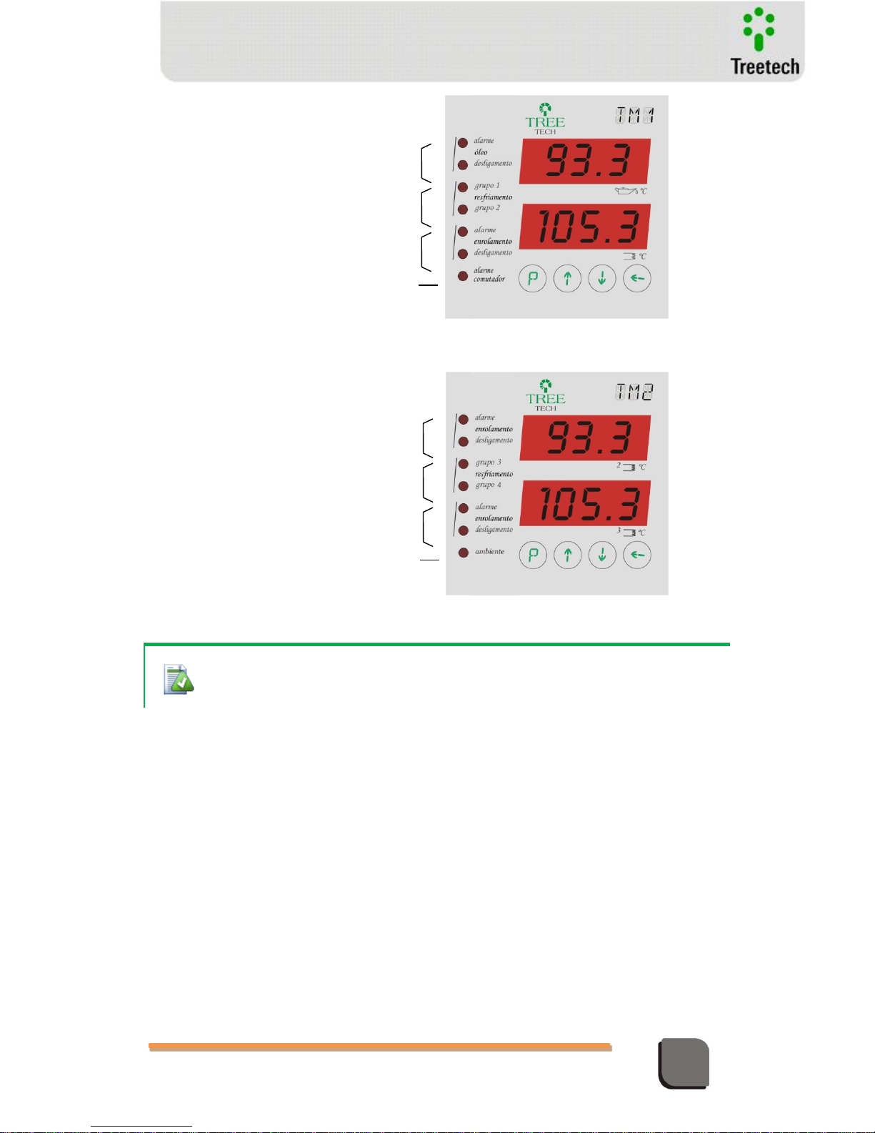
Figure 5 – Signaling LEDs on Temperature Monitor TM1
Figure 6 – Signaling LEDs on Temperature Monitor TM2
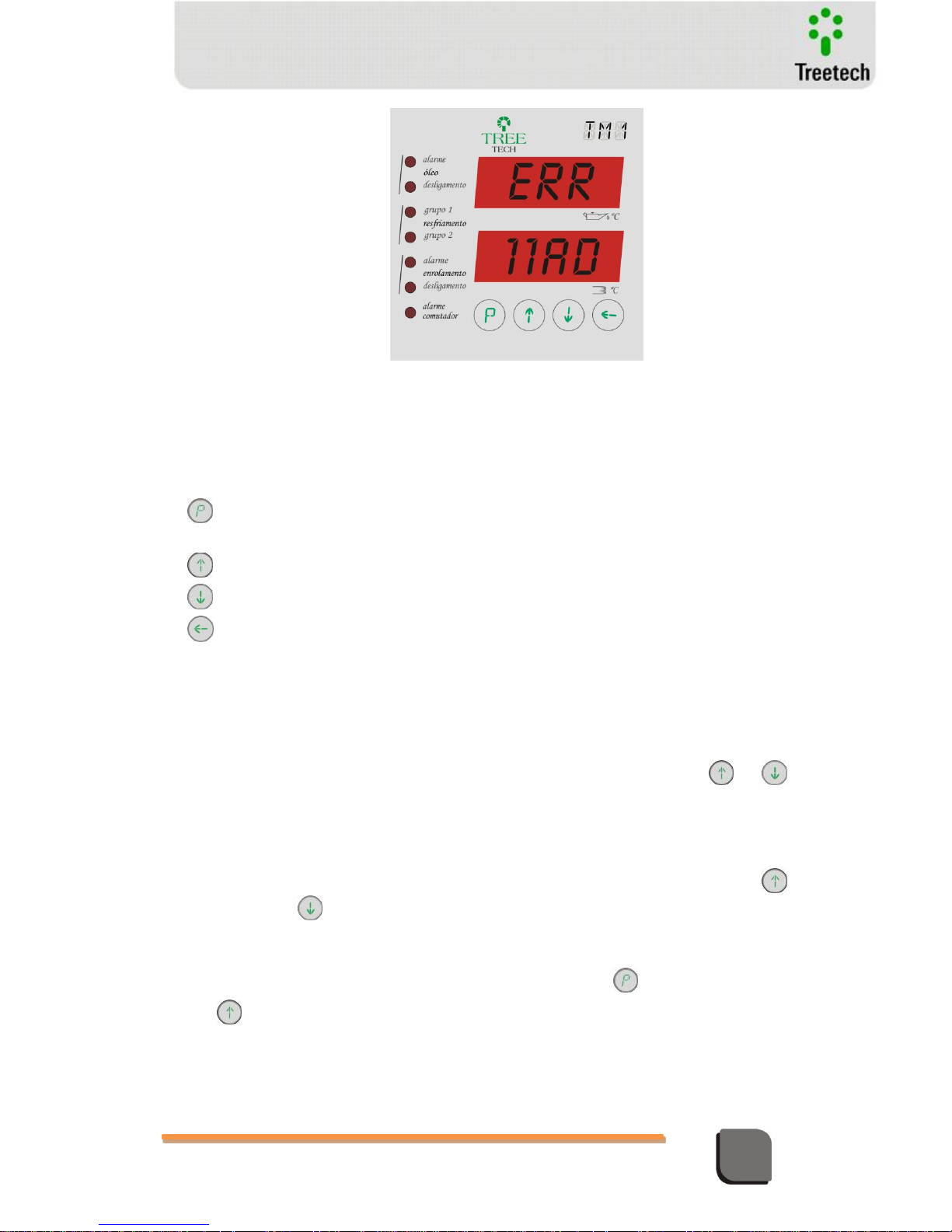
In case any abnormality occurs, the corresponding self-diagnostic code will be shown on the
displays.
If selected the PTA or PTB option in the DSP parameter of TM2, the LED indicating the presentation of
this temperature instead of winding temperature 3 - which is the standard indication - lights on the front
of TM2. This is the signal for the display mode of the lower display, DSP parameter TM2.
Oil Temperature
Alarm / Trip
Status of forced cooling groups 1
and 2
Load Tap Changer
Temperature Differential
Alarm (optional)
Winding 1 Temperature
Alarm / Trip
Winding 3 Temperature
Alarm / Trip
Winding 2 Temperature
Alarm / Trip
Forced Cooling Groups 1 and 2
(redundant) or 3 and 4 status
Indication mode of lower display: ambient
temperature (LED lit) or winding 3 temperature
(LED unlit)
Page 21
Technical Manual – TM1/TM2 | MA-010| 2016-03-21 | Ver.: 6.30 21
Temperature Monitor
3.2 Function of Keys
Programming Key: Access to programming menus and advance to next parameter in
submenus.
Up key: menu navigation and increment for programmed values.
Down key: menu navigation and decrement for programmed values.
Return key: returns to previous menu.
3.3 Consultation Screens
The Temperature Monitors makes available a set of different information items about the
transformer’s working situation. This information is accessed through the keys e
during normal work mode.
TM1 Consultation Screens
The device’s displays will exhibit the following information, sequentially by pressing the
key. By pressing the the data will be displayed in reverse to the order given below:
1) Maximum oil temperature (MAX)
- This is the maximum temperature reached by the oil during the period monitored.
- To reset this reading after consultation, press and hold the key and press the key
: the reading will match the current oil temperature.
2) Maximum temperature of winding 1 (MAX)
- Maximum temperature reached by winding 1 during the period monitored, shown on
the lower display.
Figure 7 – Self-diagnostic indications
Page 22
Technical Manual – TM1/TM2 | MA-010| 2016-03-21 | Ver.: 6.30 22
Temperature Monitor
- To reset this reading after consultation, press and hold the key and press the key
: the reading will match the current temperature for winding 1.
3) Final gradient (FTG)
- Displays what will be the difference between the temperatures of the oil and winding
1 after thermal stabilization, with the existing load situation remaining unchanged.
4) Percent load of the winding monitored (%)
- This is the load on the transformer, given as a percentage of the rated current for the
winding being monitored.
5) Current measured on the secondary of the CT (AMP)
- This is current on the secondary of the thermal image CT of the winding monitored,
given in Amperes.
6) Winding current in kA (kA)
- This is the current in the winding of the transformer whose temperature is being
monitored, given in kA.
7) Reading of the temperature sensor A connected to TM1 (PTA)
- This is the temperature being measured through temperature sensor “A”, given in °C.
8) Reading of the temperature sensor B connected to TM1 (PTB)
- The device will only display this information if it has been configured for two sensors
(see programming submenu configuration – CNF)
- This is the temperature being measured through temperature sensor “B”, given in °C,
which can be the oil, ambient or other temperature, as programmed on the
configuration submenu CNF.
9) Hour indication (HOU).
- Internal clock hour indication.
10) Minute indication (MIN).
- Internal clock minute indication.
11) Second indication (SEC).
- Internal clock second indication.
12) Day indication (DAY).
- Internal calendar day indication.
13) Month indication (MON).
- Internal calendar month indication.
14) Year indication (YAR).
- Internal calendar year indication.
15) Load Tap Changer temperature differential (LTC).
- The TM1 will only display this information if it has this optional feature. Press to
access the information regarding LTC minus transformer temperature differential.
- The device’s displays will exhibit the following information, sequentially by pressing
the key. By pressing the the data will be displayed in reverse to the order
given below:
15.1) TD1 - Instantaneous Temperature Differential of LTC 1.
15.2) TD2 - Instantaneous Temperature Differential of LTC 2.
15.3) TD3 - Instantaneous Temperature Differential of LTC 3.
Page 23
Technical Manual – TM1/TM2 | MA-010| 2016-03-21 | Ver.: 6.30 23
Temperature Monitor
15.4) FD1 - Filtered Temperature Differential of LTC 1.
15.5) FD2 - Filtered Temperature Differential of LTC 2.
15.6) FD3 - Filtered Temperature Differential of LTC 3.
15.7) AAS – Remaining time to finalize Automatic Alarm Settings for LTC
differentials, in hours. The value 0 (zero) indicates the learning process for automatic
settings is not in execution.
15.8) LTC / MAX – Maximum values reached by the temperature differentials in the
period. Press to enter the consultation. The device’s displays will exhibit the
following information, sequentially by pressing the key. By pressing the the
data will be displayed in reverse to the order given below:
TD1 / MAX – Maximum value reached by instantaneous differential of LTC 1.
TD2 / MAX – Maximum value reached by instantaneous differential of LTC 2.
TD3 / MAX – Maximum value reached by instantaneous differential of LTC 3.
FD1 / MAX – Maximum value reached by filtered differential of LTC 1.
FD2 / MAX – Maximum value reached by filtered differential of LTC 2.
FD3 / MAX – Maximum value reached by filtered differential of LTC 3.
LT1 / MAX – Maximum value reached by temperature of LTC 1.
LT2 / MAX – Maximum value reached by temperature of LTC 2.
LT3 / MAX – Maximum value reached by temperature of LTC 3.
15.9) LTC / MIN – Minimum values reached by the temperature differentials in the
period. Press to enter the consultation. The device’s displays will exhibit the
following information, sequentially by pressing the key. By pressing the the
data will be displayed in reverse to the order given below:
TD1 / MIN – Minimum value reached by instantaneous differential of LTC 1.
TD2 / MIN – Minimum value reached by instantaneous differential of LTC 2.
TD3 / MIN – Minimum value reached by instantaneous differential of LTC 3.
FD1 / MIN – Minimum value reached by filtered differential of LTC 1.
FD2 / MIN – Minimum value reached by filtered differential of LTC 2.
FD3 / MIN – Minimum value reached by filtered differential of LTC 3
Consultation Screen TM2
The following information will be exhibited on the device’s displays, sequentially by
pressing the key. If the key is pressed, the information will be displayed in reverse to
the order given below. Information regarding winding 2 and 3 is shown on the upper and lower
displays respectively.
1) Maximum temperature in winding 2 (MAX)
- Maximum temperature reached by winding 2, during the period monitored.
- To reset this reading after consultation, press and hold the key and press the key
: the reading will match the current temperature for winding 2.
Page 24
Technical Manual – TM1/TM2 | MA-010| 2016-03-21 | Ver.: 6.30 24
Temperature Monitor
2) Final gradient for winding 2 (FTG)
- Displays what will be the difference between the temperatures of the oil and winding
2 after thermal stabilization, with the existing load situation remaining unchanged.
3) Percent load of winding 2 (%)
- Load on winding 2, given as a percentage of the rated current for this winding.
4) Current measured on the secondary of the auxiliary CT 2 (AMP)
- Current measured on the secondary of the thermal image CT of the winding 2, given in
Amperes.
5) Current in winding 2 in kA (kA)
- Current in the winding 2 of the transformer whose temperature is being monitored,
given in kA.
6) Maximum temperature in winding 3 (MAX)
- Maximum temperature reached by winding 3, during the period monitored.
To reset this reading after consultation, press and hold the key and press the key :
the reading will match the current temperature for winding 3.
7) Final gradient for winding 3 (FTG)
- Displays what will be the difference between the temperatures of the oil and winding
3 after thermal stabilization, with the existing load situation remaining unchanged.
8) Percent load of winding 3 (%)
- Load on winding 3, given as a percentage of the rated current for this winding.
9) Current measured on the secondary of the auxiliary CT 3 (AMP)
- Current measured on the secondary of the thermal image CT of the winding 3, given in
Amperes.
10) Current in winding 3 in kA (kA)
- Current in the winding 3 of the transformer whose temperature is being monitored,
given in kA.
11) Reading of the temperature sensor A connected to TM2 (PTA)
- This is the temperature being measured through temperature sensor “A”, given in °C.
The device will only display this information if the input for RTD A on TM2 has been
configured for use.
12) Reading of the temperature sensor B connected to TM2 (PTB)
This is the temperature being measured through temperature sensor “B”, given in °C. The
device will only display this information if the input for RTD B on TM2 has been configured for
use
Toi check the Firmware version of the TM1/TM2, press e simultaneously. The complete
number of the firmware version will be shown at the display for 1 second.
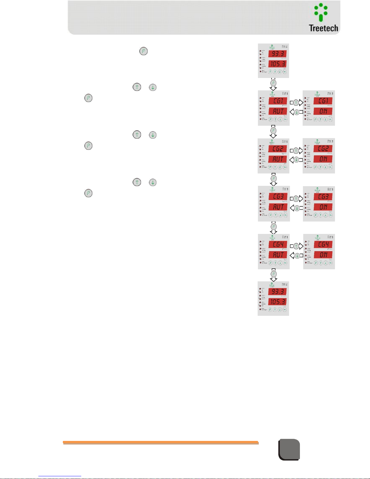
3.4 Commands
Through the keys , , and the forced cooling groups 1 to 4 can be manually
switched on or left under automatic control.
Page 25
Technical Manual – TM1/TM2 | MA-010| 2016-03-21 | Ver.: 6.30 25
Temperature Monitor
1) Push momentarily the key
TM1 shows the control screen of cooling group CG1
2) Push momentarily key or to command CG1 group
or to proceed to CG2 group
Cooling group 1 is selected either in manual (ON) or automatic
(AUT) mode.
3) Push momentarily key or to command CG2 group
or to proceed to CG3 group
Cooling group 2 is selected either in manual (ON) or automatic
(AUT) mode.
4) Push momentarily key or to command CG3 group
or to proceed to CG4 group
Cooling group 3 is selected either in manual (ON) or automatic
(AUT) mode.
5) Push momentarily the key or to command CG4 group or
to return to normal temperature indication.
Cooling group 4 is selected either in manual (ON) or automatic
(AUT) mode.
Page 26
Technical Manual – TM1/TM2 | MA-010| 2016-03-21 | Ver.: 6.30 26
Temperature Monitor
4 Project and Installation
4.1 System Topology
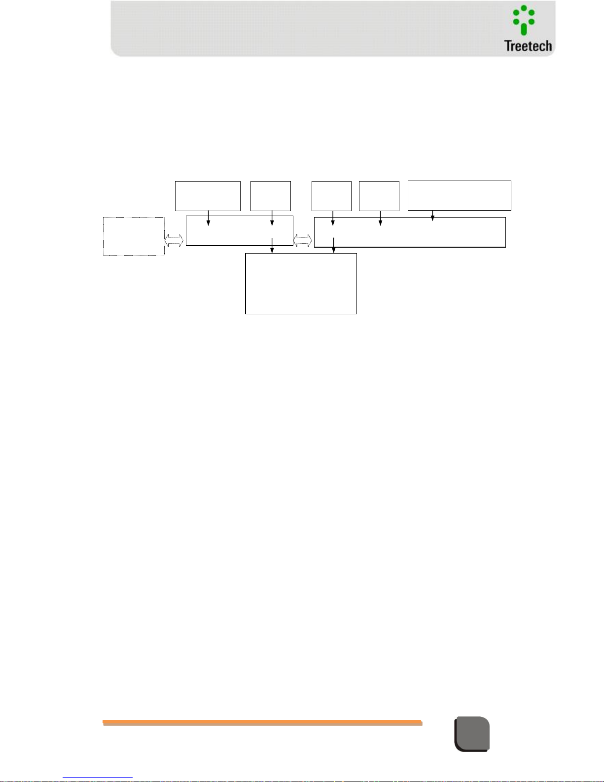
The Temperature Monitoring system is basically composed of:
The necessary items for the system are:
TM1 Temperature Monitor
RTD Sensor (number ad type according to the desired configuration)
TM2 Temperature Monitor (only if monitoring for more than one winding or
measurement of more than 2 RTD sensors are needed)
Current transformers (Transformer bushing CT)
2-way shielded twisted pair for serial communication
3 or 4 way shielded cable (according to the connection option adopted) for the RTD
connection
Outdoor installation box (optional)
External clip-on CTs (optional use).
4.2 Inputs and Outputs
The following inputs and outputs are available on the TM1 and TM2 Temperature Monitors:
TM1 Temperature Monitor
Data
Acquisition
System
TM2 Temperature Monitor
RTDs
(Oil and others)
CT
(Wind.1)
CT
(Wind.2)
CT
(Wind.3)
- cooling command
- alarms
- trips
- remote readings
- self-diagnosis
RTDs
(LTCs and Others)
Figure 8 – Block Diagram
Page 27
Technical Manual – TM1/TM2 | MA-010| 2016-03-21 | Ver.: 6.30 27
Temperature Monitor
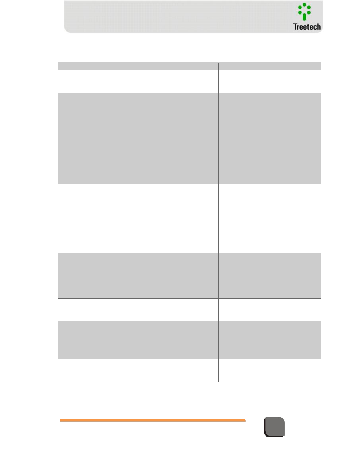
Table 3 – TM1/TM2 Inputs
TERMINALS
INPUTS
TM1
TM2
1) Auxiliary power feed and ground:
Universal power feed input
(38 ~ 265 Vdc/Vac, @ 8W, 50/60Hz).
13 – ground
14 – dc/ac
15 – dc/ac
13 – ground
14 – dc/ac
15 – dc/ac
2) RTD input connection on TM1:
Allows RTD sensors to be connected using five distinct
configurations (see connection option diagrams):
two 3-wire RTDs in redundant configuration to measure top oil
temperature;
one 4-wire RTD to measure top oil temperature;
one 3-wire RTD at input A to measure top oil temperature;
one 3-wire RTD at input B to measure top oil temperature.
one 3-wire RTD at input A to measure top oil temperature and one
3-wire RTD at input B to measure another temperature (for
instance, ambient or LTC);
22, 23, 24, A5 and A6
3) RTD input connection on TM2:
Allows connection of RTD sensors using four distinct configurations
(see connection option diagrams) to measure additional temperatures,
for instance ambient or LTC:
one 4-wire RTD;
one 3-wire RTD at input A;
one 3-wire RTD at input B;
two 3-wire RTDs at inputs A and B.
-----
22, 23, 24, A5 and
A6
4) Port RS485 TM2:
Connection to complementary Temperature Monitor TM2 via shielded
twisted pair cable.
When the option for protocol DNP3.0 is used with function IRIG-B,
which synchronizes equipment clock via GPS, this port is used, so the
TM 2 cannot be used.
16 ( + )
17 ( - )
-----
5) Port RS485 TM1:
Connection to Temperature Monitor TM1 via shielded twisted pair
cable.
-----
16 ( + )
17 ( - )
6) Port RS485 / RS232 - Scada:
Connection with data capture system, protocol MODBUS-RTU
(standard) or DNP3.0 (optional). The selection of communication port
RS485 or RS232 is defined on device’s programming.
A7 ( + )
A8 ( - )
or
Connector DB9 (rear
panel)
-----
7) Input for CT:
Input for direct measurement of the secondary of the bushing CT for
thermal imaging or for connection of external clip-on CT.
25 and 26 (CT 1)
25 and 26 (CT 3)
27 and 28 (CT 2)
Page 28
Technical Manual – TM1/TM2 | MA-010| 2016-03-21 | Ver.: 6.30 28
Temperature Monitor
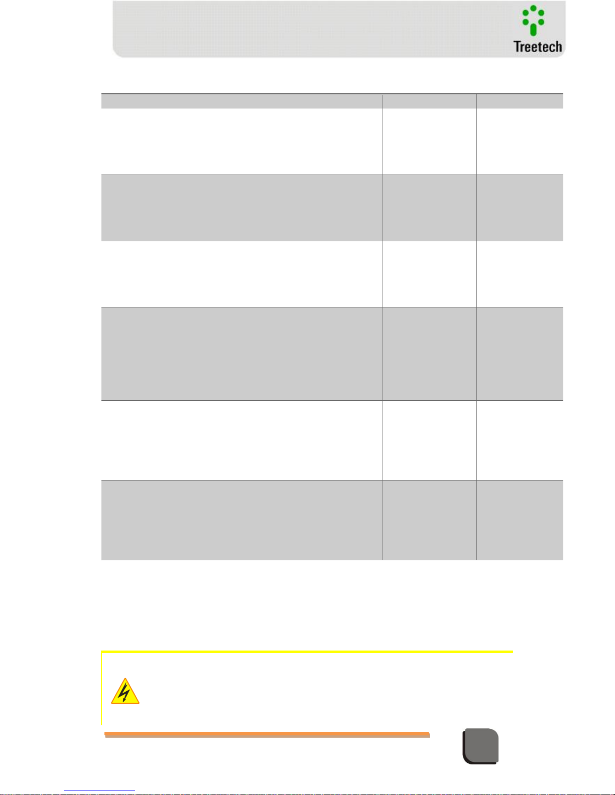
Table 4 - TM1/TM2 outputs
TERMINALS
OUTPUTS
TM1
TM2
1) Saídas em loop de corrente:
Duas saídas com positivo comum para indicação remota das
temperaturas medidas, programáveis pelo usuário. Padrão de saída
selecionado na parametrização (0...1, 0...5, 0...10, 0...20 ou 4...20 mA).
18(+) Common
19( - )
20(+) Common
21( - )
18(+) Common
19( - )
20(+) Common
21( - )
2) Alarm relay:
Two independent contacts, potential free (NO), triggers alarm due to
high temperature of transformer. Pending request, these contacts can
be supplied normal closed (NC).
1 OIL
2
9 WIND
10
1 OIL
2
9 WIND
10
3) Trip relay:
Two independent contacts, potential free (NO), for the transformer
protection circuit. These contacts can be programmed to act with
timers of up to 20 minutes.
3 OIL
4
11 WIND
12
3 OIL
4
11 WIND
12
4) Forced cooling command relays:
Two independent dry contacts (NC) in each Temperature Monitor to
command up to 4 transformers’ forced cooling groups (using TM1 and
TM2). When the Temperature Monitors are energized, these contacts
change state, returning to the rest position to turn on forced cooling.
Pending request, these contacts can be supplied normally open (NO).
5 C.G.1
6
7 C.G. 2
8
5 C.G 3 ou
6 C.G. 1
7 C.G. 4 ou
8 C.G..2
5) Self-diagnosis relay:
Potential free contact (NC), signals failure in power feed, internal or
system failure. When the Temperature Monitor is energized, these
contacts change state, returning to the rest position in the event of a
failure. Pending request, these contacts can be supplied normally open
(NO).
A3 and A4
A3 and A4
6) Trip or LTC differential signal relay:
Potential free contact (NO), programmable to signal alarm by LTC
temperature differentials or trip of transformer - closes
instantaneously when trip temperature is reached, signaling trip
underway, in case protection contacts are timer controlled. Pending
request, these contacts can be supplied normally closed (NC).
A1 and A2
A1 and A2
4.3 Project and Installation
Some special care must be followed for TM1 and TM2 project and installation, as described
below.
A circuit breaker must be used immediately before the power supply input (Universal supply - 38 ~ 265
Vdc/Vac, <5 W, 50/60 Hz), which corresponds to the pins 14 and 15 of TM1/TM2. This circuit breaker
must have a number of poles corresponding to the number of phases used in the supply – being that
the poles must interrupt only the phases, and never the neutral or ground – and provide the conductors
that supply the equipment with thermal and electrical protection.
The circuit breaker must be near the equipment and easily maneuverable by the operator. It must also
Page 29
Technical Manual – TM1/TM2 | MA-010| 2016-03-21 | Ver.: 6.30 29
Temperature Monitor
have an indelible identification showing that it is the electrical connection device of the TM1/TM2.
The following circuit breaker specification is recommended, when exclusively for the TM1/TM2:
AC/DC Supply, Phase-Neutral: Single-pole circuit breaker, 1 A ≤ In ≤ 2 A, curve B or C, NBR/IEC
60947-2, NBR/IEC 60898 or IEEE 1015-2006 standards;
AC/DC Supply, Phase-Phase: Two-pole circuit breaker, 1 A ≤ In ≤ 2 A, curve B or C, NBR/IEC
60947-2, NBR/IEC 60898 or IEEE 1015-2006 standards.
The minimum insulation for the circuits connected to the TM1/TM2 is 300 Vrms for auxiliary equipment
and transducers, like Pt-100 and for equipment with own supply with 50 V
rms
.
The minimum insulation is 1.7 kVrms for equipment supplied with up to 300 Vrms, according to IEC EN
61010-1.
These values are related to intrinsic insulation of the devices connected to the TM1/TM2. Cases in
which this value does not apply to equipment or devices connected to the TM1/TM2 will be explicitly
informed in this manual.
RTD Temperature Sensors
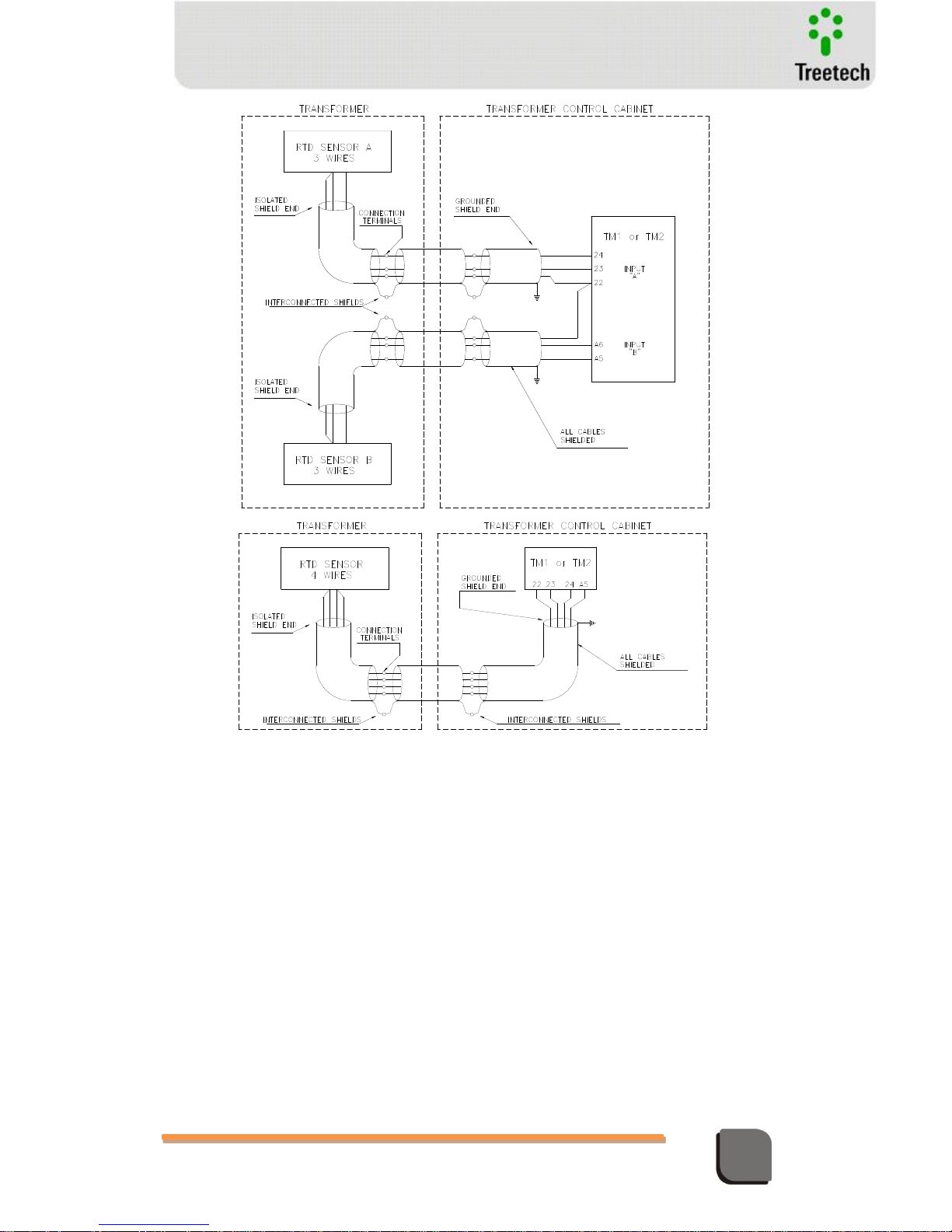
The RTD temperature sensors (oil, ambient, load tap changers or others) must be connected to
the Temperature Monitors TM1 and TM2 by way of a shielded cable, without interruption of
the shield, which must be grounded only at the end connected to the Temperature Monitor, as
close to it as possible. In case intermediate terminal blocks are needed for the RTD sensors,
the cable shields should also be connected through the terminal blocks, thus keeping it free of
interruption. The unshielded stretch of cable due to the connection should be as short as
possible.
The maximum resistance for each one of the used ways at the TM1/TM2’s interconnection
cable with the Pt-100 is 3Ω. Therefore, 6Ω for the round trip to and from the Pt-100 sensor of the
TM1 / TM2.
Considering the maximum allowed resistance in the connection between the Pt-100 and the
TM1 / TM2, we have that for a copper cable with 1.5 mm² gauge, the Pt-100 can be installed at a
maximum distance of 265 m from the TM1 / TM2. Other values are possible with the correct
sizing of cable. If you need support for cable sizing, please contact the Treetech Application
Engineering.
Page 30
Technical Manual – TM1/TM2 | MA-010| 2016-03-21 | Ver.: 6.30 30
Temperature Monitor
Serial Communication Ports RS485
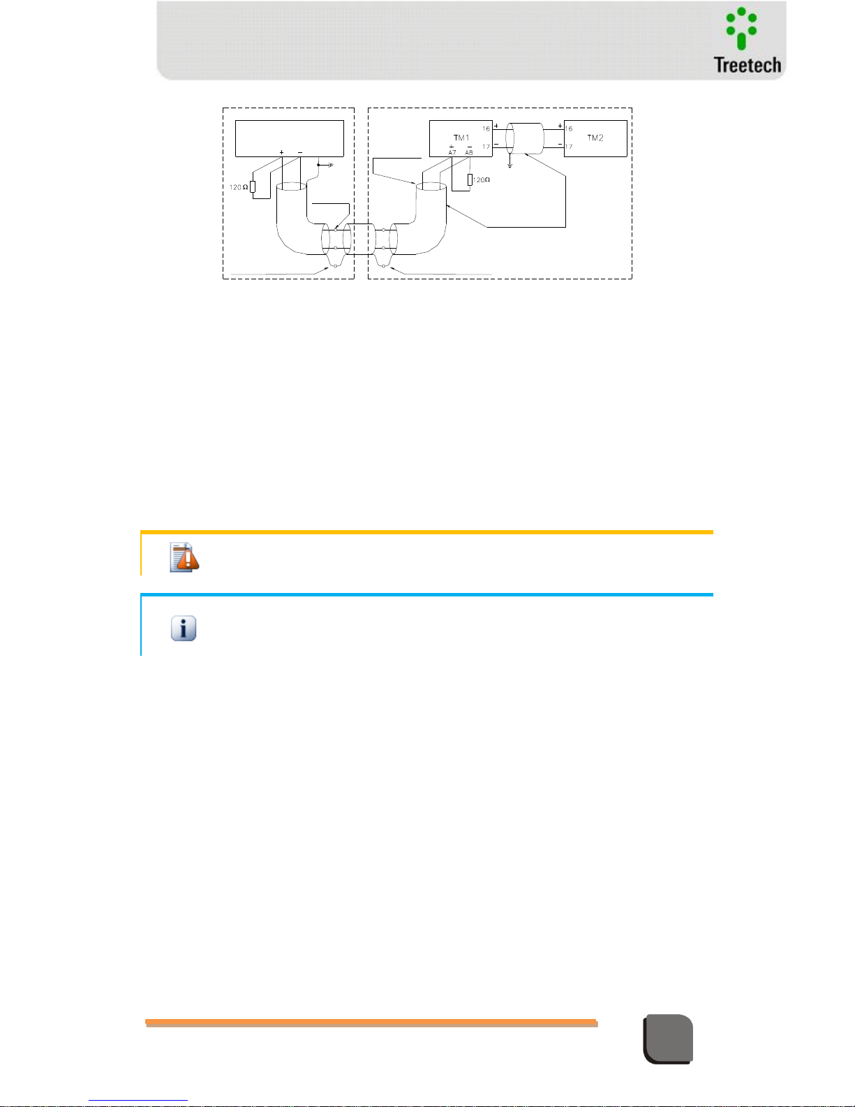
Serial communication (RS485) between the Temperature Monitors TM1 and TM2 must be
linked by way of a shielded twisted pair cable, keeping the shield uninterrupted all the way to
its specific input at the devices, with only one of the ends being grounded. The same cares
must be taken in connecting the serial connection (RS485) of the TM1 Temperature Monitor to
a Data Acquisition system, bearing in mind that the maximum admissible distance for this type
of communication is 1300 meters.
In case intermediate terminal blocks are needed for the serial RS485 communication link, the
cable shield should also be passed by the terminal blocks, thus keeping it free of interruption.
The unshielded stretch of cable due to the connection should be as short as possible.
Figure 9 – Detail Shield Connection of RTD Sensor
Page 31
Technical Manual – TM1/TM2 | MA-010| 2016-03-21 | Ver.: 6.30 31
Temperature Monitor
CONTROL ROOM
TRANSFORMER PANEL
CONNECTION
TERMINAL
DATA ACQUISITION
SYSTEM
ISOLATED
SHIELD
INTERLINKED SHIELD
INTERLINKED SHIELD
ALL CABLES
SHIELD
TWISTED PAIR
Figure 10 – Shield connection of serial communication
Analogic Outputs
The analogic signal circuit - mA output - should be connected through a shielded twisted pair
cable, keeping the mesh without interruption until his termination on the specific input of the
equipment grounding only one end.
In case intermediate terminal blocks are needed for the mA outputs communication link, the
cable shield should also be passed by the terminal blocks, thus keeping it free of interruption.
The unshielded stretch of cable due to the connection should be as short as possible.
The two outputs relating to pins 18 and 20 are interconnected, resulting in a positive common.
The use of unsuitable cables for RS-485 communication and mA output can compromise the
performance of TM1 / TM2.
Always use the recommended cables.
Current Transformers
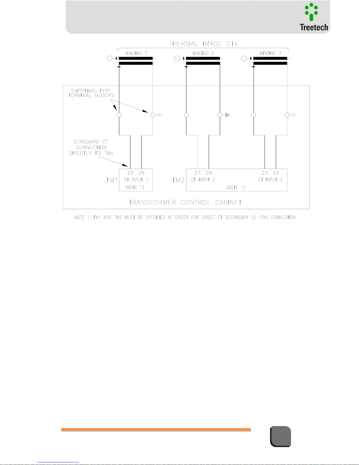
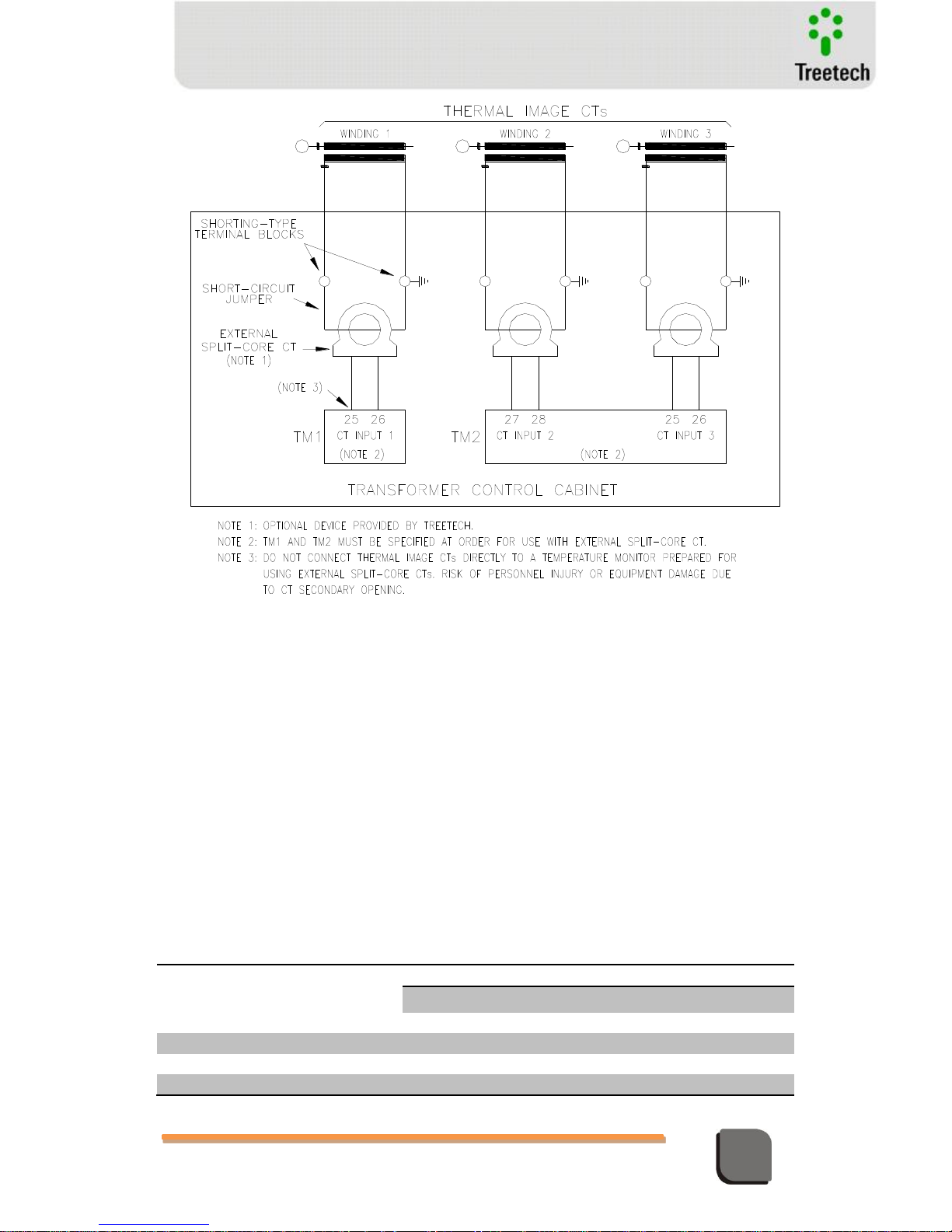
Current transformer connections must be performed according to the model of
Temperature Monitor specified:
For direct connection of thermal image CT secondaries (0-10A) to the Temperature
Monitors; or
For connection using external clip-on (split-core) CTs.
In both cases, due care must be taken to avoid opening thermal image CT secondaries,
making sure that the transformer is de-energized or the CT terminal blocks are short-circuited
and grounded during system instalation or maintenance.
Page 32
Technical Manual – TM1/TM2 | MA-010| 2016-03-21 | Ver.: 6.30 32
Temperature Monitor
Figure 11 – Connection details of current transformers directly Temperature Monitors
Page 33
Technical Manual – TM1/TM2 | MA-010| 2016-03-21 | Ver.: 6.30 33
Temperature Monitor
Figure 12 – Connection details of current transformers to Temperature Monitors prepared
for external cilip-on CTs
Forced Cooling Control
Each Temperature Monitor TM1 and TM2 has two independent and free of potential NC
contacts, to command from 1 to 4 forced cooling groups, as defined by the user. Groups 1 and
2 are controlled by TM1 contacts 5-6 and 7-8, and groups 3 and 4 by TM2 contacts 5-6 and 7-8,
respectively. When energizing Temperature Monitors, these contacts change their statuses
and return to home position to activate cooling. Under request, they can be supplied normally
open (NO). Preset forced cooling operation is divided in 4 Cooling Stages. At each Stage, its
operation temperature (and load percentage for operation, in case the optional pre-cooling is
available) and the Cooling Groups enrolled and available for use in this Stage are preset. Table
below shows an example of Cooling Stage presets:
Cooling
Stage
Activation
Temperature
Cooling Groups
CG 1
CG 2
CG 3
CG 4
CS1
FC1 = 60ºC
YES
YES
NO
NO
CS2
FC2 = 65ºC
YES
YES
NO
NO
CS3
FC3 = 70ºC
NO
NO
YES
YES
CS4
FC4 = 75ºC
NO
NO
YES
YES
Page 34

Technical Manual – TM1/TM2 | MA-010| 2016-03-21 | Ver.: 6.30 34
Temperature Monitor
When a given Stage activation temperature is reached, only one of its enrolled Cooling Groups
will be activated (the groups enrolled in that Stage are those selected as "YES".) The selection
of which Group will be activated is based on Groups' working times: the one showing the
lowest working time will be chosen. Similarly, whenever the temperature falls below the Stage
deactivation value, only one among those Cooling Groups which are on and enrolled in that
Group will be turned off. The selection of which Group will be deactivated is based on Groups'
working times: the one showing the highest working time will be chosen. So that there is a
tendency the Cooling Groups have equal working times, thus preventing an excessive wear and
tear of a group in comparison to the others.
Following are shown some examples of the different possible applications for the TM1/TM2
forced cooling control with the respective configurations
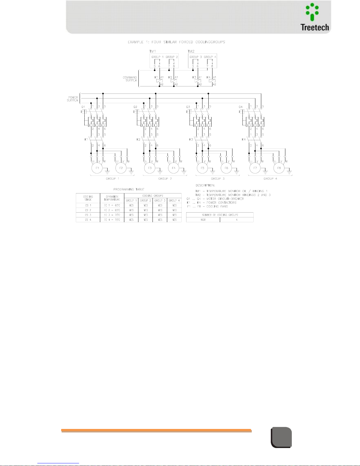
Example 1 – Four equal Cooling Groups with stepped activation temperatures
In this example, as the 4 groups are equal, it is desirable the group activation is shifted as the
measured temperature raises. Otherwise, in case the groups' activation sequence is fixed, the
activated groups with lower temperature could show a significantly higher wear and tear in
comparison to others. In order to achieve total shift among the 4 groups, all of them are
enrolled (and selected as “YES”) in all Cooling Stages.
As example, let's say groups 1 to 4 have the following accumulated operation times: 1034,
1056, 993, and 1042 hours, respectively. When winding temperature raises and reaches 60ºC,
among the Groups enrolled in Stage 1 (Groups 1, 2, 3 and 4) the one having the lowest
operation time will be activated, Group 3 in this case. When winding temperature reaches
65ºC, among the Groups enrolled in Stage 2 and which are not yet in operation, the one having
the lowest operation time will be activated, Group 1 in this case. Similarly, at 70ºC Group 4 will
be activated and at 75ºC, Group 2.
Continuing from the previous example, let's say that after some time working with
temperature above 75ºC, the accumulated operation times for groups from 1 to 4 are: 1042,
1060, 1003, and 1048 hours, respectively. Assuming yet a hysteresis adjustment of 1ºC, when
winding temperature falls below 74ºC, among those Groups enrolled in Stage 4 and which are
in operation, the one having the higher operation time will be deactivated, Group 2 in this
case. When winding temperature falls below 69ºC, among the Groups enrolled in Stage 3 and
which are still in operation , the one having the highest operation time will be activated, Group
4 in this case. Similarly, below 64ºC Group 1 will be deactivated and below 59ºC, Group 3.
Page 35
Technical Manual – TM1/TM2 | MA-010| 2016-03-21 | Ver.: 6.30 35
Temperature Monitor
Figure 13 – Command of 4 equal forced cooling groups shifting the operation of groups
Example 2 – One Cooling Group with Oil Pumps and Three equal Cooling Groups with Fans
having stepped activation temperatures
In this example, as Group 1 is different from Groups 2 to 4, which in their turn are equal to
each other, Group 1 should not be shifted to other groups, and it is desirable that Groups 2, 3
and 4 are shifted. For this purpose, only Group 1 is enrolled (selected as “YES”) in Cooling Stage
1, and in order to groups 2, 3 and 4 are shifted, they are enrolled in Cooling Stages 2, 3 and 4.
As example, let's say groups 1 to 4 have the following accumulated operation times: 2011,
1245, 1191, and 1187 hours, respectively. When winding temperature raises and reaches 60ºC,
Group 1, which is the only one enrolled in Stage 1, will be mandatorily activated. When
winding temperature reaches 65ºC, among the Groups enrolled in Stage 2 (Groups 2, 3 and
4), the one having the lowest operation time will be activated, Group 4 in this case. When
winding temperature reaches 70ºC, among the Groups enrolled in Stage 3 and which are not
yet in operation , the one having the lowest operation time will be activated, Group 3 in this
case. Similarly, at 75ºC, Group 2 will be activated.
Continuing from the previous example, let's say that after some time working with
temperature above 75ºC, the accumulated operation times for groups from 1 to 4 are: 2022,
1249, 1196, and 1197 hours, respectively. Assuming yet a hysteresis adjustment of 1ºC, when
winding temperature fall below 74ºC, among those Groups enrolled in Stage 4 and which are
Page 36
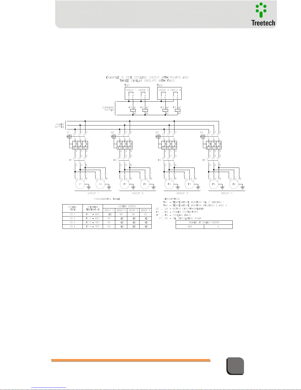
Technical Manual – TM1/TM2 | MA-010| 2016-03-21 | Ver.: 6.30 36
Temperature Monitor
in operation, the one having the higher operation time will be deactivated, Group 2 in this
case. When winding temperature falls below 69ºC, among the Groups enrolled in Stage 3 and
which are still in operation, the one having the highest operation time will be activated, Group
4 in this case. Similarly, below 64ºC Group 3 will be deactivated and below 59ºC, Group 1,
which is the only one enrolled in Stage 1, will be deactivated.
Figure 14 – Command of 1 forced cooling group with pumps and 3 equal groups with fans
shifting the operation of fan grops
Example 3 – Two equal Cooling Groups with pumps and two equal Groups with fans
having stepped activation temperatures
In this example, Groups 1 and 2 are equal to each other and different from Groups 3 and 4,
which in their turn are equal to each other. So that no shift of Groups 1 and 2 with Groups 3
and 4 is required, however it is desirable a shift between Groups 1 and 2 and another
independent shift between Groups 3 and 4. For this purpose, only Groups 1 and 2 are enrolled
(selected as “YES”) in Cooling Stages 1 and 2, and Groups 3 and 4 are enrolled in Cooling Stages
3 and 4.
As example, let's say groups 1 to 4 have the following accumulated operation times: 1803,
1798, 1501, and 1509 hours, respectively. When winding temperature raises and reaches 60ºC,
among the Groups enrolled in Stage 1 (Groups 1 and 2) the one having the lowest operation
Page 37
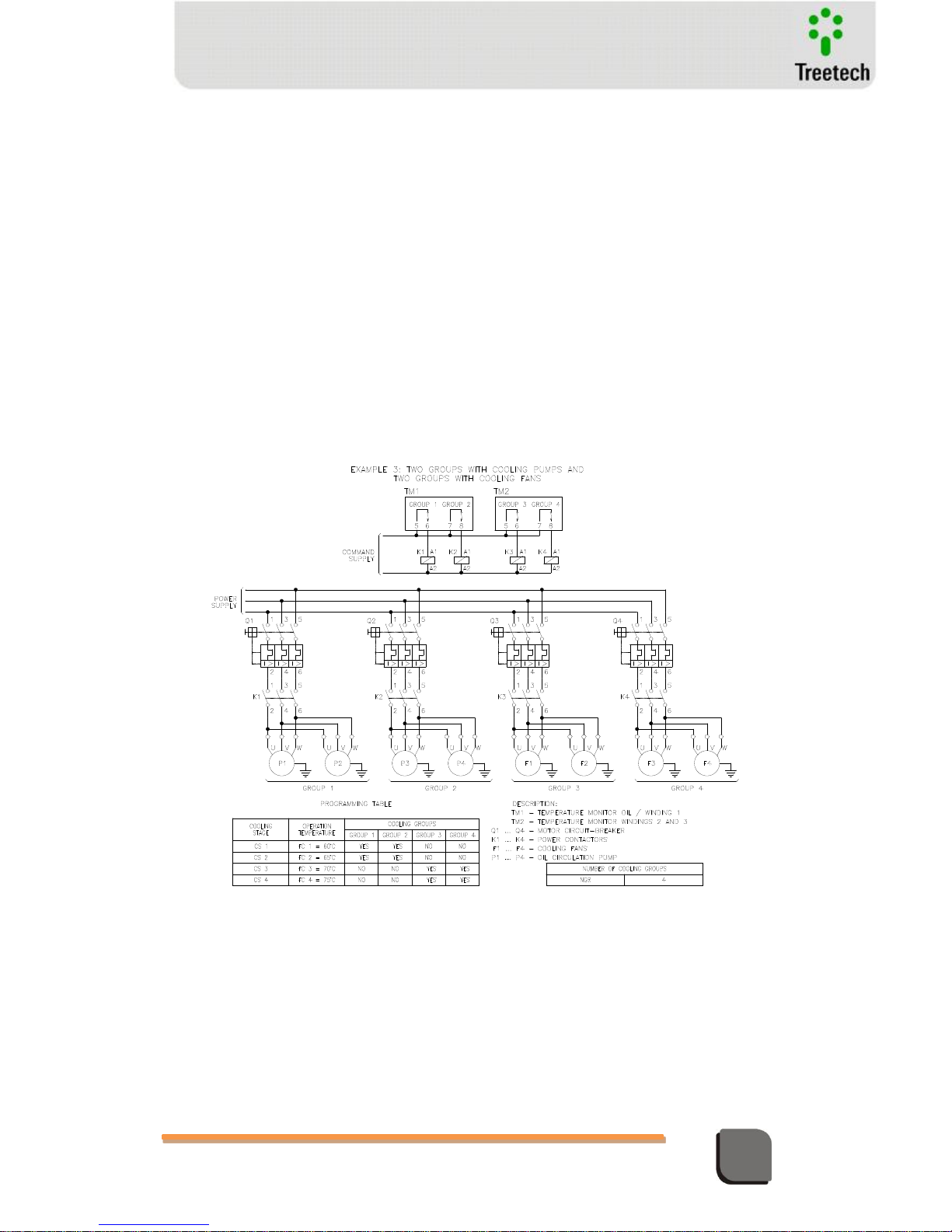
Technical Manual – TM1/TM2 | MA-010| 2016-03-21 | Ver.: 6.30 37
Temperature Monitor
time will be activated, Group 2 in this case. When winding temperature reaches 65ºC, among
the Groups enrolled in Stage 2 and which are not yet in operation, the one having the lowest
operation time will be activated, Group 1 in this case. When winding temperature reaches
70ºC, among the Groups enrolled in Stage 3 and which are not yet in operation, the one having
the lowest operation time will be activated, Group 3 in this case. Similarly, at 75ºC, Group 4
will be activated.
Continuing from the previous example, let's say that after some time working with
temperature above 75ºC, the accumulated operation times for groups from 1 to 4 are: 1809,
1810, 1505, and 1512 hours, respectively. Assuming yet a hysteresis adjustment of 1ºC, when
winding temperature falls below 74ºC, among those Groups enrolled in Stage 4 and which are
in operation, the one having the higher operation time will be deactivated, Group 4 in this
case. When winding temperature falls below 69ºC, among the Groups enrolled in Stage 3 and
which are still in operation, the one having the highest operation time will be deactivated,
Group 3 in this case. Similarly, below 64ºC Group 1 will be deactivated and below 59ºC, Group
2.
Figure 15 – Comman of 2 equal forced cooling groups with pumps and 2 equal groups with
fans, with independente shifting for the operation of the pump groups and the fan groups
Example 4 – Four equal Cooling Groups, with motor start timer
In this example, the Cooling Stages have to be activated in only 2 different steps, 60ºC and
65ºC. However, in order to reduce the current peak due to motors ignition, the fans were
divided in 4 equal cooling groups, so that when any of the temperature steps is reached one
group is promptly activated, and after 10 seconds, another one is activated.
Page 38

Technical Manual – TM1/TM2 | MA-010| 2016-03-21 | Ver.: 6.30 38
Temperature Monitor
In order to shift fans activation, Cooling Stages 1 and 2 are programmed with the same
activation temperature, however only Groups 1 and 2 are enrolled (selected as “YES”) in Stage
1 and Groups 3 and 4 are enrolled in Stage 2. Similarly, Stages 3 and 4 are programmed with
the same activation temperature, only Groups 1 and 2 are enrolled in Stage 3, and Groups 3
and 4 are enrolled in Stage 4.
As an example, let's say that groups 1 to 4 have the following accumulated operation times:
500, 503, 500, and 503 hours, respectively. When winding temperature raises and reaches
60ºC, among the Groups enrolled in Stage 1 (Groups 1 and 2) the one having the lowest
operation time will be activated - Group 1 in this case - and after 10 seconds, among the
Groups enrolled in Stage 2 (Groups 3 and 4), the one having the lowest operation time will be
activated, Group 3 in this case. When winding temperature reaches 65ºC, among the Groups
enrolled in Stage 3 and with are not in operation, the one having the lowest operation time
will be activated - Group 2 in this case - and after 10 seconds, among the Groups enrolled in
Stage 4 (Groups 3 and 4) and which are not in operation, the one having the lowest operation
time will be activated, Group 4 in this case.
Continuing from the previous example, let's say that after some time the temperature falls
below 59ºC and all cooling groups are deactivated, now being the accumulated operation
times for groups from 1 to 4: 509, 508, 509, and 508 hours, respectively. When winding
temperature raises and reaches 60ºC, among the Groups enrolled in Stage 1 (Groups 1 and 2)
the one having the lowest operation time will be activated - Group 2 in this case - and after 10
seconds, among the Groups enrolled in Stage 2 (Groups 3 and 4), the one having the lowest
operation time will be activated, Group 4 in this case. When winding temperature reaches
65ºC, among the Groups enrolled in Stage 3 and with are not in operation, the one having the
lowest operation time will be activated - Group 1 in this case - and after 10 seconds, among
the Groups enrolled in Stage 4 (Groups 3 and 4) and which are not yet in operation, the one
having the lowest operation time will be activated, Group 3 in this case.
Page 39
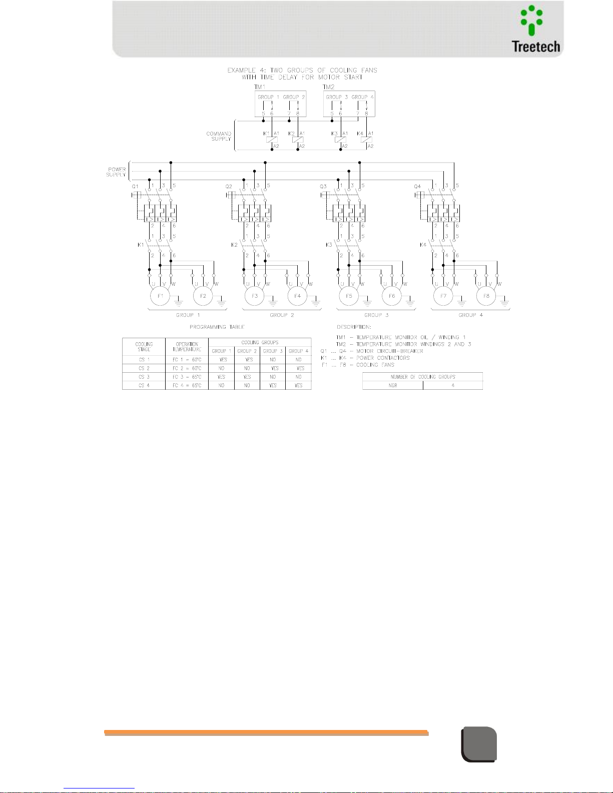
Technical Manual – TM1/TM2 | MA-010| 2016-03-21 | Ver.: 6.30 39
Temperature Monitor
Figure 16 – Command of 4 equal forced cooling groups in 2 temperature stages, with timer
for motors start and shifting the groups
In transformers with only two cooling groups, TM2 contacts are used to control redundantly
groups 1 and 2 and should be connected in parallel with the contacts of TM1.
Example 5 – Two equal Cooling Groups, with redundancy of cooling control
In this example, the Cooling Stages have to be activated in only 2 different steps, 60ºC and
65ºC. However, as the motors ignition timer is not required, only 2 Cooling Groups are used,
and TM2 contacts are used to redundantly control Groups 1 and 2, which have to be
connected in parallel with TM1 contacts. In order to shift the 2 groups activation, both are
enrolled (selected as “YES”) in two Cooling Stages.
As an example, let's say that groups 1 and 2 have the following accumulated operation times:
645 and 648 hours, respectively. When winding temperature raises and reaches 60ºC, among
the Groups enrolled in Stage 1 (Groups 1 and 2) the one having the lowest operation time will
be activated, Group 1 in this case. When winding temperature reaches 65ºC, among the
Groups enrolled in Stage 2 and which are not yet in operation, the one having the lowest
operation time will be activated, Group 2 in this case.
Continuing from the previous example, let's say that after some time the temperature falls
below 59ºC and all cooling groups are deactivated, now being the accumulated operation
Page 40
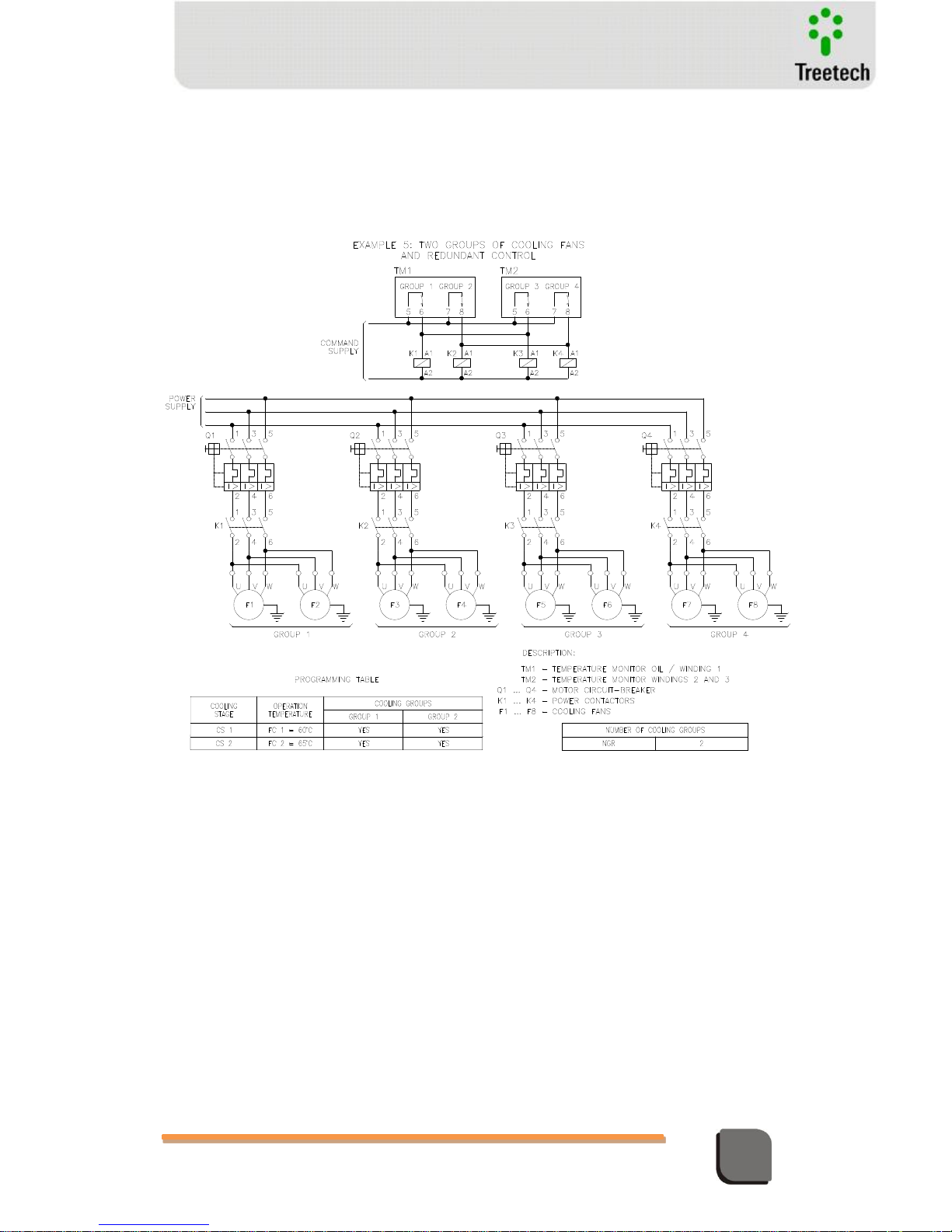
Technical Manual – TM1/TM2 | MA-010| 2016-03-21 | Ver.: 6.30 40
Temperature Monitor
times for groups 1 and 2: 651 and 650 hours, respectively. When winding temperature raises
and reaches 60ºC, among the Groups enrolled in Stage 1 (Groups 1 and 2) the one having the
lowest operation time will be activated, Group 2 in this case. When winding temperature
reaches 65ºC, among the Groups enrolled in Stage 2 and which are not yet in operation, the
one having the lowest operation time will be activated, Group 1 in this case.
Figure 17 – Command of 2 equal forced cooling groups with command redundancy
Page 41
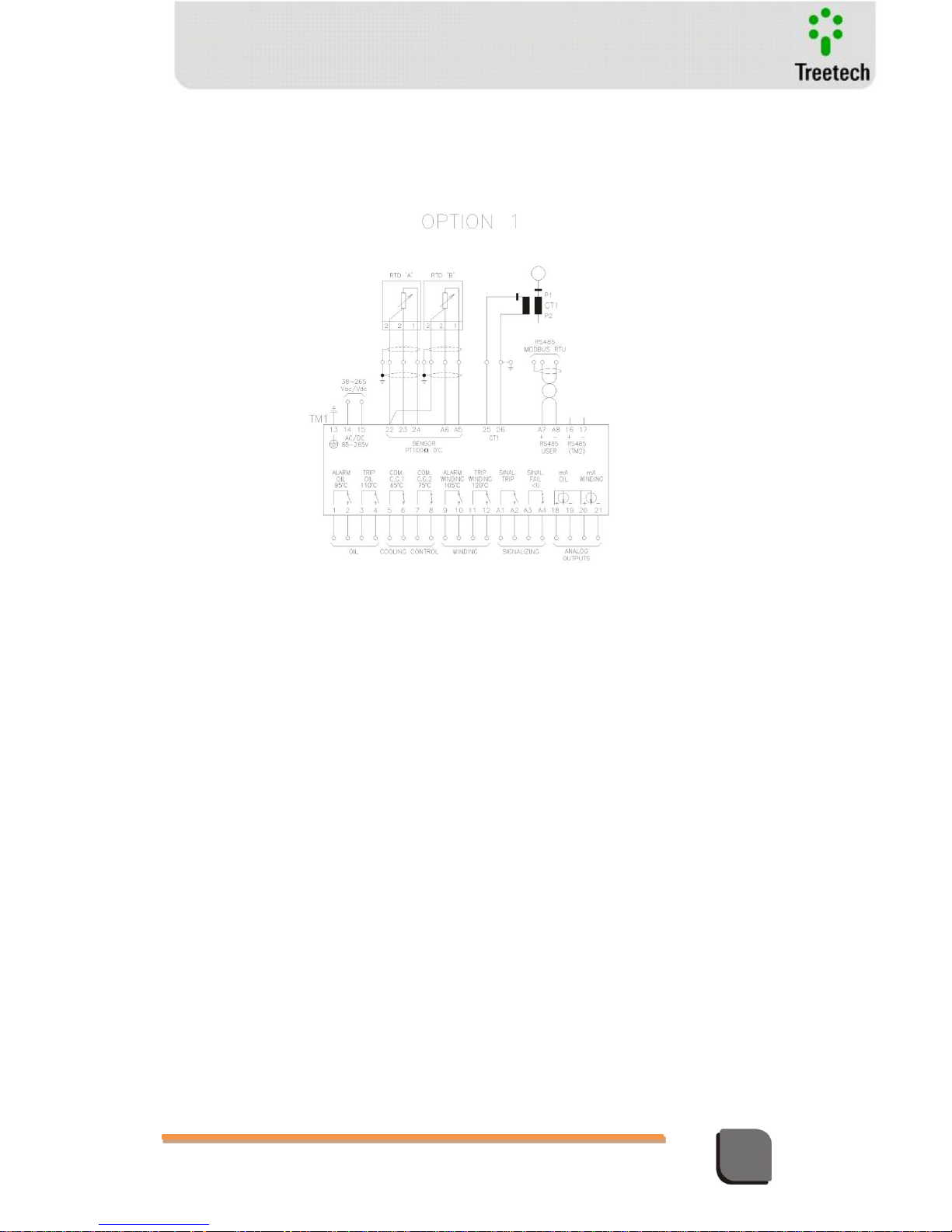
Technical Manual – TM1/TM2 | MA-010| 2016-03-21 | Ver.: 6.30 41
Temperature Monitor
4.4 Typical Application Diagrams
RTD Sensors – Option 1
Figure 18 – Option 1 – 2 RTDs with 3 wires
This connection option can be
used for:
a) Redundant measurement of
top oil temperature – in this
case both temperature
sensors A and B must be
located in the same top oil
region; or
b) Top oil temperature
measurement with sensor A
and a second temperature,
for instance ambient or
load tap changer with
sensor B.
Page 42
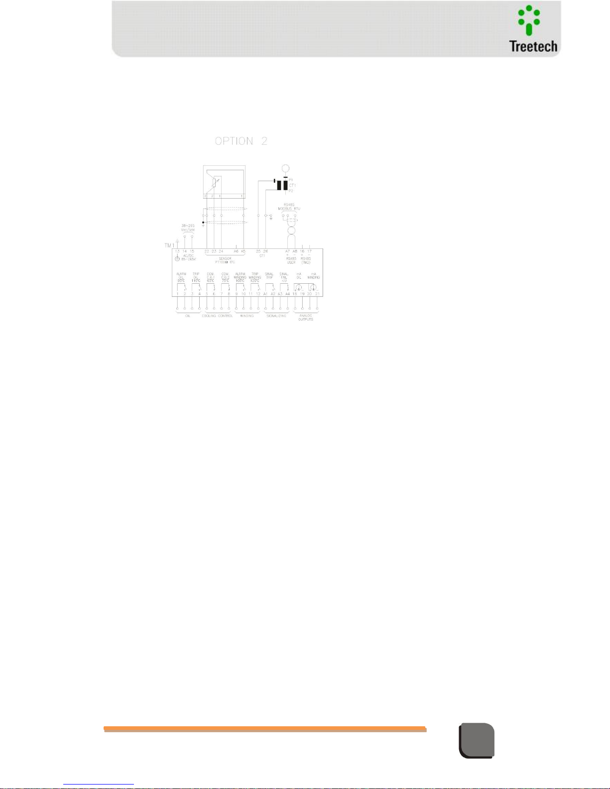
Technical Manual – TM1/TM2 | MA-010| 2016-03-21 | Ver.: 6.30 42
Temperature Monitor
RTD Sensors - OPTION 2
Figure 19 - Option 2 – 1 RTD with 4 wires
At this connection option,
the sensor must be used
for top oil temperature
measurement.
Page 43
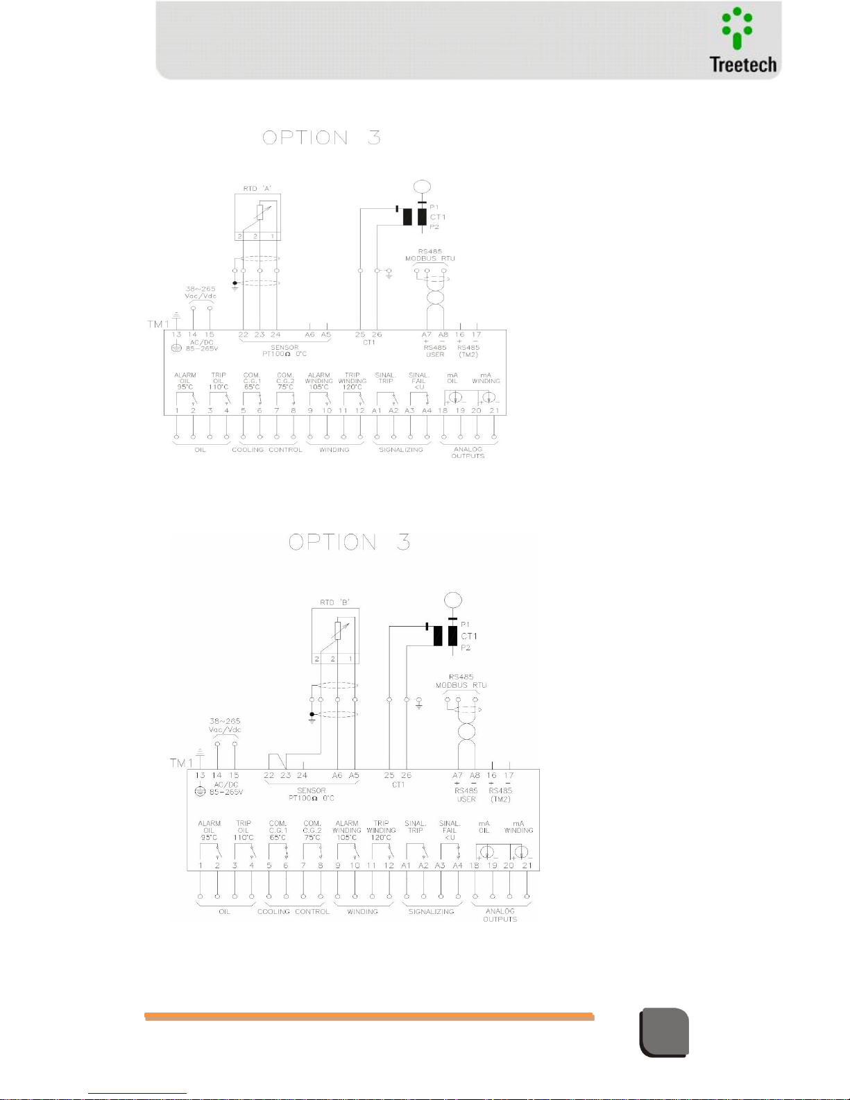
Technical Manual – TM1/TM2 | MA-010| 2016-03-21 | Ver.: 6.30 43
Temperature Monitor
RTD Sensors - OPTION 3
Figure 20 – Option 3 – 1 RTD with 3 wires, RTD A
RTD Sensors - OPTION 4
Figure 21 – Option 4 – 1 RTD with 3 wires, RTD B
At this connection option
the temperature sensor B
must be used for top oil
temperature
measurement.
At this connection option the
temperature sensor B must
be used for top oil
temperature measurement.
Page 44
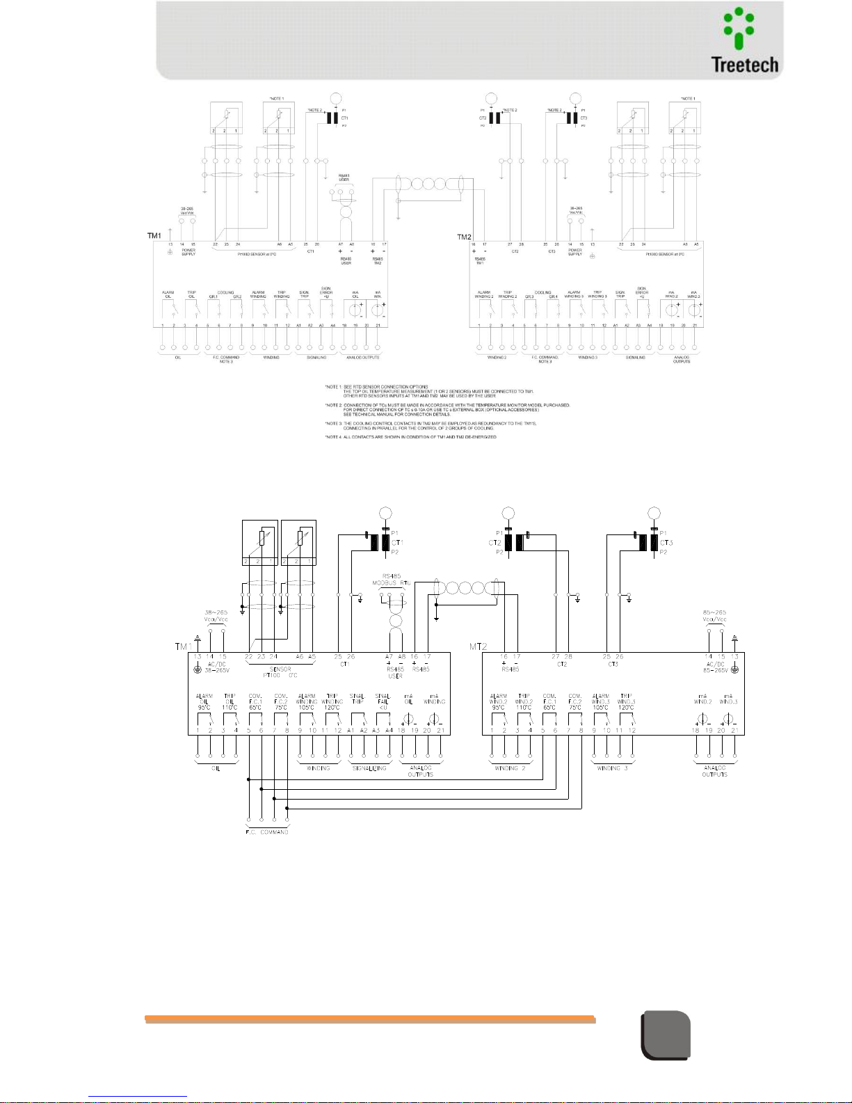
Technical Manual – TM1/TM2 | MA-010| 2016-03-21 | Ver.: 6.30 44
Temperature Monitor
Figure 22 – Connection TM1/TM2
Figure 23 – Connection TM1 / MT2
Page 45
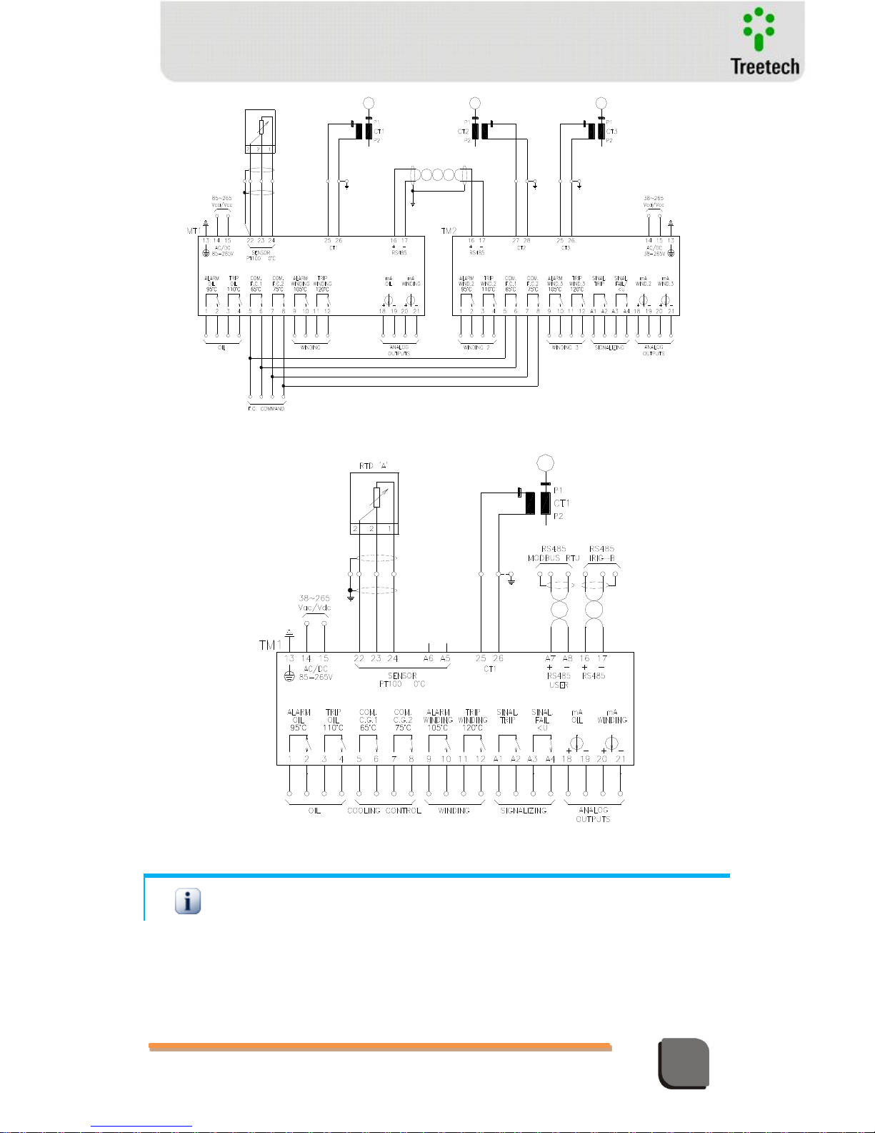
Technical Manual – TM1/TM2 | MA-010| 2016-03-21 | Ver.: 6.30 45
Temperature Monitor
Figure 24 – Connection MT1 / TM2
Figure 25 – Connection TM1 / synchronism signal IRIG-B
Whenever only use the input B’s PT-100 of TM1 / TM2, check the mandatory connection between
points 22 and 23.
Page 46
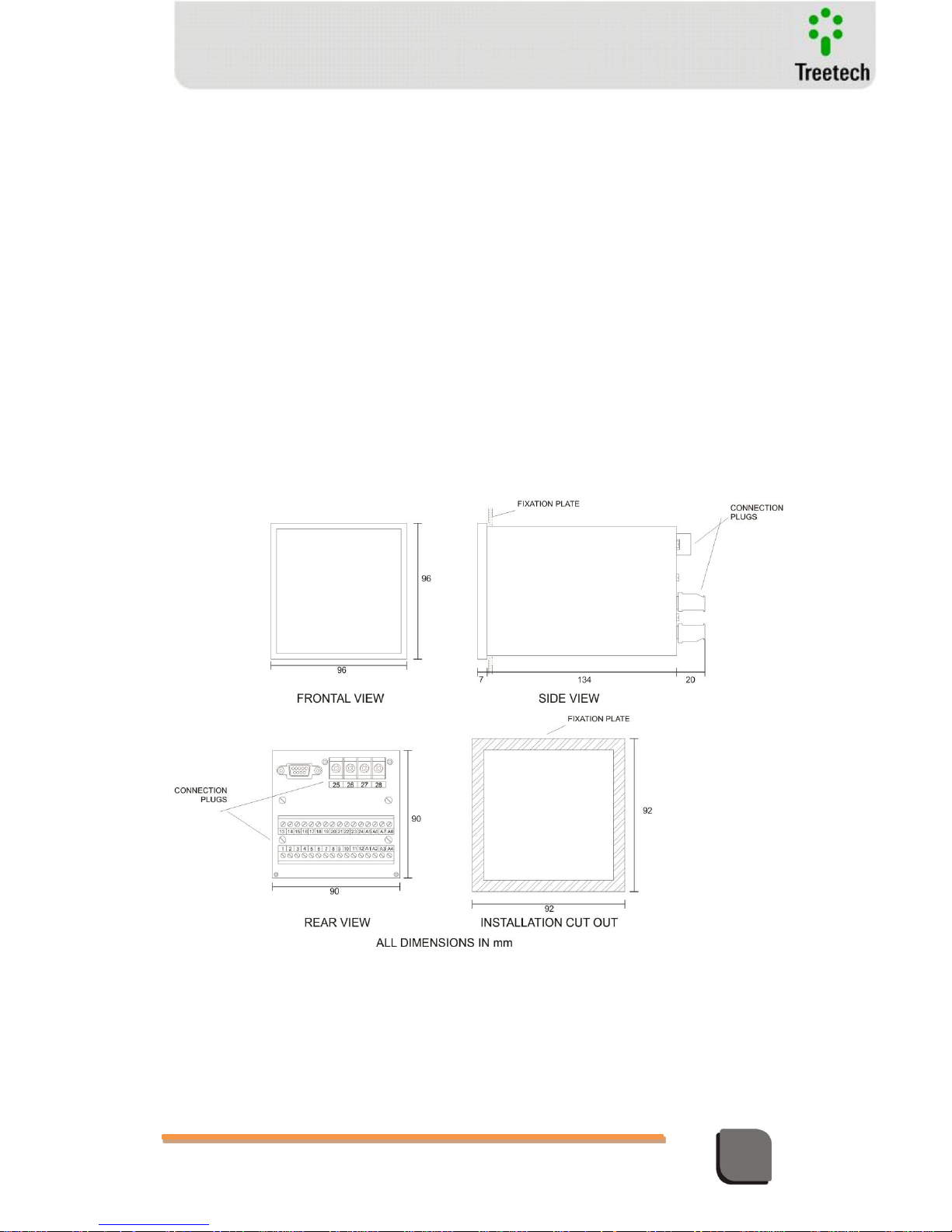
Technical Manual – TM1/TM2 | MA-010| 2016-03-21 | Ver.: 6.30 46
Temperature Monitor
4.5 Mechanical Installation
The Temperature Monitors must be installed protected from inclement weather conditions,
meaning inside panel boxes or housed in buildings. In any case, there must always be anticondensation systems.
The Temperature Monitors TM1 and TM2 are suitable for built in type installations, and can,
for instance, be fixed on doors or front plates of panels. Fixation clips are supplied with the
devices. The figure below shows the main dimensions of the equipment, as well as the
dimensions of the cut out that must be made on the plate to fit it in. Special attention must be
given to the thickness of the layers of the paint coat on the plate where the cutout is made,
since in some cases, when very thick paint is used, the resulting reduction on the area of the
cutout might even make it impossible to install the equipment. Connection terminals are
installed in the rear of the TM1 and TM2, 2 removable connectors and in threaded terminals
(CT connection for thermal imaging), in order to facilitate the connections. 0.5 to 2.5mm²
cables can be used, bare or with “pin” type terminals (or “needle”) for removaqble connectors,
and up to 6mm for the CT connectors with adequate ring-type terminals.
Figure 26 – Dimensions of TM1 and TM2
Page 47

Technical Manual – TM1/TM2 | MA-010| 2016-03-21 | Ver.: 6.30 47
Temperature Monitor
5 Parameterization
In order to ensure the correct operation of the system, several parameters that will supply the
equipment with the information needed for its operation must be adjusted on the TM1 and
TM2. These adjustments can be made by way of the front panel keyboard using the display, or
through the parameter definition software, by way of the serial communication ports RS232 or
RS485, available for the user on the rear panel of the equipment.
The programmable parameters are organized into password protected menus. From the main
menu, users will have access to the programming submenus, where they are able to navigate
and adjust values in accordance with the transformer’s characteristics and user needs.
5.1 Programming
Parameter programming on the Temperature Monitors TM1 and TM2 must be performed
during the installation or system commissioning procedures. Adjustments are saved to a nonvolatile memory.
When the desired submenu is displayed, press the key to access it and carry out parameter
programming.
Page 48
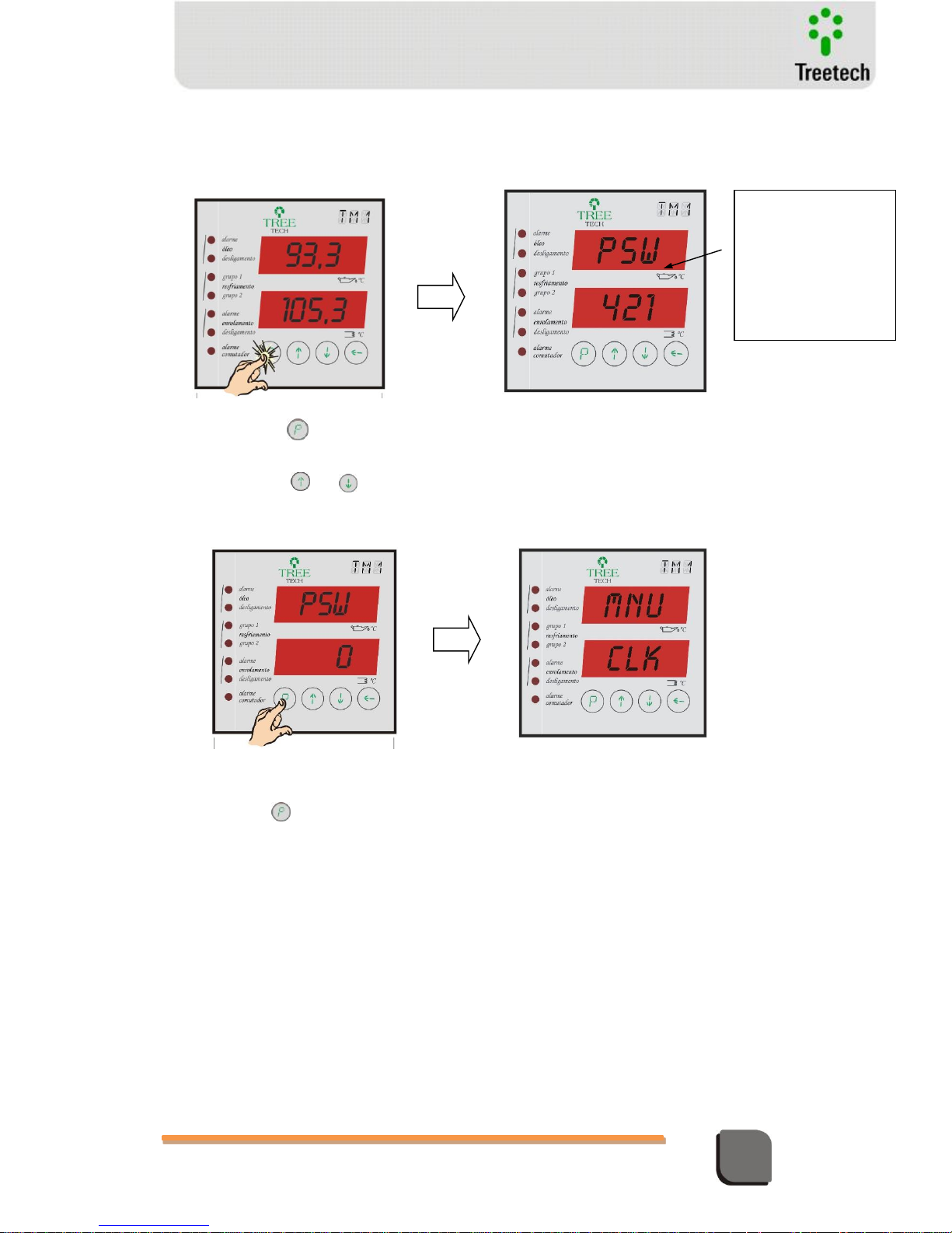
Technical Manual – TM1/TM2 | MA-010| 2016-03-21 | Ver.: 6.30 48
Temperature Monitor
3) ) Using the and keys adjust the password (range = 0 to 999). If initial
indication is 421 the password is the factory default, zero. Password can be changed
by users
5.2 Access to the Programming Menu
To access the programming menu of the Monitors TM1 and TM2, follow the procedure
described below:
1) On the temperature reading screen,
press and hold the key for 5 seconds
The initial number
that is shown when this
parameter is reached
serves to recover the
password. Inform this
number to our Technical
Assistance Dept. for
decoding.
2) The access password screen
will come up.
5) Main menu screen, from where it is
possible to navigate to the programming
submenus.
4) After adjusting the password, press
and release the key to enter the
programming menu.
Page 49
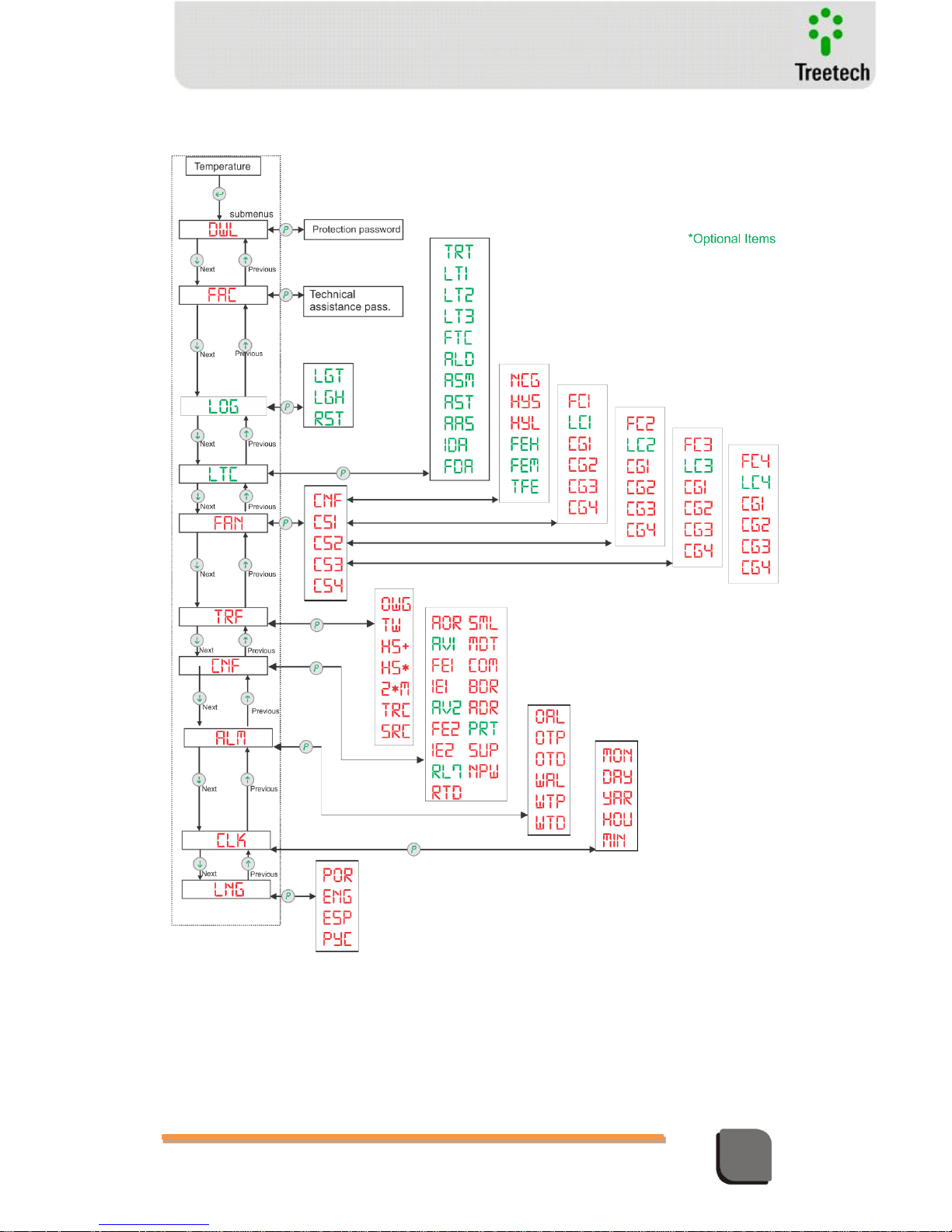
Technical Manual – TM1/TM2 | MA-010| 2016-03-21 | Ver.: 6.30 49
Temperature Monitor
5.3 Access to submenus
Page 50
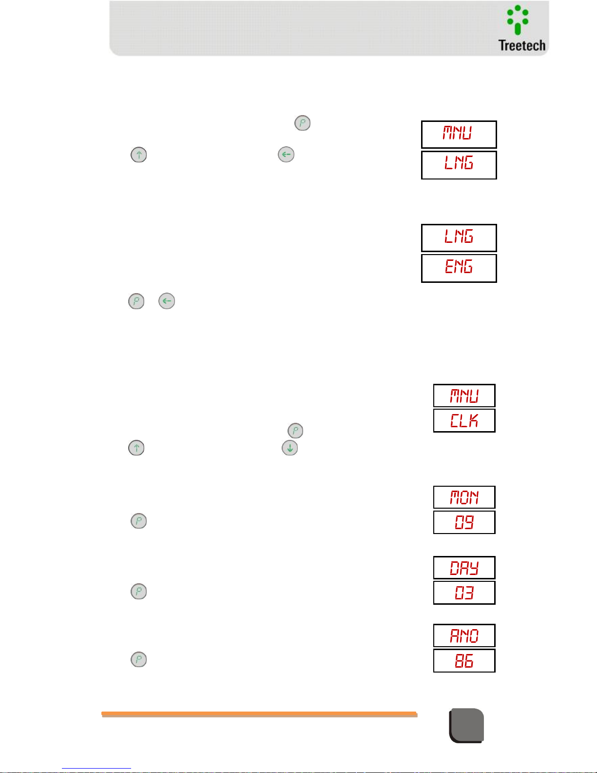
Technical Manual – TM1/TM2 | MA-010| 2016-03-21 | Ver.: 6.30 50
Temperature Monitor
Submenu LNG
Allows the selection of the device’s operation language.
With display showing
mnu / LNG
, press to access the
parameters or;
Press to access
mnu / RLG
, or to return to measurement
indication.
LNG – TM1/TM2 language selection
Set range:
POR = Portuguese;
ENG = English;
ESP = Spanish;
PYC = Russian.
Press or to return to main menu.
Submenu CLK
Permite ajustar o relógio e calendário do aparelho. Este ajuste é efetuado
somente no TM1.
Opcionalmente o ajuste do relógio pode ser efetuado pelo protocolo DNP3.0
ou pela entrada IRIG-B, se disponíveis, que realizam o sincronismo do relógio
via GPS.
When display shows
mnu / CLK
, press to access parameters, or;
Press to access
mnu / ALM
, or to return to measurement
indication.
MON –Month
Set Range: 1 to 12 months, in steps of 1 month.
Press to acces parameter DAY
DAY – Day
Set Range: 1 to 31 dias, in steps of 1 day.
Press to access parameter YAR
YAR – Year
Set Range: 3 to 99 (year 2003 to 2099), in steps of 1 year.
Press to access parameter HOR
Page 51
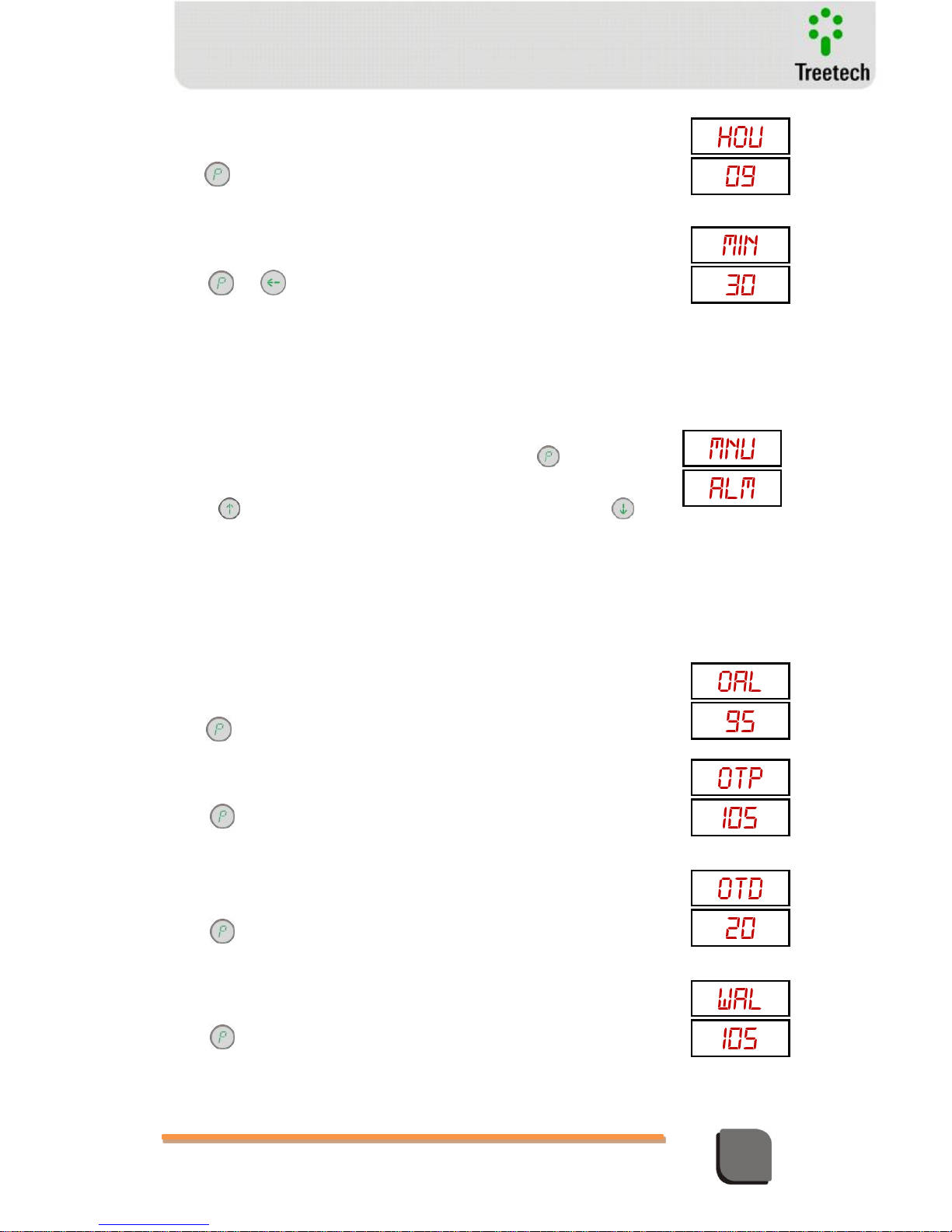
Technical Manual – TM1/TM2 | MA-010| 2016-03-21 | Ver.: 6.30 51
Temperature Monitor
HOU – Hour
Set Range: 0 to 23 hours, in 1 hour steps.
Press to access parameter MIN.
MIN – Minute
Set Range: 0 to 59 minutes, in 1 minute steps.
Press or to return to main menu
Submenu ALM
This submenu permits access to all parameters relative to alarms and
trips. Extended temperature range from -55 to 200°C for 4-key hardware
and from 0 to 150°C for 3-key hardware.
With the display showing
mnu / ALM
, press the key for access
to alarm parameters or;
Press key to go to the configuration menu mnu / cfn , or the key
to return to the menu
mnu / CLK
.
5.3.1.1 TM1 Temperature Monitor – Submenu ALM
OAL – oil temperature alarm
Adjustment range: -55 to 200ºC, in 1ºC increments
Press key to advance to parameter OTP
OTP – trip due to oil temperature
Adjustment range : -55 to 200ºC, in 1ºC increments
Press key to advance to parameter OTD
OTD – trip due to oil temperature delay
Adjustment range: 0 to 20 min., in 0.1min. increments
Press key to advance to parameter WAL
WAL – winding 1 temperature alarm
Adjustment range: -55 to 200ºC, in 1ºC increments
Press key to advance to parameter WTP
Page 52
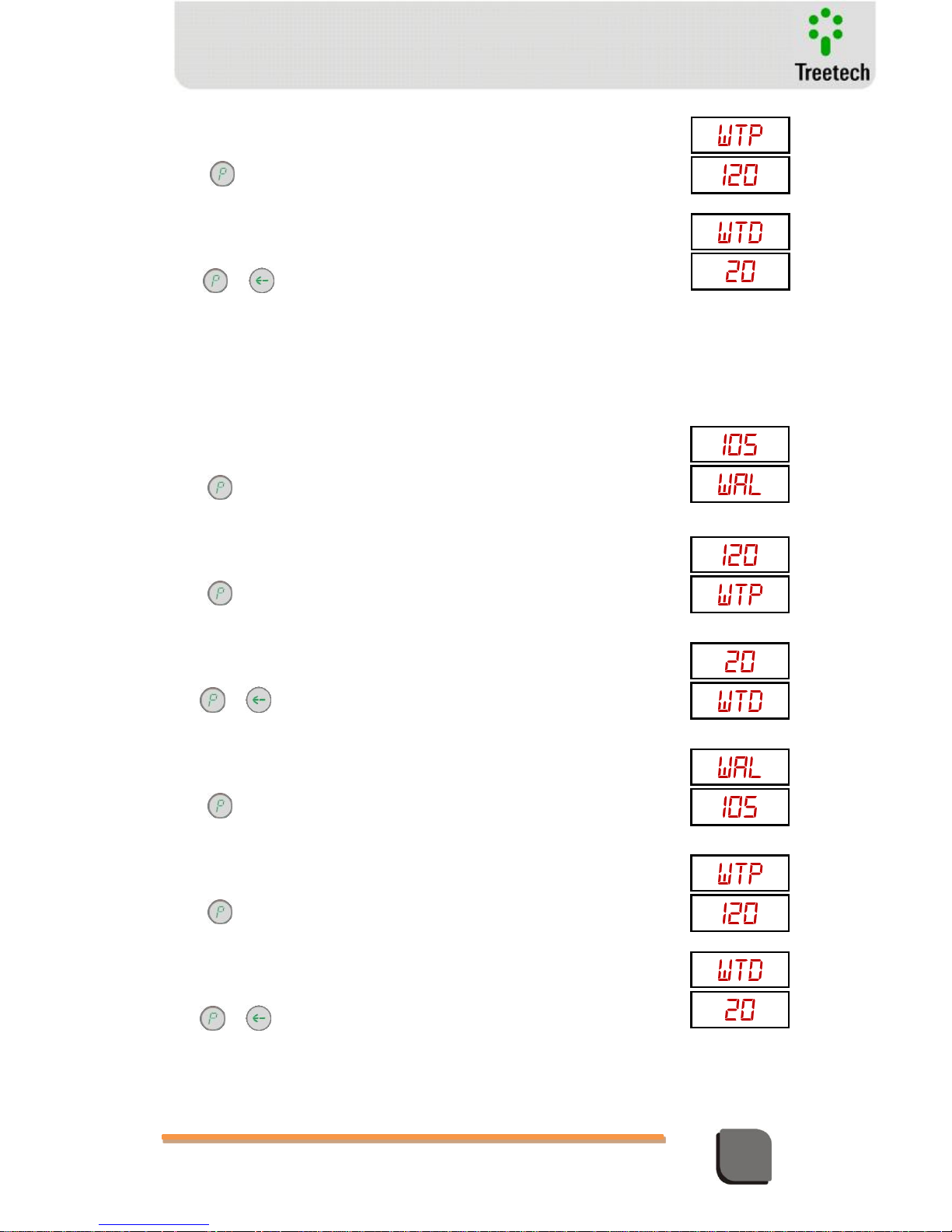
Technical Manual – TM1/TM2 | MA-010| 2016-03-21 | Ver.: 6.30 52
Temperature Monitor
WTP – trip due to temperature in winding 1
Adjustment range: -55 to 200ºC, in 1ºC increments
Press key to advance to parameter WTD
WTD – delay for trip due to temperature in winding 1
Adjustment range: 0 to 20 min., in 0.1min. increments
Press or key to return to the main menu
5.3.1.2 TM2 Temperature Monitor – Submenu ALM
WAL – winding 2 temperature alarm
Adjustment range: -55 to 200ºC, in 1ºC increments
Press key to advance to parameter WTP
WTP – trip due to temperature in winding 2
Adjustment range: -55 to 200ºC, in 1ºC increments
Press key to advance to parameter WTD
WTD – delay for trip due to temperature in winding 2
Adjustment range: 0 to 20 min., in 0.1min. increments
Press or key to return to the main menu
WAL – winding 3 temperature alarm
Adjustment range: -55 to 200ºC, in 1ºC increments
Press key to advance to parameter WTP
WTP – trip due to temperature in winding 3
Adjustment range: -55 to 200ºC, in 1ºC increments
Press key to advance to parameter WTD
WTD – delay for trip due to temperature in winding 3
Adjustment range: 0 to 20 min., in 0.1min. increments
Press or key to return to the main menu
Page 53
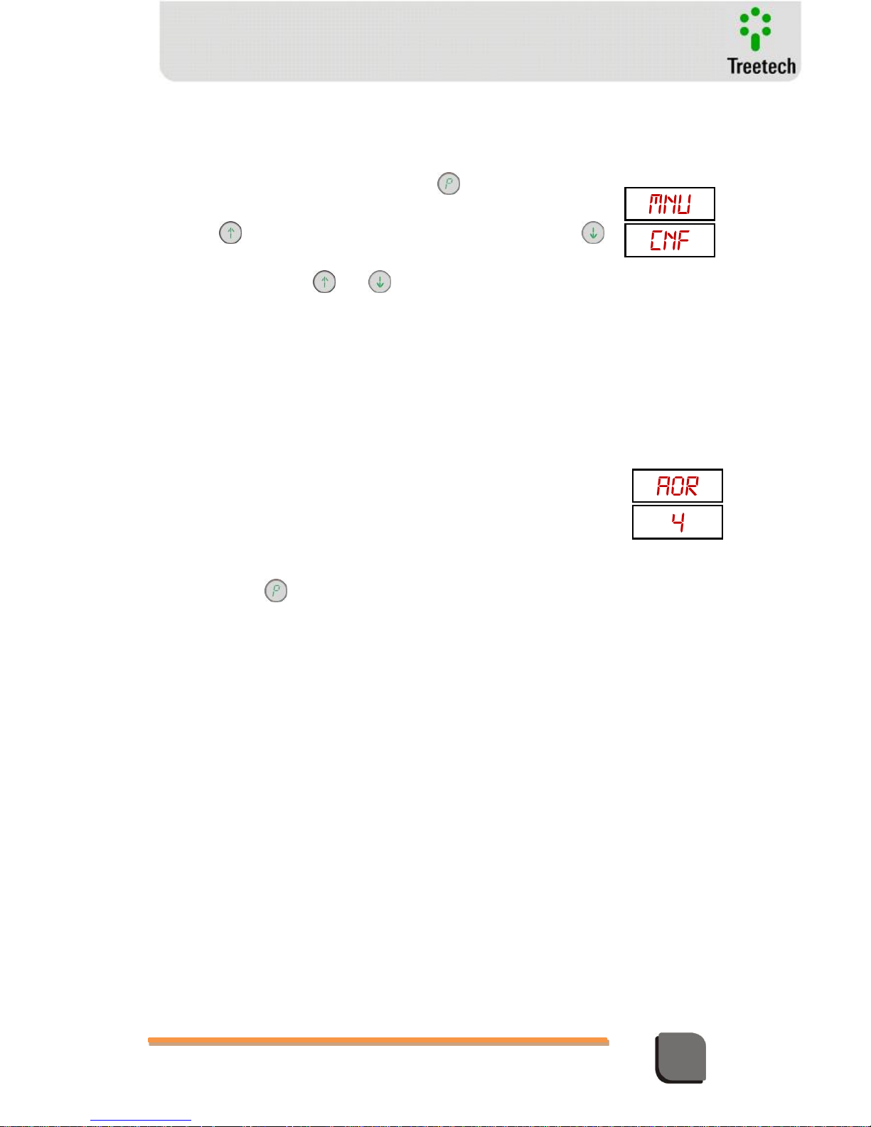
Technical Manual – TM1/TM2 | MA-010| 2016-03-21 | Ver.: 6.30 53
Temperature Monitor
Submenu CNF
Allows the device’s operation parameters to be accessed
With the display showing mnu / CNF, press the for access to
configuration parameters or;
Press the key to go to the configuration menu mnu / TRF , or
to return to the menu mnu / ALM.
In each parameter use the and keys to set the desired value.
5.3.1.3 Monitor de Temperatura TM1 – Submenu CNF
AOR – analog output range (mA). Selects the current loop range for remote
reading.
Seleciona o padrão do loop de corrente para indicação remota.
Adjustment range: 0 = 0...1 mA
1 = 0...5 mA
2 = 0...10mA
3 = 0...20mA
4 = 4...20mA
Pressionar a tecla para avançar ao parâmetro Va1
Page 54
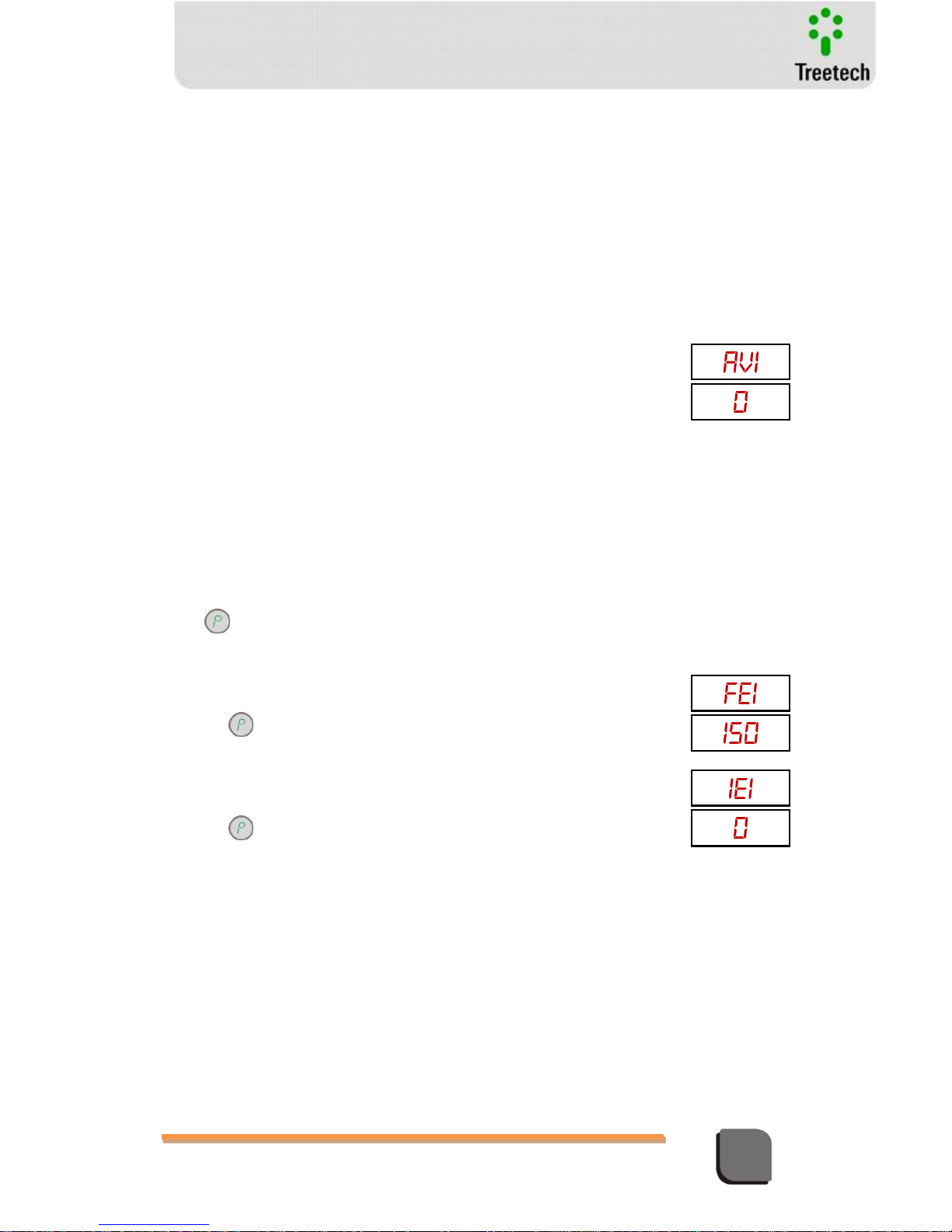
Technical Manual – TM1/TM2 | MA-010| 2016-03-21 | Ver.: 6.30 54
Temperature Monitor
AV1 – analog variable associated to the analog output 1
Selection of the variable associated to the analog output 1. This parameter
will only be shown if the optional for LTC temperature differential is
available.
Adjustment range:
0 – Oil temperature
1 – Winding 1 temperature
2 – Winding 2 temperature
3 – Winding 3 temperature
4 – Hottest winding temperature
5 – Temperature sensor A (PTA) connected to TM1
6 – Temperature sensor B (PTB) connected to TM1
7 – Temperature sensor A (PTA) connected to TM2
8 – Temperature sensor B (PTB) connected to TM2
9 – Instantaneous temperature differential of LTC 1
10 – Instantaneous temperature differential of LTC 2
11 – Instantaneous temperature differential of LTC 3
12 – Highest instantaneous temperature differential among the 3 LTCs
13 – Filtered temperature differential of LTC 1
14 – Filtered temperature differential of LTC 2
15 – Filtered temperature differential of LTC 3
16 – Highest filtered temperature differential among the 3 LTCs
Press to access parameter FE1
FE1 – Value for the variable for current output 1 end of scale
Adjustment range: -55 to 200ºC in increments of 1ºC.
Press key to move to parameter IE1
IE1 – Value for the variable for current output 1 beginning of scale
Adjustment range: -55 to 200ºC in increments of 1ºC.
Press key to move to parameter AV2.
Page 55
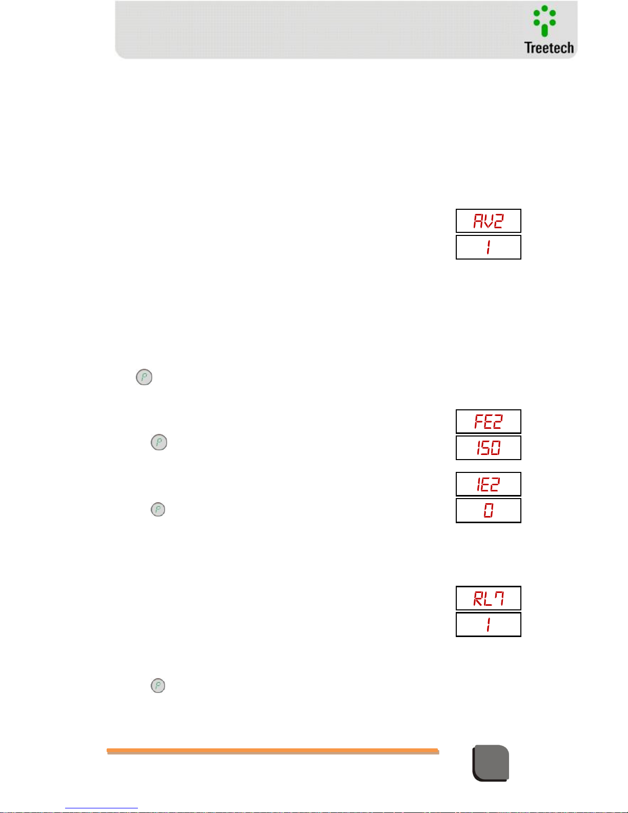
Technical Manual – TM1/TM2 | MA-010| 2016-03-21 | Ver.: 6.30 55
Temperature Monitor
VA2 – Variável Associada à Saída de Corrente 2
Selection of the variable associated to the analog output 2. This parameter
will only be shown if the optional for LTC temperature differential is
available. Adjustment range:
Faixa de ajuste:
0 – Oil temperature
1 – Winding 1 temperature
2 – Winding 2 temperature
3 – Winding 3 temperature
4 – Hottest winding temperature
5 – Temperature sensor A (PTA) connected to TM1
6 – Temperature sensor B (PTB) connected to TM1
7 – Temperature sensor A (PTA) connected to TM2
8 – Temperature sensor B (PTB) connected to TM2
9 – Instantaneous temperature differential of LTC 1
10 – Instantaneous temperature differential of LTC 2
11 – Instantaneous temperature differential of LTC 3
12 – Highest instantaneous temperature differential among the 3 LTCs
13 – Filtered temperature differential of LTC 1
14 – Filtered temperature differential of LTC 2
15 – Filtered temperature differential of LTC 3
16 – Highest filtered temperature differential among the 3 LTCs
Press key to advance to parameter FE2
FE2 - sets the value for the variable for current output 2 end of scale
Adjustment range: -55 to 200ºC in increments of 1ºC.
Press key to move to parameter IE2
IE2 - sets the value for the variable for current output 2 beginning of scale
Adjustment range: -55 to 200ºC in increments of 1ºC.
Press key to move to parameter rL7.
RL7 – Signaling function of output relay 7
Selection of the signaling function associated to the output relay 7. This
parameter will only be shown if the optional for LTC temperature differential
is available; otherwise the relay will assume the default function of
instantaneous signaling of trip. Adjustment range:
0 – Instantaneous signaling of trip – one or more trip contacts actuated or in
countdown process for trip.
1 – Alarm by instantaneous LTC temperature differential
2 – Alarm by filtered LTC temperature differential
3 – Alarm by instantaneous or filtered LTC temperature differential.
Press key to move to parameter RTD.
Page 56
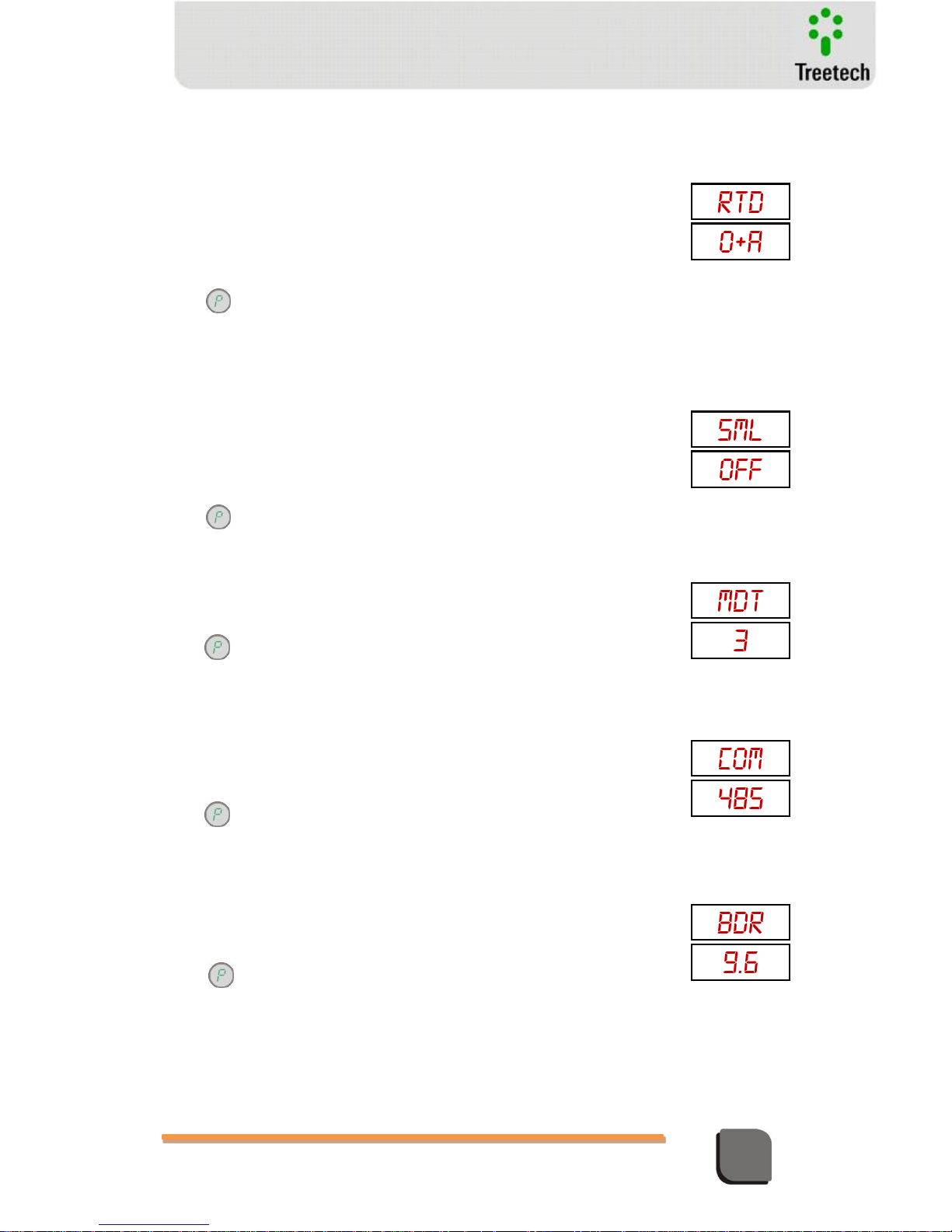
Technical Manual – TM1/TM2 | MA-010| 2016-03-21 | Ver.: 6.30 56
Temperature Monitor
RTD – Selects the connection option of the temperature sensor
Adjustment range:
2X3 = 2 redundant Pt100 3-wire sensors for oil temperature
1X4 = 1 Pt100 4-wire sensor for oil temperature
X3A = 1 Pt100 3-wire sensor in input A for oil temperature
X3B = 1 Pt100 3-wire sensor in input B for oil temperature
O+A = 2 sensors Pt100 3-wires to measure oil temperature (sensor A) and
another temperature, for instance ambient, LTC or other (sensor B)
Press key to advance to parameter SML
SML – Pt100 input check by way of electronic RTD simulator
Adjustment Range:
During normal system operation, this parameter must be selected to “OFF”.
Every time the device is switched off and on again, this parameter defaults to
“OFF”
Press key to advance to parameter MDT
MDT – Maximum permissible difference between 2 Pt100 with 3 wires, when the
option 2x3 is used at parameter RTD
Adjustment range: 1 to 6 ºC, in steps of 0,1 ºC
Press to access parameter COM.
COM – Selection of Communication Port
Adjustment range: 232 = use serial RS232 (connector DB9)
485 = use serial RS485 (terminals A7 e A8).
The standard protocol used is MODBUS-RTU; optionally, the 1ms DNP-3.0
with time-stamp protocol can be supplied.
Press to access parameter BDR.
BDR – Baud Rate
Adjustment range: 9.6 = 9,6 kbps
19.2 = 19,2 kbps
38.4 = 38,4 kbps
Press to access the parameter END
ON = use electronic simulator of external Pt100 in simulation.
OFF = use real Pt100 sensor for temperature reading.
Page 57
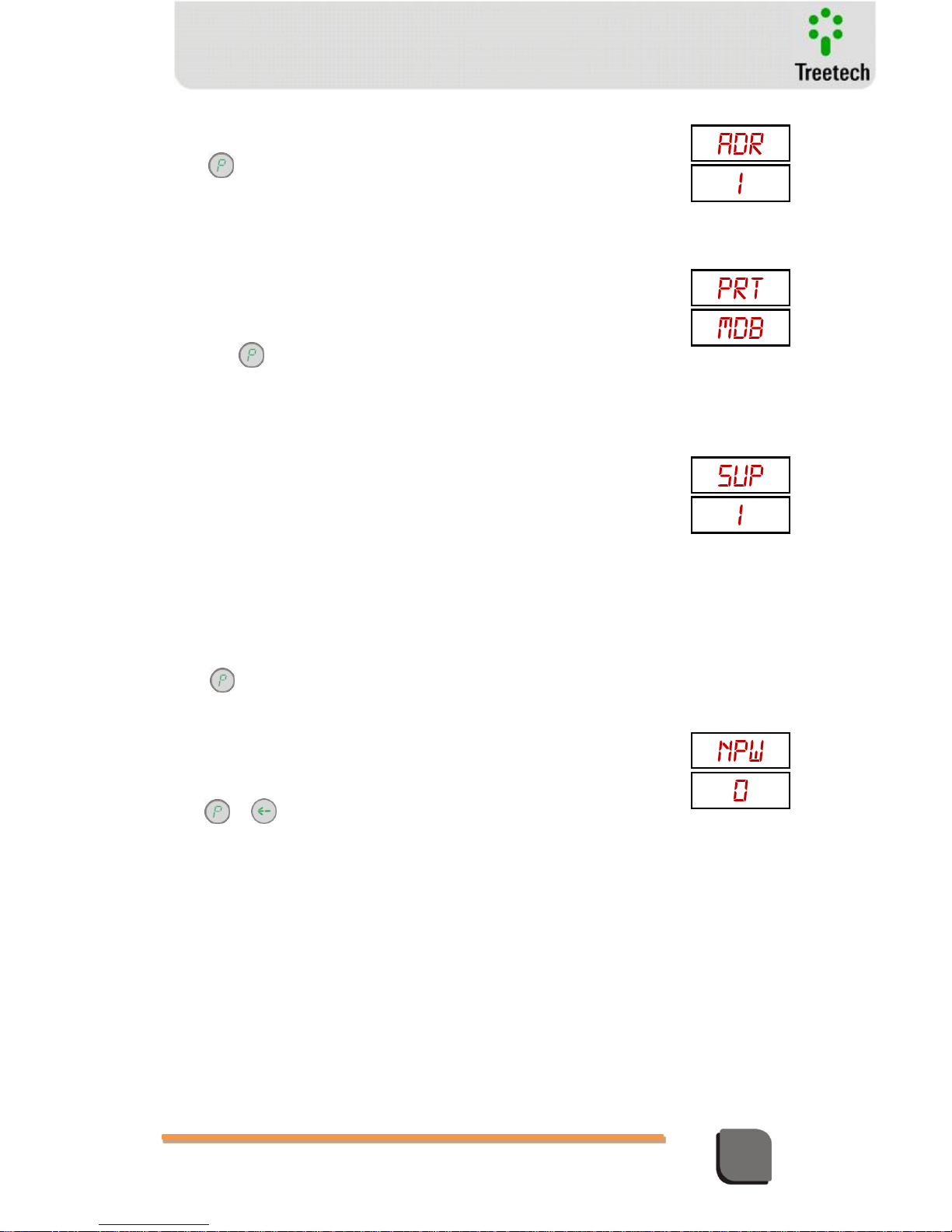
Technical Manual – TM1/TM2 | MA-010| 2016-03-21 | Ver.: 6.30 57
Temperature Monitor
ADR – device address for communication with TM1
Adjustment Range: 1 to 31, in steps of 1.
Press to access parameter PRT (if the optional DNP3.0 is available) or
SUP.
PRT – Communication Protocol (optional)
This parameter will be shown only if the optional function DNP 3.0 is
available.
Adjustment range: MDB = MODBUS-RTU
DNP = DNP 3.0 with 1ms time-stamp de
Pressionar to access parameter SUP
SUP – Supervision Mode
Informs which devices are connected on the
temperature monitoring system
Adjustment
range:
0 = only TM1
1 = TM1 + TM2
2 = Not used (reserved option)
3 = Not used (reserved option)
4 = TM1 + MT2
5 = TM1 + IRIG-B
Remarks.:
1) Using TM1 + MT2 (SUP = 4), the MT2 address must be 1.
2) Using the option TM1 + IRIG-B the use of TM2 module is not possible
Press key to advance to parameter LNG
NPW – Sets new password for access to programming menus
Adjustment range: 0 to 999 in steps of 1.
Default password = 0.
Press o to return to main menu.
Page 58
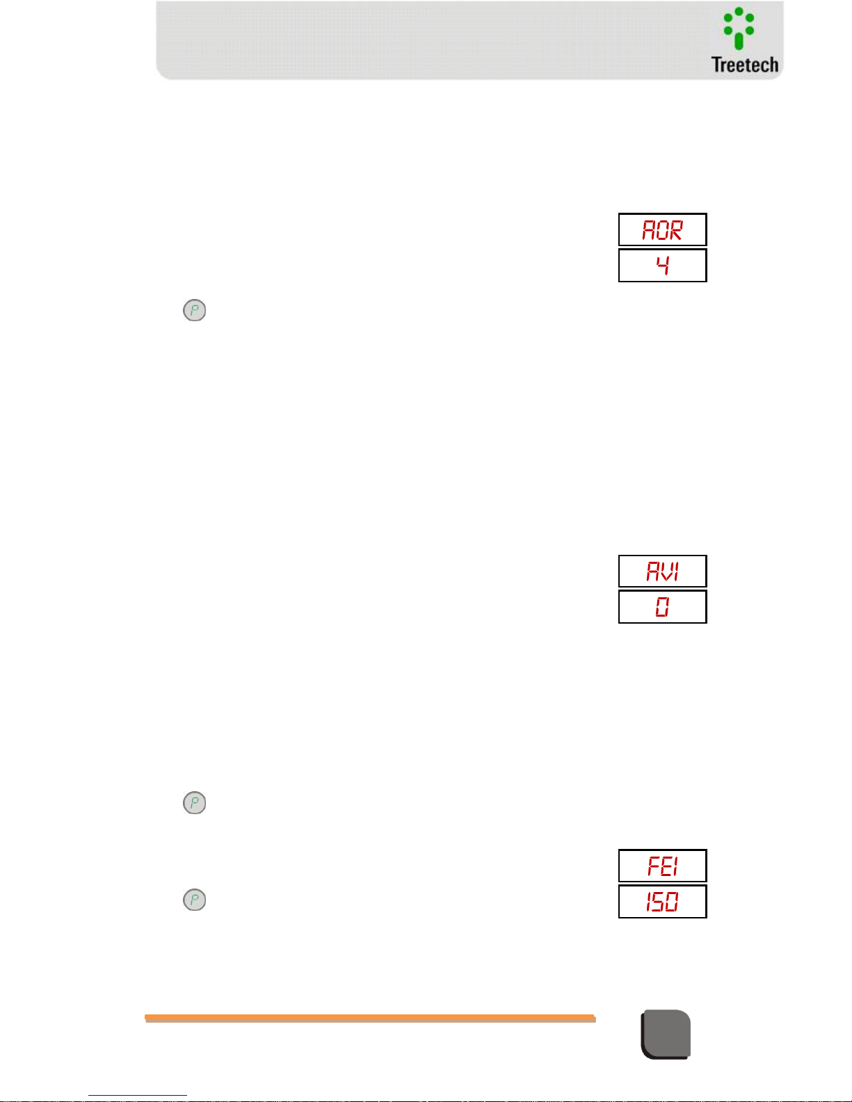
Technical Manual – TM1/TM2 | MA-010| 2016-03-21 | Ver.: 6.30 58
Temperature Monitor
5.3.1.4 Temperature Monitor TM2 – Submenu CNF
AOR – Analog output range (mA)
Selects current loop range for remote reading.
Adjustment range: 0 = 0...1 mA
1 = 0...5 mA
2 = 0...10mA
3 = 0...20mA
4 = 4...20mA
Press to access parameter AV1
AV1 – Variable associated do the analog output 1
Selection of the variable associated to the analog output 1. This parameter
will only be shown if the optional for LTC temperature differential is
available.
Adjustment range.
0 – Oil temperature
1 – Winding 1 temperature
2 – Winding 2 temperature
3 – Winding 3 temperature
4 – Hottest winding temperature
5 – Temperature sensor A (PTA) connected to TM1
6 – Temperature sensor B (PTB) connected to TM1
7 – Temperature sensor A (PTA) connected to TM2
8 – Temperature sensor B (PTB) connected to TM2
9 – Instantaneous temperature differential of LTC 1
10 – Instantaneous temperature differential of LTC 2
11 – Instantaneous temperature differential of LTC 3
12 – Highest instantaneous temperature differential among the 3 LTCs
13 – Filtered temperature differential of LTC 1
14 – Filtered temperature differential of LTC 2
15 – Filtered temperature differential of LTC 3
16 – Highest filtered temperature differential among the 3 LTCs
Press to access parameter FE1
FE1 – VAlue for the variable for current output 1 end of scale
Adjustment range: -55 to 200ºC in steps of 1ºC.
Press to access parameter IE1
Page 59
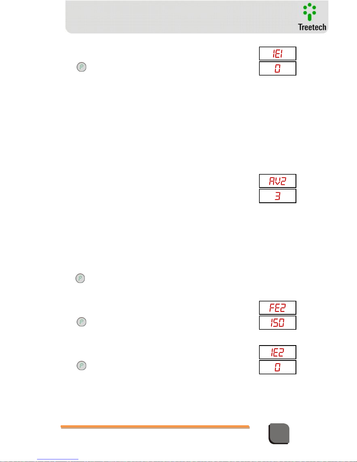
Technical Manual – TM1/TM2 | MA-010| 2016-03-21 | Ver.: 6.30 59
Temperature Monitor
IE1 – Value for the variable for current output 1 end of scale
Adjustment range: -55 to 200ºC in steps of 1 ºC.
Press to access parameter AV2.
AV2 – Variable associated to the analog output 2
Selection of the variable associated to the analog output 2. This parameter
will only be shown if the optional for LTC temperature differential is
available.
Adjustment Range:
0 0 – Oil temperature
1 – Winding 1 temperature
2 – Winding 2 temperature
3 – Winding 3 temperature
4 – Hottest winding temperature
5 – Temperature sensor A (PTA) connected to TM1
6 – Temperature sensor B (PTB) connected to TM1
7 – Temperature sensor A (PTA) connected to TM2
8 – Temperature sensor B (PTB) connected to TM2
9 – Instantaneous temperature differential of LTC 1
10 – Instantaneous temperature differential of LTC 2
11 – Instantaneous temperature differential of LTC 3
12 – Highest instantaneous temperature differential among the 3 LTCs
13 – Filtered temperature differential of LTC 1
14 – Filtered temperature differential of LTC 2
15 – Filtered temperature differential of LTC 3
16 – Highest filtered temperature differential among the 3 LTCs
Press to access parameter FE2
FE2 – Value for the variable for current output 2 beggining of scale
Adjustment range: -55 to 200ºC in steps of 1ºC.
Press to access parameter IE2
IE2 – Value for the variable for current output 2 end of scale
Adjustment range: -55 to 200ºC in steps of 1 ºC.
Press to access parameter IE2
Page 60
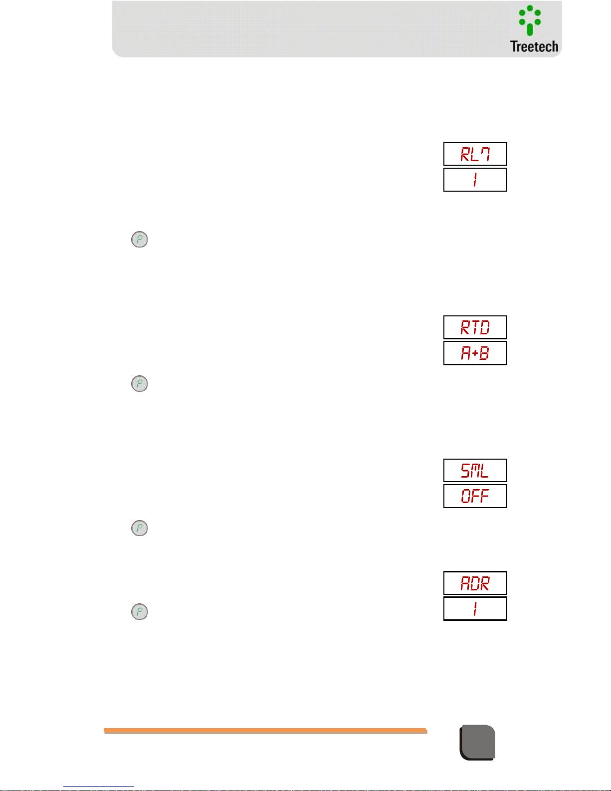
Technical Manual – TM1/TM2 | MA-010| 2016-03-21 | Ver.: 6.30 60
Temperature Monitor
RL7 – Signaling function of output relay 7 (optional)
Selection of the signaling function associated to the output relay 7. This
parameter will only be shown if the optional for LTC temperature differential
is available; otherwise the relay will assume the default function of
instantaneous signaling of trip.
Adjustment range:
0 - Instantaneous signaling of trip – one or more trip contacts actuated or in
countdown process for trip.
1 – Alarm by instantaneous LTC temperature differential
2 – Alarm by filtered LTC temperature differential
3 – Alarm by instantaneous or filtered LTC temperature differential.
Press to access parameter RTD
RTD – Selects the connection option of the temperature sensor
Adjustment range:
OFF = no temperature sensor connected
1X4 = 1 Pt100 4-wire sensor
X3A = 1 Pt100 3-wire sensor in input A
X3B = 1 Pt100 3-wire sensor in input B
A+B = 2 sensors Pt100 3-wires
Press to access parameter SML
SML – Pt100 input check by way of elecctronic RTD simulator
Adjustment range:
During normal system operation, this parameter must be selected to “OFF”.
Every time the device is switched off and the on again, this parameter
defaults to “OFF”.
Press to advance to parameter ADR
ADR – Device address for communication with TM1
When configuration TM1+TM2 is used, this parameter must be 1.
Adjustment range: 1 to 31
Press to access parameter DSP
ON = use electronic simulator of external Pt100 in simulation.
OFF use real Pt100 sensor for temperature reading.
Page 61
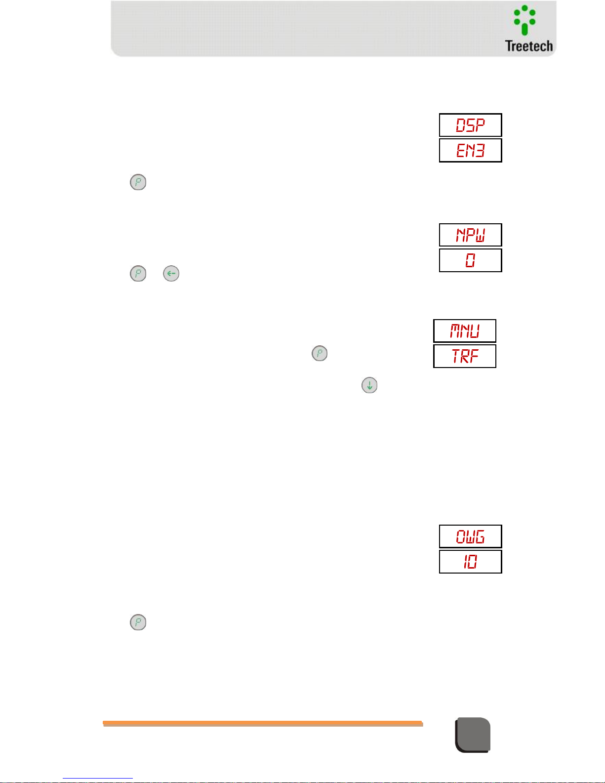
Technical Manual – TM1/TM2 | MA-010| 2016-03-21 | Ver.: 6.30 61
Temperature Monitor
DSP – Indicates variable to be shown at display correspondente to Winding 3,
present in TM2.
Adjustment range:
PTA = Temperature sensor A connected to TM2
PTB = Temperature sensor B connected to TM2
WG3 = Winding 3 temperature
OBS: The top display always show the Winding 2 measuring.
Press to access parameter NPW
NPW – Sets new password for access to programming menus
Adjustment range: 0 to 999 in steps of 1.
Default value = 0.
Press or to return to main menu.
Submenu TRF
Allows access to parameters relative to characteristics of the Transformer /
reactor.
With the display showing
mnu / TRF
, press to acces transformer
parameters;
Press to go to the configuration menu
mnu / FAN
, or to return
to the
mnu/ CNF
menu.
5.3.1.5 Temperature Monitor TM1 – Submenu TRF
OWG – Oil/Winding 1 temperature gradient
This value must be informed by the manufacturer of the transformer /
reactor. The figure is obtained by heat run tests or by calculation.
The OWG is defined by IEC 60076-7 as the difference between the average
temperature of the einding and the average temperature of the top oil, after
thermal stability is achieved under rated load conditions.
At NBR 5416 / IEEE C57.91-1995 the OWG is defined as the elevation of the
average temperature of the winding related to the average top oil
temperature, after termal stability is achieved under rated load conditions.
Adjustment range: 0 to 50ºC, in steps of 0,1ºC.
Press to access parameter TW.
Page 62
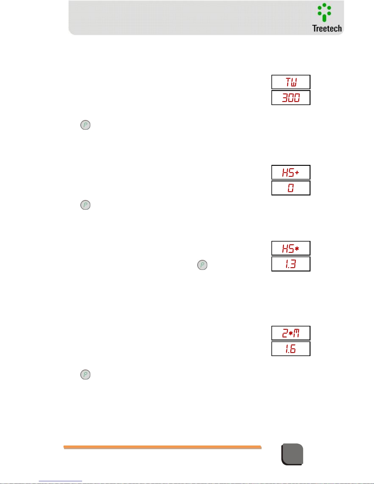
Technical Manual – TM1/TM2 | MA-010| 2016-03-21 | Ver.: 6.30 62
Temperature Monitor
TW – Time constant for the winding 1. This is the the time constant in seconds,
relative.
This is the time constant in seconds, relative to the thermal inertia of the
transformer’s winding 1.
This parameter can be measured during the transformer heat run test or
calculated by the manufacturer of the transformer. In case it cannot be
obtained either way, the typical value of 300 s can be adopted.
Adjustment Range: 72 to 999, in steps 1.
Press to access parameter HS+.
HS+ - Hot-spot factor (ANSI / ABNT)
This is the difference between the hottest-spot and the average temperature
of the winding, adopted by standards ABNT NBR 5416 e IEEE C57.91-1995.
If these standards are not being followed, this parameter must be set to 0
(zero).
Adjustment range: 0 to 20ºC, in steps of 0,1ºC.
Press to access parameter HS*
HS* - Hot-Spot Factor (IEC – 60076-7)
This is the relation between the hottest-spot and the average temperature
of the winding, according to standard IEC 60076-7. If this is not the standard
selected, this parameter must be programmed to 1 (one).
Adjustment range: 1 to 1,5 in steps of 0,01. Press to access parameter
2*M
2*M – Winding Exponent
Constant defined by the type of cooling used in the transformer.
Adjustment range:
The value of this parameter is two times the winding temperature evlevation
exponente because of cupper losses.
Press to access parameter TRC
1,6 natural or forced oil flow (non-directed)
1,8 = to the moment not used in standards
2,0 = directed oil flow
Page 63
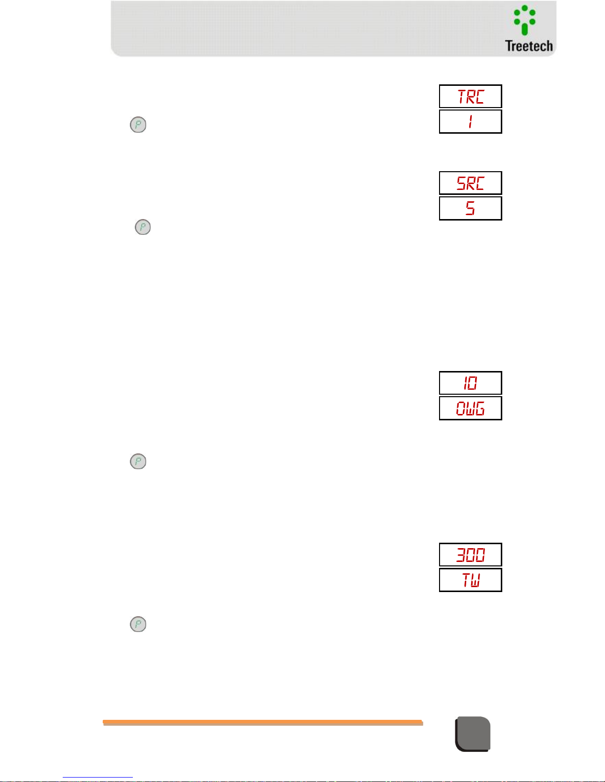
Technical Manual – TM1/TM2 | MA-010| 2016-03-21 | Ver.: 6.30 63
Temperature Monitor
TRC – Rated current for the winding 1 of the transformer whose temperature is
being determined
Adjustment range: 0 to 99,8kA in steps of 0,01 kA.
Press to access parameter SRC
SRC – current in secondary of thermal imaging CT for winding 1, with
transformer under rated load conditions
Formula: SRC = TRC / CT ratio
Adjustment range: 0,5 a 10A in steps of 0,01 A.
Press to acess parameter OWG (wind. 2)
5.3.1.6 Monitor de Temperatura TM2 –Submenu TRF
OWG – Oil/Winding 1 temperature gradient
This value must be informed by the manufacturer of the transformer /
reactor. The figure is obtained by heat run tests or by calculation.
The OWG is defined by IEC 60076-7 as the difference between the average
temperature of the einding and the average temperature of the top oil, after
thermal stability is achieved under rated load conditions.
At NBR 5416 / IEEE C57.91-1995 the OWG is defined as the elevation of the
average temperature of the winding related to the average top oil
temperature, after termal stability is achieved under rated load conditions.
Adjustment range: 0 to 50ºC, in steps of 0,1ºC.
Press to access parameter TW.
TW – Time constant for the winding 1. This is the the time constant in seconds,
relative.
This is the time constant in seconds, relative to the thermal inertia of the
transformer’s winding 1.
This parameter can be measured during the transformer heat run test or
calculated by the manufacturer of the transformer. In case it cannot be
obtained either way, the typical value of 300 s can be adopted.
Adjustment Range: 72 to 999, in steps 1.
Press to access parameter HS+.
Page 64
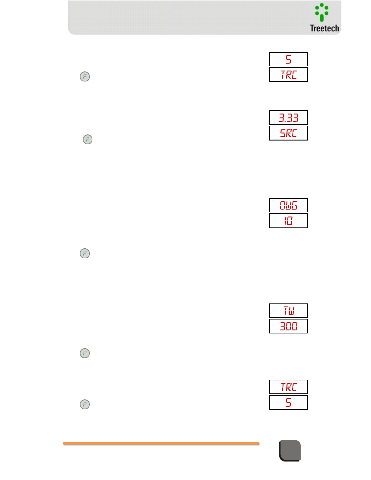
Technical Manual – TM1/TM2 | MA-010| 2016-03-21 | Ver.: 6.30 64
Temperature Monitor
TRC – Rated current for the winding 1 of the transformer whose temperature is
being determined
Adjustment range: 0 to 99,8kA in steps of 0,01 kA.
Press to access parameter SRC
SRC – current in secondary of thermal imaging CT for winding 1, with
transformer under rated load conditions
Formula: SRC = TRC / CT ratio
Adjustment range: 0,5 to 10A in steps of 0,01 A.
Press to acess parameter OWG (wind. 2)
OWG – Oil/Winding 1 temperature gradient
This value must be informed by the manufacturer of the transformer /
reactor. The figure is obtained by heat run tests or by calculation.
The OWG is defined by IEC 60076-7 as the difference between the average
temperature of the einding and the average temperature of the top oil, after
thermal stability is achieved under rated load conditions.
At NBR 5416 / IEEE C57.91-1995 the OWG is defined as the elevation of the
average temperature of the winding related to the average top oil
temperature, after termal stability is achieved under rated load conditions.
Adjustment range: 0 to 50ºC, in steps of 0,1ºC.
Press to access parameter TW.
TW – Time constant for the winding 1. This is the the time constant in seconds,
relative.
This is the time constant in seconds, relative to the thermal inertia of the
transformer’s winding 1.
This parameter can be measured during the transformer heat run test or
calculated by the manufacturer of the transformer. In case it cannot be
obtained either way, the typical value of 300 s can be adopted.
Adjustment Range: 72 to 999, in steps 1.
Press to access parameter HS+.
TRC – Rated current for the winding 1 of the transformer whose temperature is
being determined
Adjustment range: 0 to 99,8kA in steps of 0,01 kA.
Press to access parameter SRC
Page 65
Technical Manual – TM1/TM2 | MA-010| 2016-03-21 | Ver.: 6.30 65
Temperature Monitor
SRC – current in secondary of thermal imaging CT for winding 1, with
transformer under rated load conditions
Formula: SRC = TRC / CT ratio
Adjustment range: 0,5 to 10A in steps de 0,01 A.
Press to acess parameter OWG (wind. 2)
Submenu FAN
It allows access to the parameters referring to the configurations of forced cooling
operation. These parameters are adjusted in TM1 only. Adjustments are carried out
only on TM1. Some special functions for control of the cooling equipment (fans and/or
pumps) are optional.
Cooling operation adjustments are subdivided in some additional submenus showed
below.
With the display showing mnu / FAN, press key to obtain access to forced cooling
setup or;
Press the key to go to the menu mnu / DTC (if the optional for temperature
differential is available) or mnu / LOG (if the optional for mass memory is available) or
press to return to the menu mnu / TRF
5.3.1.7 Submenu CNF
It contains the general configuration parameters of Forced Cooling
NCG – Total number of forced cooling groups
In case only the Temperature Monitor TM1 is used, two output contacts are
available for cooling command, then NCG parameter will allow an 1 to 2
adjustment range.
In case TM1 and TM2 are used, four contacts will be available and the
parameter will have 1 to 4 adjustment range. In this case, it is possible to use
the TM2 cooling command contacts as redundancy for TM1 contacts, simply
setting the number of groups NCG to 2.
Press key to proceed to HYS parameter
Page 66
Technical Manual – TM1/TM2 | MA-010| 2016-03-21 | Ver.: 6.30 66
Temperature Monitor
HYS – Difference between the start and stop temperature of fans/pumps
HYS parameter (hysteresis) sets a value for temperature reduction below the
cooling start temperature to deactivate fans/pumps, thus preventing they
are activated and subsequently deactivated with small temperature
fluctuations
Faixa de ajuste: 0 a 9 ºC; in steps of 1 ºC.
Press to access parameter HYL.
HYL – It is the difference between the load percentage to start and stop
fans/pumps
Load hysteresis parameter (HYL) sets a value for load percentage reduction
below the cooling start load to deactivate fans/pumps, thus preventing they
are activated and subsequently deactivated with small load fluctuations.
This parameter will only be shown in case the Temperature Monitor features
the optional Pre-Cooling function.
Adjustment range: 0 to 9%, in steps of 1%
Press to access parameter FEH
FEH – Start time of Fans/Pumps Exercise
Adjust the time in which the forced cooling groups have to be activated for
the daily exercise of fans/pumps.
This parameter will only be shown in case the Temperature Monitor features
the optional Cooling Exercise function.
Adjustment Range: 0 to 23, by 1 hour.
Press to access parameter FEM
FEM – Start minute of Fans/Pumps Exercise
Adjust supplementary time (minute) in which the forced cooling groups have
to be activated for the daily exercise of fans or pumps.
This parameter will only be shown in case the Temperature Monitor features
the optional Cooling Exercise function.
Adjustment range: 0 to 59 minutes, in steps of 1 minute.
Press to access parameter TFE
Page 67
Technical Manual – TM1/TM2 | MA-010| 2016-03-21 | Ver.: 6.30 67
Temperature Monitor
TFE – Time of fans Exercise
Adjust total daily time the forced cooling groups have to remain activated for
the exercise of fans or pumps. In case Cooling Exercise function needs to be
deactivated, simply set this parameter to zero.
This parameter will only be shown in case the Temperature Monitor features
the optional Cooling Exercise function.
Adjustment range: 0 to 999 minutes, in steps of 1 minute.
Press or to return to submenu FAN.
5.3.1.8 Submenus CS1, CS2, CS3, CS4
CS1, CS2, CS3 and CS4 submenus allow to adjust the operation parameters of forced Cooling
Stages 1 to 4, respectively. Basically, each submenu has the same parameters, as shown below.
FC1 / FC2 / FC3 / FC4 – Activation temperature of the 1st / 2nd / 3rd / 4th
Forced Cooling Stage
When the temperature of one of the transformer windings reaches the set
value, one of the Cooling Groups enrolled in the corresponding Cooling Stage
(selected as "YES" in CG1, CG2, CG3 and CG4 parameters of each Stage) will
be activated.
Adjustment range: -55 to 200ºC, in steps of 1ºC
Press to access parameters LC1 / LC2 / LC3 / LC4.
LC1 / LC2 / LC3 / LC4 – Percentage of Load to activate the 1st / 2nd / 3rd / 4th
Forced Cooling Stage
When the load percentage of one of the transformer windings reaches the
set value, one of the Cooling Groups enrolled in the corresponding Cooling
Stage (selected as "YES" in CG1, CG2, CG3 and CG4 parameters of each
Stage) will be activated.
Adjustment range: 50 to 200%, in steps 1%
Press to access parameter CG1.
Page 68
Technical Manual – TM1/TM2 | MA-010| 2016-03-21 | Ver.: 6.30 68
Temperature Monitor
CG1 – Enrollment of Cooling Group 1 in the 1st / 2nd / 3rd / 4th Forced Cooling
Stage
It allows to select if Cooling Group 1 will be enrolled in the 1st / 2nd / 3rd /
4th Forced Cooling Stage or not, that is, if it can be considered as available or
not to be used by the Cooling Stage when its activation temperature or load
percentage is reached.
Adjustment range: YES or NO
Press to access parameter CG2.
CG2 – Enrollment of Cooling Group 2 in the 1st / 2nd / 3rd / 4th Forced Cooling
Stage
It allows to select if Cooling Group 2 will be enrolled in the 1st / 2nd / 3rd /
4th Forced Cooling Stage or not, that is, if it can be considered as available or
not to be used by the Cooling Stage when its activation temperature or load
percentage is reached.
Adjustment range: YES or NO
Press to access parameter CG3.
CG3 – Enrollment of Cooling Group 3 in the 1st / 2nd / 3rd / 4th Forced Cooling
Stage
It allows to select if Cooling Group 3 will be enrolled in the 1st / 2nd / 3rd /
4th Forced Cooling Stage or not, that is, if it can be considered as available or
not to be used by the Cooling Stage when its activation temperature or load
percentage is reached.
Adjustment range: YES or NO
Press to access parameter CG4.
CG4 – Enrollment of Cooling Group 4 in the 1st / 2nd / 3rd / 4th Forced Cooling
Stage
It allows to select if Cooling Group 4 will be enrolled in the 1st / 2nd / 3rd /
4th Forced Cooling Stage or not, that is, if it can be considered as available or
not to be used by the Cooling Stage when its activation temperature or load
percentage is reached.
Adjustment range: YES or NO
Press key or to return to FAN submenu.
Page 69
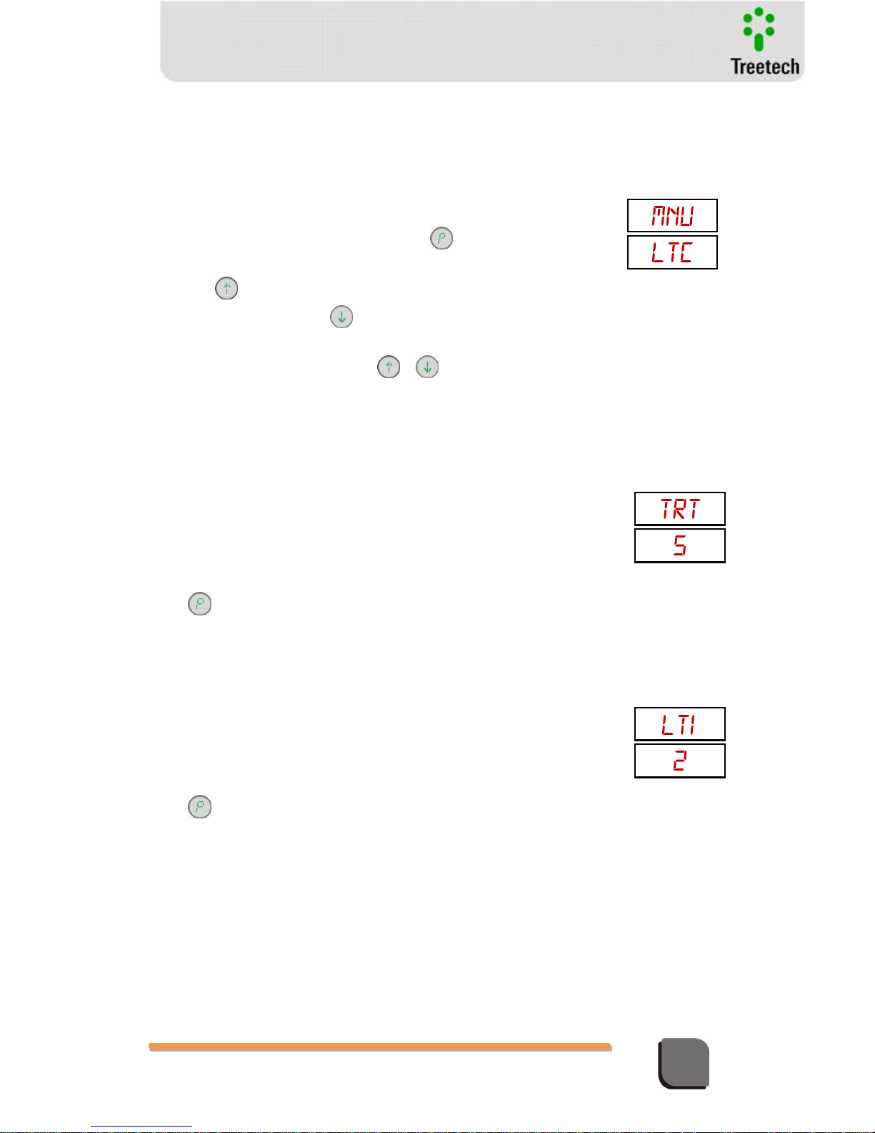
Technical Manual – TM1/TM2 | MA-010| 2016-03-21 | Ver.: 6.30 69
Temperature Monitor
Submenu LTC (optional)
It allows access to the parameters referring to the monitoring of Load Tap
Changer temperature differential. This submenu will only be shown if this
optional monitoring function is available. These parameters are adjusted in
TM1 only.
With the display showing mnu / LTC, press key to obtain access to
temperature differential setup or;
Press the key to go to the menu mnu / LOG (if the optional for mass
memory is available) or press to return to the menu mnu / FAN.
Em cada parâmetro, utilizar as teclas e para ajustar o valor desejado.
TRT – Selection of transformer oil temperature sensor used for differential
calculation
Adjustment range:
1 – Sensor RTD A of TM1
2 – Sensor RTD B of TM1
3 – Sensor RTD A of TM2
4 – Sensor RTD B of TM2
5 – Top oil temperature
Press to access parameter LT1
LT1 - Selection of LTC 1 temperature sensor
Adjustment range:
0 – None (temperature differential of LTC 1 not used)
1 – Sensor RTD A of TM1
2 – Sensor RTD B of TM1
3 – Sensor RTD A of TM2
4 – Sensor RTD B of TM2
Press to access parameter LT2
Page 70
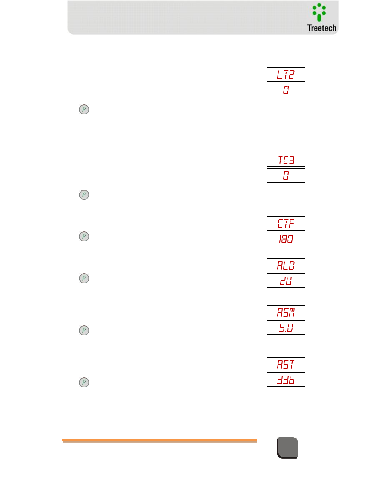
Technical Manual – TM1/TM2 | MA-010| 2016-03-21 | Ver.: 6.30 70
Temperature Monitor
LT2 - Selection of LTC 2 temperature sensor
Adjustment range:
0 – None (temperature differential of LTC 1 not used)
1 – Sensor RTD A of TM1
2 – Sensor RTD B of TM1
3 – Sensor RTD A of TM2
4 – Sensor RTD B of TM2
Press to access parameter LT3
LT3 - Selection of LTC 3 temperature sensor
Adjustment range:
0 – None (temperature differential of LTC 1 not used)
1 – Sensor RTD A of TM1
2 – Sensor RTD B of TM1
3 – Sensor RTD A of TM2
4 – Sensor RTD B of TM2
Press to access parameter FTC
FTC – Filtering time-constant for the LTC temperature differentials
Adjustment range: 0 to 720 minutes, in steps of 1 minute.
Press to access parameter ALD
ALD – Alarm time delay for LTC temperature differentials
Adjustment range: 0 to 240 minutes, in steps of 1 minute.
Press to access parameter ASM
ASM – Temperature margin for automatic alarm settings for LTC temperature
differentials
Adjustment range: 1 to 10ºC, in steps of 1ºC
Press to access parameter AST
AST – Total Time For Automatic Alarm Settings For LTC Temperature
Differentials
Adjustment range: 1 to 720 horas, in steps of 1 hour.
Press to access parameter AAS
Page 71
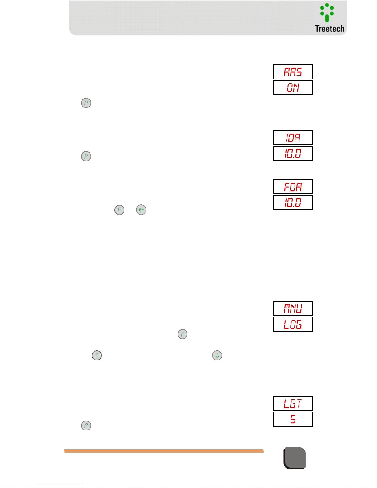
Technical Manual – TM1/TM2 | MA-010| 2016-03-21 | Ver.: 6.30 71
Temperature Monitor
AAS – Automatic Alarm Settings For LTC Temperature Differentials
It allows starting (ON) or stopping (OFF) the process for automatic alarm
settings of instantaneous and filtered LTC temperature differentials.
By selecting ON the time countdown for automatic learning of settings will
start with the value programmed in the parameter AST above.
Adjustment range: ON or OFF.
Press to access IDA
IDA – Instantaneous Differential Alarm For Ltcs (consultation or manual
adjustment)
Adjustment range: -40 to +40ºC, in steps of 0,1ºC
Press to access parameter FDA
FDA – Alarme por Diferencial de Temperatura Filtrado dos Comutadores Sob
Carga
Faixa de ajuste: -40 a +40ºC, em passos de 0,1ºC
Pressionar a tecla ou para retornar ao menu principal.
Submenu LOG (optional)
It allows adjustment of the parameters that define the recording of
measurements and events in the mass memory. This submenu will only be
shown if this optional function is available. These parameters are adjusted in
TM1 only. The mass memory is type FIFO (First In First Out), that is, when the
end of the memory is reached oldest data are overwritten by newer ones. A
new recording in memory can be triggered based on a time interval or a
temperature change greater than the adjusted value, as well as by the
occurrence of any event (alarm, trip or forced cooling activation).
With the display showing mnu / Log, press key to obtain access to mass
memory setup or;
Press the key to go to the menu mnu / fab or press to return to the
menu mnu / DTC or fan.
LGT – Time interval to perform a new recording in memory
It establishes the time interval to perform a new recording in the mass
memory, in minutes.
Adjustment range: 1 to 120 minutos, in steps of 1 minute.
Press to access parameter LGH
Page 72
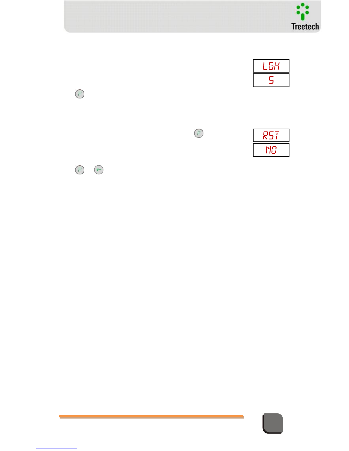
Technical Manual – TM1/TM2 | MA-010| 2016-03-21 | Ver.: 6.30 72
Temperature Monitor
LGH – Temperature variation to perform a new recording in memory
It establishes the time interval to perform a new recording in the mass
memory, in minutes. This resource allows to extend the time so that the
oldest data memory to be overwritten, preventing recordings if the
measurements do not vary significantly.
Adjustment range: 1 to 20ºC, in steps of 1ºC.
Press to access parameter RST
RST – Memory reset command
It allows the restart of the mass memory by erasing all the stored data. User
must confirm this option by selecting YES and pressing key. This process
may take several seconds; during this time the display will keep the message
RST / YES.
Adjustment range: NO or YES.
Press or to return to main menu.
Page 73
Technical Manual – TM1/TM2 | MA-010| 2016-03-21 | Ver.: 6.30 73
Temperature Monitor
5.4 Typical adjusts
Standard / Temperature Rise
ABNT
ANSI
IEC
55 ºC
65 ºC
55 ºC
65 ºC
55 ºC
65 ºC
TW – Time Constant of the winding
300
2*M – Exponent of the winding
1.6 for natural and forced (non-directed) oil
2.0 for directed oil
HS+ ANSI / ABNT (ºC) hot spot factor
10
15
10
15 0 HS* IEC hot spot factor
1.0
1.3
FC1…FC4 – Start up temperature for cooling
stages 1 to 4
According to transformer manufacturer
instructions
OAL – Oil temperature alarm
95 ºC
WAL – Winding temperature alarm (ºC)
105 ºC
OTP – Oil trip temperature (ºC)
110 ºC
WTP – Winding trip temperature (ºC)
120 ºC
OTD and WTD – Trip delay (minutes)
2
HYS – Hysteresis (ºC)
4...6
SUP –Supervision mode
SUP = 0 TM1
SUP = 1 TM1 + TM2
SUP = 4 TM1 + MT2
SUP = 5 TM1 + IRIG-B
ADR – Address of TM1 and TM2 in the
communication networks.
TM1: ADR = 1 to 31 (device’s address on the
communication network for data acquisition)
TM2 / MT2: ADR = 1 (device’s address for
communication with TM1)
Page 74

Technical Manual – TM1/TM2 | MA-010| 2016-03-21 | Ver.: 6.30 74
Temperature Monitor
6 Start-up procedure for puttin equipment in operation
Once the equipment has been installed, putting the equipment in operation must follow
the basic steps described below
Make sure that no operation of contacts will interfere or interact with other systems,
during this phase. Remove the lower connectors (terminals 1...A4) of TM1 and TM2, this
way insulating all the command, alarm and trip contacts.
Check electrical installation. Check suitability of electrical wiring (for example, through
continuity testing).
Make sure that no current transformer (CT) secondary will be open during installation and
operation of the temperature monitors. Short-circuit and ground CT secondaries that will
be connected to the temperature monitors before undertaking any operation if the
transformer is energized during installation of TM1 and TM2. After installation is
completed, carry out detailed and careful check of this wiring before removing the shortcircuit from the secondaries.
If dielectric rigidity tests are carried out on the wiring (applied voltage), disconnect
grounding cables connected to terminals 13 of TM1 and TM2 in order to prevent
destruction of over-voltage protection equipment found in the device. These protections
are connected internally between input/output terminals and ground, stapling voltage at
about 300V. Application of high voltages for long periods of time (for example, 2kV for 1
minute) would destroy this protection.
Reconnect ground cable to terminals 13 of TM1 and TM2, if it was disconnected for the
applied voltage test. Energize TM1 and TM2 with any voltage in the 38 to 265Vdc/Vac
50/60Hz range.
Perform all the necessary parameter definitions for the TM1 and TM2. The parameter
settings performed can be written down in the form of the next page.
Connect a temperature calibrator, resistive decade or check the temperature of Pt100
sensors connected to TM1 to check the measurements.
Inject ac current in the CT inputs of TM1 and TM2 or measure the current of the bushing
CT circuit and check it on the TM’s consultation screens.
Using dc miliamp meter, check current loop outputs with the corresponding temperatures
measured.
With a continuity detection device, test action of alarm, trip and forced cooling contacts.
Contacts can be activated by reducing alarm set values to lower values than those for
current readings.
Reconnect the lower connector (1...A4) of TM1 and TM2 if they were removed for start-up.
Page 75
Technical Manual – TM1/TM2 | MA-010| 2016-03-21 | Ver.: 6.30 75
Temperature Monitor
Temperature Monitor TM1 – Parameter Settings
Serial
No.:
Date:
Responsible:
Subme
nu
Paramet
er
Description
Value Set
ALM
OAL
Oil alarm temperature
ºC
OTP
Oil trip temperature
ºC
OTD
Oil trip delay
min
WAL
Winding 1 alarm temperature
ºC
WTP
Winding 1 trip temperature
ºC
WTD
Winding 1 trip delay
min
CNF
AOR
Analog output range
AV1
(op.)
Variable associated to Analog Output 1
FE1
Analog output 1 end-of-scale
ºC
IE1
Analog output 1 beginning-of-scale
ºC
AV2
(op.)
Variable associated to Analog Output 2
FE2
Analog output 2 end-of-scale
ºC
IE2
Analog output 2 beginning-of-scale
ºC
RL7 (op.)
Signaling function of Output Relay 7
RTD
Connection option for temperature
sensors
SML
Pt100 input check by way of electronic
RTD simulator
MDT
Maximum temp. difference (option RTD
2x3)
COM
Serial communication port used
BDR
Serial communication baud-rate
bps
ADR
Serial communication address
PRT
(op.)
Communication protocol
SUP
Supervision mode
NPW
New menu access password
TRF /
ALL
OWG
Oil-winding 1 temperature gradient
ºC
TW
Winding 1 time-constant
sec.
HS+
Hot-spot factor by ANSI and ABNT
standards
ºC
HS*
Hot-spot factor by IEC standard
2*M
Exponent defined by type of cooling
TRC
Rated current of winding 1
kA
SRC
Winding 1 CT secondary current at rated
load
A
Page 76
Technical Manual – TM1/TM2 | MA-010| 2016-03-21 | Ver.: 6.30 76
Temperature Monitor
TRF /
CS0
OWG
Oil-winding 1 temperature gradient
ºC
TW
Winding 1 time-constant
sec.
HS+
Hot-spot factor by ANSI and ABNT
standards
ºC
HS*
Hot-spot factor by IEC standard
2*M
Exponent defined by type of cooling
TRC
Rated current of winding 1
kA
SRC
Winding 1 CT secondary current at rated
load
A
TRF /
CS1
OWG
Oil-winding 1 temperature gradient
ºC
TW
Winding 1 time-constant
sec.
HS+
Hot-spot factor by ANSI and ABNT
standards
ºC
HS*
Hot-spot factor by IEC standard
2*M
Exponent defined by type of cooling
TRC
Rated current of winding 1
kA
SRC
Winding 1 CT secondary current at rated
load
A
TRF /
CS2
OWG
Oil-winding 1 temperature gradient
ºC
TW
Winding 1 time-constant
sec.
HS+
Hot-spot factor by ANSI and ABNT
standards
ºC
HS*
Hot-spot factor by IEC standard
2*M
Exponent defined by type of cooling
TRC
Rated current of winding 1
kA
SRC
Winding 1 CT secondary current at rated
load
A
TRF /
CS3
OWG
Oil-winding 1 temperature gradient
ºC
TW
Winding 1 time-constant
sec.
HS+
Hot-spot factor by ANSI and ABNT
standards
ºC
HS*
Hot-spot factor by IEC standard
2*M
Exponent defined by type of cooling
TRC
Rated current of winding 1
kA
SRC
Winding 1 CT secondary current at rated
load
A
TRF /
CS4
OWG
Oil-winding 1 temperature gradient
ºC
TW
Winding 1 time-constant
sec.
HS+
Hot-spot factor by ANSI and ABNT
standards
ºC
HS*
Hot-spot factor by IEC standard
2*M
Exponent defined by type of cooling
TRC
Rated current of winding 1
kA
SRC
Winding 1 CT secondary current at rated
A
Page 77
Technical Manual – TM1/TM2 | MA-010| 2016-03-21 | Ver.: 6.30 77
Temperature Monitor
load
FAN /
CNF
NCG
Total number of cooling groups
HYS
Hysteresis for turning off cooling groups
ºC
HYL (op.)
Load hysteresis for turning off cooling
groups
%
FEH
(op.)
Set hour to turn on cooling groups
hour
FEM
(op.)
Set minute to turn on cooling groups
min.
TFE (op.)
Total cooling operation time
min.
Subme
nu
Paramet
er
Description
Value Set
FAN /
CS1
FC1
Operation temperature of cooling stage 1
ºC
SCT
Stage Control Temperature
Oil/Wid
LC1 (op.)
Percent load for turning on cooling stage 1
%
CG1
Registration of Cooling Group 1 for Stage 1
CG2
Registration of Cooling Group 2 for Stage 1
CG3
Registration of Cooling Group 3 for Stage 1
CG4
Registration of Cooling Group 4 for Stage 1
FAN /
CS2
FC2
Operation temperature of cooling stage 2
ºC
SCT
Stage Control Temperature
Oil/Wid
LC2 (op.)
Percent load for turning on cooling stage 2
% CG1
Registration of Cooling Group 1 for Stage 2
CG2
Registration of Cooling Group 2 for Stage 2
CG3
Registration of Cooling Group 3 for Stage 2
CG4
Registration of Cooling Group 4 for Stage 2
FAN /
CS3
FC3
Operation temperature of cooling stage 3
ºC
SCT
Stage Control Temperature
Oil/Wid
LC3 (op.)
Percent load for turning on cooling stage 3
% CG1
Registration of Cooling Group 1 for Stage 3
CG2
Registration of Cooling Group 2 for Stage 3
CG3
Registration of Cooling Group 3 for Stage 3
CG4
Registration of Cooling Group 4 for Stage 3
FAN /
CS4
FC4
Operation temperature of cooling stage 4
ºC
SCT
Stage Control Temperature
Oil/Wid
LC4 (op.)
Percent load for turning on cooling stage 4
% CG1
Registration of Cooling Group 1 for Stage 4
CG2
Registration of Cooling Group 2 for Stage 4
CG3
Registration of Cooling Group 3 for Stage 4
CG4
Registration of Cooling Group 4 for Stage 4
LTC
(op.)
TRT
Selection of transformer temperature
sensor
LT1
Selection of LTC 1 temperature sensor
Page 78
Technical Manual – TM1/TM2 | MA-010| 2016-03-21 | Ver.: 6.30 78
Temperature Monitor
LT2
Selection of LTC 2 temperature sensor
LT3
Selection of LTC 3 temperature sensor
FTC
Filter time-constant for temperature
differential
min.
ALD
Alarm delay for LTC temperature
differential
min.
ASM
Margin for automatic differential alarm
settings
ºC
AST
Learning time for automatic alarm settings
hours
AAS
Automatic Alarm Settings For LTC
IDA
Instantaneous LTC differential alarm
ºC
FDA
Filtered LTC differential alarm
ºC
LOG
(op.)
LGT
Time interval for mass memory recording
min.
LGH
Temperature variation for memory
recording
ºC
RST
Memory reset command
Temperature Monitor TM2 – Parameter Settings
Serial
No.:
Date:
Responsible:
Subme
nu
Paramet
er
Description
Value Set
ALM
WAL (2)
Winding 2 alarm temperature
ºC
WTP (2)
Winding 2 trip temperature
ºC
WTD (2)
Winding 2 trip delay
min
WAL (3)
Winding 3 alarm temperature
ºC
WTP (3)
Winding 3 trip temperature
ºC
WTD (3)
Winding 3 trip delay
min
CNF
AOR
Analog output range
AV1
(op.)
Variable associated to Analog Output 1
FE1
Analog output 1 end-of-scale
ºC
IE1
Analog output 1 beginning-of-scale
ºC
AV2
(op.)
Variable associated to Analog Output 2
FE2
Analog output 2 end-of-scale
ºC
IE2
Analog output 2 beginning-of-scale
ºC
RL7 (op.)
Signaling function of Output Relay 7
ADR
Address for communication with TM1
RTD
Connection option for temperature
sensors
NPW
New menu access password
TRF
OWG (2)
Oil-winding 2 temperature gradient
ºC
TW (2)
Winding 2 time-constant
sec.
Page 79
Technical Manual – TM1/TM2 | MA-010| 2016-03-21 | Ver.: 6.30 79
Temperature Monitor
TRC (2)
Rated current of winding 2
kA
SRC (2)
Winding 2 CT secondary current at rated
load
A
OWG (3)
Oil-winding 3 temperature gradient
ºC
TW (3)
Winding 3 time-constant
sec.
TRC (3)
Rated current of winding 3
kA
SRC (3)
Winding 3 CT secondary current at rated
load
A
Page 80
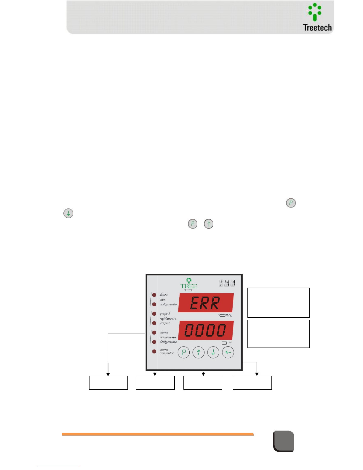
Technical Manual – TM1/TM2 | MA-010| 2016-03-21 | Ver.: 6.30 80
Temperature Monitor
7 Troubleshooting
The Temperature Monitor’s software constantly checks the integrity of its functions and of the
sensors and modules connected to it. Any abnormality is checked, and when verified it is
signaled through its failure contact. Messages will be displayed on the TMs, helping in the
failure diagnosis process.
In case problems are found or difficulties faced in operating the system, we suggest consulting
the possible simple causes and solutions presented below. If this information is not sufficient
to solve the difficulty, please contact Treetech’s technical assistance service or any of its
authorized representatives.
7.1 The device displays self-diagnosis messages on the display
The self-diagnostic function implemented in the Temperature Monitors TM1 and TM2 allows
detection and diagnosis of any eventual external defects or even internal failures of the
equipment, in most cases allowing users to identify and correct problems quickly.
To access the internal error memory of TM1/TM2, press and hold for a few seconds the e
keys. All errors that have been occurred will be shown in superposition, and to clean this
memory, press and hold for a while the segundos e keys.
When a problem is detected, the TM1 or TM2 will show the abbreviation “ERR” on the upper
display, while the lower one will show the code for the failure that is occurring. The meaning
for the different codes is shown in the tables below, respected the digit of the display in which
the code appears.
Digit 1
Digit 2
Digit 3
Digit 4
Upper display:
Indication that there
is an active error
Lower display:
Indication of active
error code
Figure 27 – Self-diagnostic indications
Page 81
Technical Manual – TM1/TM2 | MA-010| 2016-03-21 | Ver.: 6.30 81
Temperature Monitor
Table 5 – Digit 1 failures
Digit 1
Code
displayed
Description
Probable causes
Actions recommended
0
No failure in
this digit.
-
-
1
Failure in
measuring
temperature of
sensor A –
sudden change,
in excess of 5°C,
between
consecutive
temperature
measurements
Bad contact or
disconnection in one of the
cables connected to
terminals 1 and/or 2 of the
temperature sensor A.
Check for bad contact or disconnection
along the entire length of the cables
connected to terminals 1 and 2 of the
temperature sensor A, including the
connection to TM, to passage terminals and
to the sensor.
Use of unshielded cable
in connection between
sensor Pt100 and TM.
Make sure that shielded cable is being
used to connect Pt100 sensor A to the
temperature monitor.
Cables connecting Pt 100
sensor to TM not grounded
or grounded in more than
one point.
Make sure shielding of connection cable
between TM and temperature sensor A is
grounded only on one side of the connection
and that the other end is insulated, as per
figure 4.3, page II-6.
Internal failure in
temperature sensor A.
Replace defective temperature sensor A.
After checking and correcting cause of failure in reading, reset the error
by pressing and holding the keys and . ATTENTION: in resetting, the
TM is informed that the current value of the temperature reading is correct.
If the device is reset with an incorrect temperature reading, this may trigger
incorrect alarm, for instance due to LTC temperature differential.
2
Failure in
measuring
temperature of
sensor B –
sudden change,
in excess of 5°C,
between
consecutive
temperature
measurements
Bad contact or
disconnection in one of the
cables connected to
terminals 1 and/or 2 of the
temperature sensor B.
Check for bad contact or disconnection
along the entire length of the cables
connected to terminals 1 and 2 of the
temperature sensor B, including the
connection to TM, to passage terminals and
to the sensor.
Use of unshielded cable
in connection between
sensor Pt100 and TM.
Make sure that shielded cable is being
used to connect Pt100 sensor B to the
temperature monitor.
Cables connecting Pt 100
sensor to TM not grounded
or grounded in more than
one point.
Make sure shielding of connection cable
between TM and temperature sensor B is
grounded only on one side of the connection
and that the other end is insulated, as per
figure 4.3, page II-6.
Internal failure in
temperature sensor B.
Replace defective temperature sensor B.
After checking and correcting cause of failure in reading, reset the error
by pressing and holding the keys and . ATTENTION: in resetting, the
TM is informed that the current value of the temperature reading is correct.
If the device is reset with an incorrect temperature reading, this may trigger
incorrect alarm, for instance due to LTC temperature differential.
3
Simultaneou
s occurrence of
codes 1 and 2
above
see codes 1 and 2
above.
Proceed as indicated for codes 1 and 2
above
Page 82
Technical Manual – TM1/TM2 | MA-010| 2016-03-21 | Ver.: 6.30 82
Temperature Monitor
Table 6 – Digit 2 Failures
Digit 2
Code
displayed
Description
Probable causes
Actions recommended
0
No failure
in this digit.
-
-
1
Failure in
measuring
temperature
sensor A.
Sensor A is not in use,
but its reading is
enabled in parameter
RTD.
Disable reading of sensor not used by
changing the parameter RTD.
Bad contact on cable
connected to terminal 1
of the temperature
sensor A.
Check for bad contact along the entire
length of the cable connected to terminal 1 of
the temperature sensor A, including the
connection to TM, to passage terminals and
to the sensor.
Internal failure in
temperature sensor A.
Replace defective temperature sensor A.
2
Failure in
measuring
temperature
sensor B.
Sensor B is not in use,
but its reading is
enabled in parameter
RTD.
Disable reading of sensor not used by
changing the parameter RTD.
Bad contact on cable
connected to terminal 1
of the temperature
sensor B.
Check for bad contact along the entire
length of the cable connected to terminal 1 of
the temperature sensor B, including the
connection to TM, to passage terminals and
to the sensor.
Internal failure in
temperature sensor B.
Replace defective temperature sensor B.
3
Simultane
ous
occurrence of
codes 1 and 2
above
see codes 1 and 2
above.
Proceed as indicated for codes 1 and 2
above
4
Failure in
measuring
temperature
sensor A.
Sensor A is not in use,
but its reading is
enabled in parameter
RTD.
Disable reading of sensor not used by
changing the parameter RTD.
Bad contact on cable
connected to terminal 2
of the temperature
sensor A.
Check for bad contact along the entire
length of the cable connected to terminal 2 of
the temperature sensor A, including the
connection to TM, to passage terminals and
to the sensor.
Internal failure in
temperature sensor A.
Replace defective temperature sensor A.
5
Simultane
ous
occurrence of
codes 1 and 4
above
see codes 1 and 4
above.
Proceed as indicated for codes 1 and 4
above
6
Simultane
ous
occurrence of
codes 2 and 4
above
see codes 2 and 4
above.
Proceed as indicated for codes 2 and 4
above
Page 83
Technical Manual – TM1/TM2 | MA-010| 2016-03-21 | Ver.: 6.30 83
Temperature Monitor
7
Simultane
ous
occurrence of
codes 1, 2
and 4 above
see codes 1, 2 and 4
above.
Proceed as indicated for codes 1, 2 and 4
above
8
Failure in
measuring
temperature
sensor B.
Sensor B is not in use,
but its reading is
enabled in parameter
RTD.
Disable reading of sensor not used by
changing the parameter RTD.
Bad contact on cable
connected to terminal 2
of the temperature
sensor B.
Check for bad contact along the entire
length of the cable connected to terminal 2 of
the temperature sensor B, including the
connection to TM, to passage terminals and to
the sensor.
Internal failure in
temperature sensor B.
Replace defective temperature sensor B.
9
Simultane
ous
occurrence of
codes 1 and 8
above
see codes 1 and 8
above.
Proceed as indicated for codes 1 and 8
above
A
Simultane
ous
occurrence of
codes 2 and 8
above
see codes 2 and 8
above.
Proceed as indicated for codes 2 and 8
above
B
Simultane
ous
occurrence of
codes 1, 2
and 8 above
see codes 1, 2 and 8
above.
Proceed as indicated for codes 1, 2 and 8
above
C
Simultane
ous
occurrence of
codes 4 and 8
above
see codes 4 and 8
above.
Proceed as indicated for codes 4 and 8
above
D
Simultane
ous
occurrence of
codes 1, 4
and 8 above
see codes 1, 4 and 8
above.
Proceed as indicated for codes 1, 4 and 8
above
E
Simultane
ous
occurrence of
codes 2, 4
and 8 above
see codes 2, 4 and 8
above.
Proceed as indicated for codes 2, 4 and 8
above
F
Simultane
ous
occurrence of
codes 1, 2, 4
and 8 above
see codes 1, 2, 4 and
8 above.
Proceed as indicated for codes 1, 2, 4 and
8 above
Page 84
Technical Manual – TM1/TM2 | MA-010| 2016-03-21 | Ver.: 6.30 84
Temperature Monitor
Table 7 – Digit 3 Failures
Digit 3
Code
displayed
Description
Probable causes
Actions recommended
0
No failure
in this digit.
-
-
1
Failure in
measuring
temperature –
sudden
change, in
excess of 5°C,
between
consecutive
temperature
measurements
or high
temperature
difference
between
sensors A and
B.
The parameter RTD
is programmed with
option 2X3 in TM1, but
only one sensor is being
used for top oil
temperature
measurement.
Revise programming of parameter RTD,
according to the configuration being used
temperature sensors.
Parameter MDT
(Maximum Difference
of Temperature
between top oil
redundant sensors A
and B) programmed too
low in TM1.
Revise programming of parameter RTD, so
as to avoid it to be lower than the normal
temperature difference between top oil
temperature sensors A e B.
Bad contact or
disconnection in one of
the cables connected to
terminals 1 and/or 2 of
the temperature
sensors A and/or B.
Check for bad contact or disconnection
along the entire length of the cables
connected to terminals 1 and 2 of the
temperature sensors A and B, including the
connection to TM, to passage terminals and
to the sensors.
Use of unshielded
cable in connection
between sensors Pt100
and TM.
Make sure that shielded cable is being
used to connect Pt100 sensors to the
temperature monitor.
Cables connecting Pt
100 sensors to TM not
grounded or grounded
in more than one point.
Make sure shielding of connection cables
between TM and sensors Pt100 are grounded
only on one side of the connection and that
the other end is insulated.
Internal failure in
temperature sensors A
and/or B.
Replace defective temperature sensor A
and/or B.
After checking and correcting cause of failure in reading, reset the
error by pressing and holding the keys and of TM1 for about 2
seconds. ATTENTION: in resetting, the TM1 is informed that the current
value of the temperature reading is correct. If the device is reset with an
incorrect, high temperature reading, this may trigger incorrect alarm or
transformer trip events.
2
Internal
Error – AD
Converter
Internal failure of
TM.
Replace defective TM and contact
Treetech Technical Assistance.
3
Simultaneo
us occurrence
of codes 1 and
2 above
see codes 1 and 2
above.
Proceed as indicated for codes 1 and 2
above
4
Failure in
measuring
load current
Internal failure of
TM.
Replace defective TM and contact
Treetech Technical Assistance.
Page 85
Technical Manual – TM1/TM2 | MA-010| 2016-03-21 | Ver.: 6.30 85
Temperature Monitor
5
Simultane
ous
occurrence of
codes 1 and 4
above
see codes 1 and 4
above.
Proceed as indicated for codes 1 and 4
above
6
Simultane
ous
occurrence of
codes 2 and 4
above
see codes 2 and 4
above.
Proceed as indicated for codes 2 and 4
above
7
Simultane
ous
occurrence of
codes 1, 2
and 4 above
see codes 1, 2 and 4
above.
Proceed as indicated for codes 1, 2 and 4
above
8
Failure in
measuring
load current
Internal failure of
TM.
Replace defective TM and contact
Treetech Technical Assistance.
9
Simultane
ous
occurrence of
codes 1 and 8
above
see codes 1 and 8
above.
Proceed as indicated for codes 1 and 8
above
A
Simultane
ous
occurrence of
codes 2 and 8
above
see codes 2 and 8
above.
Proceed as indicated for codes 2 and 8
above
B
Simultane
ous
occurrence of
codes 1, 2
and 8 above
see codes 1, 2 and 8
above.
Proceed as indicated for codes 1, 2 and 8
above
C
Simultane
ous
occurrence of
codes 4 and 8
above
see codes 4 and 8
above.
Proceed as indicated for codes 4 and 8
above
D
Simultane
ous
occurrence of
codes 1, 4
and 8 above
see codes 1, 4 and 8
above.
Proceed as indicated for codes 1, 4 and 8
above
E
Simultane
ous
occurrence of
codes 2, 4
and 8 above
see codes 2, 4 and 8
above.
Proceed as indicated for codes 2, 4 and 8
above
F
Simultane
ous
occurrence of
codes 1, 2, 4
and 8 above
see codes 1, 2, 4 and
8 above.
Proceed as indicated for codes 1, 2, 4 and
8 above
Page 86
Technical Manual – TM1/TM2 | MA-010| 2016-03-21 | Ver.: 6.30 86
Temperature Monitor
Table 8 – Digit 4 failures
Digit 4
Code
displayed
Description
Probable causes
Actions recommended
0
No failure
in this digit.
-
-
1
Communic
ation error
between TM1
and TM2.
Bad contact or
inversion on cables
connected to terminals
16 and/or 17 of TM1
and/or TM2.
Check for bad contact, disconnections or
inversions along the entire length of the cable
connected to terminal 16 and/or 17 of TM1
and/or TM2 Temperature Monitors, including
connection to monitors and passage
terminals.
Use of non-shielded
cable in linking TM1 and
TM2 Temperature
Monitors.
Check for use of shielded cable in linking
TM1 and TM2 Temperature Monitors.
Cable shielding on
cable linking TM1 to
TM2 not grounded or
grounded in more than
one point.
Check shielding on cable linking TM1 to
TM2 is grounded only at one end of the
connection with the other end insulated.
Incorrect
programming for
parameter SUP.
Correct programming for parameter SUP.
Incompatibility
between firmware
versions in deploying a
TM with the old MT line.
TM1 or TM2 Temperature Monitors can
only be connected to the monitors of line MT
with firmware version V2.2 or higher.
2
Incorrect
programming
for parameter
SUP
One of the options
not used (options 2 or 3)
was programmed for
parameter SUP.
Correct programming for parameter SUP,
using one of the valid options (0, 1, 4 or 5),
according to whether TM1 is used alone or
together with TM2.
3
Simultane
ous
occurrence of
codes 1 and 2
above
see codes 1 and 2
above.
Proceed as indicated for codes 1 and 2
above
4
Internal
error –
EEPROM
Memory
Internal failure of
TM.
Replace defective TM and contact
Treetech Technical Assistance.
5
Simultane
ous
occurrence of
codes 1 and 4
above
see codes 1 and 4
above.
Proceed as indicated for codes 1 and 4
above
6
Simultane
ous
occurrence of
codes 2 and 4
above
see codes 2 and 4
above.
Proceed as indicated for codes 2 and 4
above
7
Simultane
ous
occurrence of
codes 1, 2
see codes 1, 2 and 4
above.
Proceed as indicated for codes 1, 2 and 4
above
Page 87
Technical Manual – TM1/TM2 | MA-010| 2016-03-21 | Ver.: 6.30 87
Temperature Monitor
and 4 above
8
Measurem
ent Overflow
Internal failure of
TM.
Replace defective TM and contact
Treetech Technical Assistance.
9
Simultane
ous
occurrence of
codes 1 and 8
above
see codes 1 and 8
above.
Proceed as indicated for codes 1 and 8
above
A
Simultane
ous
occurrence of
codes 2 and 8
above
see codes 2 and 8
above.
Proceed as indicated for codes 2 and 8
above
B
Simultane
ous
occurrence of
codes 1, 2
and 8 above
see codes 1, 2 and 8
above.
Proceed as indicated for codes 1, 2 and 8
above
C
Simultane
ous
occurrence of
codes 4 and 8
above
see codes 4 and 8
above.
Proceed as indicated for codes 4 and 8
above
D
Simultane
ous
occurrence of
codes 1, 4
and 8 above
see codes 1, 4 and 8
above.
Proceed as indicated for codes 1, 4 and 8
above
E
Simultane
ous
occurrence of
codes 2, 4
and 8 above
see codes 2, 4 and 8
above.
Proceed as indicated for codes 2, 4 and 8
above
F
Simultane
ous
occurrence of
codes 1, 2, 4
and 8 above
see codes 1, 2, 4 and
8 above.
Proceed as indicated for codes 1, 2, 4 and
8 above
7.2 TM1/TM2 reads incorrect values for temperatures
Table 9 – Incorrect reading of values for temperatures
Probable causes
Actions recommended
Incorrect programming of
quantity and configuration of
temperature sensors in parameter
RTD.
Check for correct programming of the parameter RTD on
submenu CNF.
Bad-contact or disconnection in
one of the cables connected to
terminals 1 and/or 2 of the
temperature sensors.
Check for bad contact points or disconnections along the
entire length of cables connected to terminals 1 and/or 2 of the
temperature sensor, including connection to TM, passage
terminals and to temperature sensors.
Use of non-shielded cables in
connection between Pt100 sensors
Check whether shielded cables are being used in connecting
temperature sensors to TM.
Page 88
Technical Manual – TM1/TM2 | MA-010| 2016-03-21 | Ver.: 6.30 88
Temperature Monitor
and TM.
Shielding for cables connecting
TM to sensors Pt100 is not grounded
or grounded in more than one place.
Check that cable shielding on cables linking TM to
temperature sensors are grounded in just one end of the
connection and the other end insulated.
Failure of temperature sensor.
Replace defective temperature sensor.
7.3 TM1/TM2 reads incorrectly values for load currents
Table 10 – Incorrectly values for load currents
Probable causes
Actions recommended
CT (Current Transformer)
Secondary short-circuited
Check whether the secondary of the CT is short-circuited.
Check that secondary of CT is properly connected to the
temperature monitor before removing short-circuit, thus
avoiding the secondary of the Ct from running open.
Power of CT exceeded.
Check if load created by wiring of CT secondary causes
maximum power to be exceeded, causing error in readings
(input impedance fort TM can be ignored). Increase cable
gauge to reduce load.
Incorrectly programmed rated
current for transformer winding for
parameter TRC.
Correct programming for parameter TRC for each winding
monitored.
7.4 TM1/TM2 indicates incorrect values for winding temperatures
Table 11 – Incorrect values for winding temperatures
Probable causes
Actions recommended
Error in measuring CT secondary current for
CT connected to the Temperature Monitors.
Proceed as in item 7.3 above.
Not all inputs for AC current measurement
are used.
It is normal that, for unused current inputs, the
temperature for the corresponding winding shown is
the same as for temperature of the oil.
Incorrect programming of one or more of the
following parameters: OWG, TW, HS+, HS*, 2*M
e SRC.
Check and correct programming for these
parameters for each winding.
7.5 TM1 does not communicate with the data acquisition system
Table 12 – No communication between TM1 and Data Acquisition system
Probable causes
Actions recommended
Incorrect programming of serial
communication parameters on TM1.
Check for correct programming of the following
parameters on submenu CNF:
- Communication port COM
- Baud-rate – parameter BDR
- Address – parameter ADR
Page 89
Technical Manual – TM1/TM2 | MA-010| 2016-03-21 | Ver.: 6.30 89
Temperature Monitor
- Protocol – parameter PRT
Bad-contact, disconnection or inversion
in one of the serial communication cables.
Check for bad contact points, disconnections or
inversions along the entire length of communication
cables, including connection to TM1, passage terminals
and to data acquisition system.
Unshielded cable, shielding without
grounding or incorrectly grounded used in
connection between data acquisition
system and the TM1.
Use shielded cable.
Incorrect type of cable used
Communication cable must be shielded twisted pair
type.
Distance between ends of
communication network superior to 1300
meters
If total circuit length exceeds distance of 1300 meters,
repeater modules or fiber optic cables must be used.
7.6 Remote reading through analog output incorrect
Table 13 – Remote reading through analog output incorrect
Probable causes
Actions recommended
Incorrect programming of current
output parameters
Check programming of the following parameters on
menu CNF:
- Analog Output Range – AOR
- Variable for Analog Output 1 – AV1
- End of scale of output 1 – FE1
- Beginning of scale of output 1 – IE1
- Variable for Analog Output 2 – AV2
- End of scale of output 2 – FE2
- Beginning of scale of output 2 – IE2
Incorrect connection of connection
cable
Check proper connection of cables (polarity, eventual
short circuits, open links or grounding) between TM1 and
TM2 and measuring system.
Maximum load exceeded
Check maximum load for each output standard
selected.
Lack of grounding, grounding
interrupted or cable shield grounded at
both ends of the circuit.
Grounding failure may allow noise and induced
transients to make current lop readings impossible.
Proceed with cable and connections check (passage
terminals) and grounding.
7.7 TM1/TM2 does not correctly activate the forced cooling
Table 14 - Incorrect activate the forced cooling
Probable Causes
Possible Solutions
Incorrect setting of forced cooling
control parameters.
Correct the settings of forced cooling control parameters.
Page 90
Technical Manual – TM1/TM2 | MA-010| 2016-03-21 | Ver.: 6.30 90
Temperature Monitor
8 Attachments
8.1 Attachment A
Technical Data
Supply Voltage:
38 to 265 Vac/Vdc 50/60Hz
Maximum Consumption:
< 8 W
Operating Temperature:
-40 to +85 ºC
Protection Degree:
IP 20
Wire size, except CT inputs:
22 to 12 AWG, 0.3 to 2.5mm2
Wire size - CT inputs:
one or two 16 to 12 AWG, 1.5 to 2.5mm2 using appropriate
ring-type terminal lugs
Mounting:
Built in panel
Analog outputs:
Maximum error:
options (selections) and maximum load:
2 (w/ common positive) for each device (TM1 or TM2)
0.5 % of full scale
0...1 mA, 10k
0...5 mA, 2k
0...10 mA, 1k
0...20 mA, 500
4...20 mA, 500
Relay outputs:
Type and functions (standard):
Maximum switching power:
Maximum switching voltage:
Maximum conduction current:
Potential free contacts
5NO (alarms/trip)+3NC (2 C.G.+1 self-diagnosis) for
each device (TM1 or TM2)
70 W (dc) / 250 VA (ac) non-inductive
250Vdc / 250 Vac
5 A
Direct temperature measurements (for
instance, oil, ambient, LTC):
Sensor:
Measuring range:
Maximum error @ 20ºC:
Deviation by temperature variation:
Connection options for each device (TM1 or
TM2):
Inputs for RTD sensors w/ continuous self-calibration
Pt100@ 0ºC
-55...200ºC
0.4% of full scale
20ppm/ºC
two 3-wire sensors
one 4-wire sensor or
one 3-wire sensor
Winding temperature measurement
Mathematical models applied:
Calculated
IEEE C57.91-1995
EC 354 - 1991
ABNT NBR 5416-1997 (Brazilian standard)
AC measurement input:
Working range:
Maximum error @ 20ºC:
Deviation by temperature variation:
Direct CT measurement or external clip-on CT
0...10 A
0.5% of end of scale (1% with clip-on CT)
50ppm/ºC
Communication protocols (access through
TM1):
Modbus RTU (standard) or
DNP3.0 level 1 (optional)
Serial Communication Ports:
1 RS 485, interconnection TM1/TM2 or IRIG-B
Page 91

Technical Manual – TM1/TM2 | MA-010| 2016-03-21 | Ver.: 6.30 91
Temperature Monitor
1 user selectable RS 485/RS 232, supervision system (at
TM1 only)
Mass Memory (optional):
Recording interval:
Temperature variation for recording:
Capacity:
TM1 without LTC Temperature Differential:
TM1 with LTC Temperature Differential:
TM1+TM2 without LTC Temperature Diff.:
TM1+TM2 with LTC Temperature Diff.:
1 to 120 minutes
1 to 20ºC
1465 registers
948 registers
848 registers
645 registers
8.2 Attachment B
Order Specification
The Temperature Monitors TM1 and TM2 are universal item equipment, with its features being selected by
using the programming menus. These adjustments can be made directly on the device’s front panel or by
way of the serial communication ports RS232 or RS485. The power feed input is universal (38 to 265
Vdc/Vac 50/60Hz).
Therefore, in purchase orders for the equipment only the following need to be informed:
Temperature Monitor TM1 (oil and one winding temperature):
- Quantity;
- Desired optional functions:
o Optional 1 – Communication protocol DNP3.0 level 1 (in addition to Modbus RTU protocol)
o Optional 2 – Pre-cooling
o Optional 3 – Cooling groups Exercising
o Optional 4 – LTC Temperature Differential
- Optional 5 – Mass Memory
- Type of CT connection: standard model for direct CT connection (0-10A) or optional model for
external clip-on CT (clip-on CTs not included, must be ordered separately as optional accessories).
- Physical configuration of each relay individually (NO or NC), in case this is different from the
standard.
Temperature Monitor TM2 (two additional winding temperatures):
- Quantity;
- Type of CT connection: standard model for direct CT connection (0-10A) or optional model for
external clip-on CT (clip-on CTs not included, must be ordered separately as optional accessories).
Page 92
Technical Manual – TM1/TM2 | MA-010| 2016-03-21 | Ver.: 6.30 92
Temperature Monitor
- Physical configuration of each relay individually (NO or NC), in case this is different from the
standard.
Attention: The Temperature Monitor TM2 must operate obligatorily with Temperature Monitor TM1,
and cannot be operated alone.
8.3 Attachment C
Type testing
Surge Immunity (IEC 60255-22-5):
phase-neutral surges:
phase-ground and neutral-ground surges:
1 kV, 5 per polarity (+/-)
2 kV, 5 per polarity (+/-)
Electrical transients Immunity (IEC 60255-22-1 and
IEEE C37.90.1):
1st cycle peak
frequency:
time and repetition rate:
decay to 50%:
2.5 kV
1.1 MHz
2 seconds, 400 surges/sec.
5 cycles
Voltage Impulse (IEC 60255-5):
Wave form:
Amplitude and energy:
Number of pulses:
1,2 / 50 microseconds
5kV, 0.5J
3 negative e 3 positive, 5s interval
Insulation Voltage (IEC 60255-5):
Industrial frequency insulation voltage
2 kV 60Hz 1 min. to ground
Irradiated electromagnetic field Immunity (IEC
61000-4-3 / IEC60255-22-3):
Frequency:
Field intensity:
26 to 1000 MHz
10 V/m
Conduced electromagnetic perturbations immunity
IEC 60255-22-6):
Frequency:
Field intensity:
0.15 to 80 MHz
10 V/m
Electrostatic Discharge (IEC 60255-22-2 and IEEE
C37.90.3):
Air mode:
Contact mode:
8 kV, ten discharges per polarity
6 kV, ten discharges per polarity
Fast electrical transient immunity (IEC60255-22-4
and C37.90.1):
Power supply, inputs and outputs:
Serial communication port:
4 kV
2 kV
Climatic test: (IEC 60068-2-14):
Temperature range:
Total test time:
-40 to +85ºC
96 hours
Vibration response: (IEC 60255-21-1):
Application mode:
3 axis (X, Y e Z), sinusoidal
Page 93
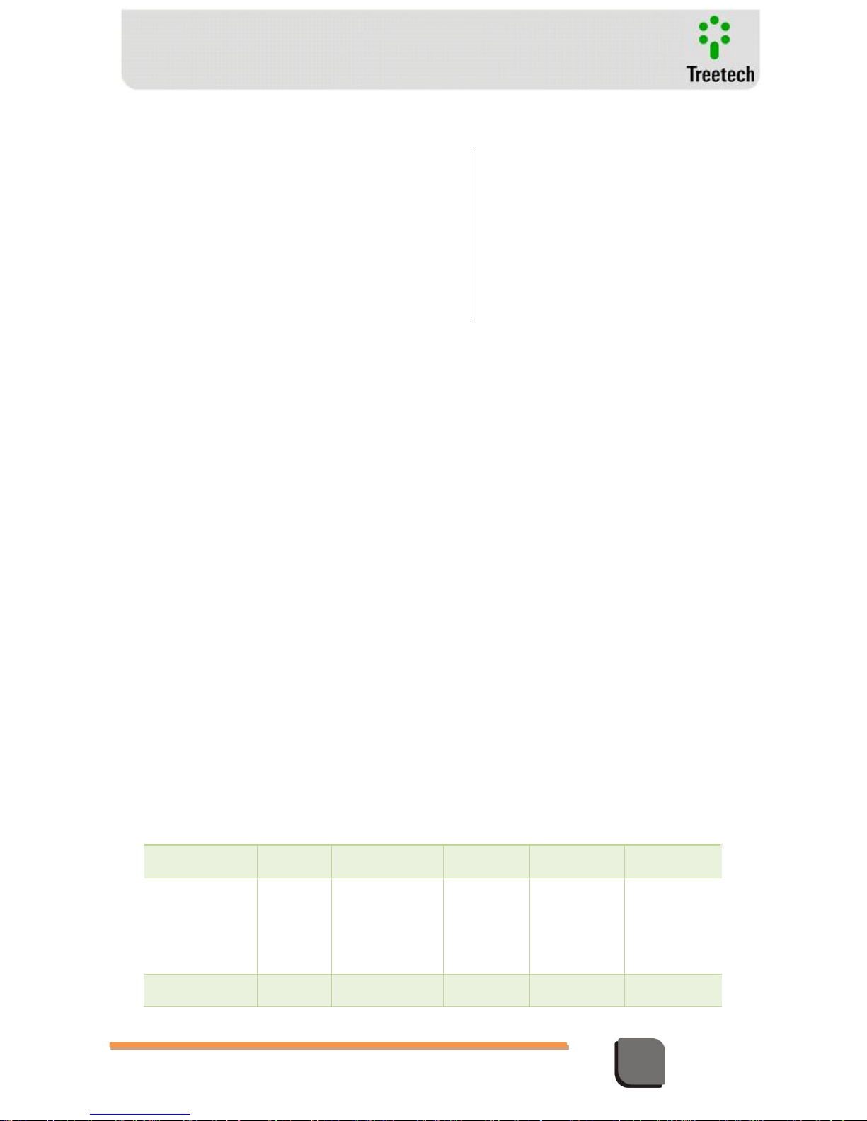
Technical Manual – TM1/TM2 | MA-010| 2016-03-21 | Ver.: 6.30 93
Temperature Monitor
Amplitude:
Duration:
0,075mm from 10 to 58 Hz
1G from 58 to 150 Hz
8 min/axis
Vibration resistance: (IEC 60255-21-1):
Application mode:
Frequency
Amplitude:
Duration:
3 axis (X, Y e Z), sinusoidal
10 to 150 Hz
2G
160 min/axis
Short duration overload (IEEE C57.109-1993 and NBR
8145/83):
AC current measurement inputs
8.4 Attachment D
Compatibility between versions
This is an informative about the compatibility between the available versions of the Treetech Temperature
Monitor, complying with the device’s three generations: MT, Three Keys TM an Four Keys TM.
Frequent questions:
1. Is it possible applying TM1 and TM2 with diferente versions?
Yes, but with a few restrictions. According to the table below. Nevetheless, it is always recommended to
use equipments with the same firmware version, as they are updated and tested together by Treetechs’
Team.
2. Is it possible applying MT1 with TM2?
Yes, observing the compatibility described in table below.
3. Is it possible applying TM1 with MT2?
Yes, observing the compatibility described in table below.
Table 15 – Compatibility between firmwares
Equipamento
Compatível com:
Type
Model
Last version
Typo
Model
Version
MT1
All
2.3
MT2
TM2
TM2
All
3 Keys
4 Keys
2.3
2.02 a 3.14
3.05 a 3.10
MT2
All
2.3
MT1
All
2.3
Page 94
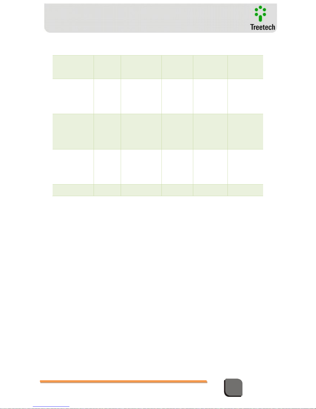
Technical Manual – TM1/TM2 | MA-010| 2016-03-21 | Ver.: 6.30 94
Temperature Monitor
TM1
TM1
3 Keys
4 Keys
2.02 a 3.14
3.05 a 3.10
TM1
3 Keys
3.14
MT2
TM2
TM2
All
3 Keys
4 Keys
2.3
2.02 a 3.14
3.05 a 3.10
TM2
3 Keys
3.14
MT1
TM1
TM1
All
3 Keys
4 Keys
2.3
2.02 a 3.14
3.05 a 3.10
TM1
4 Keys
4.14
4.16
TM2
TM2
4 Keys
4 Keys
3.05 a 4.14
4.15 a 4.16
TM2
4 Keys
4.16
TM1
4 Keys
4.00 a 4.16
Notes:
The above table has established compatibilities in deveces without any optionals.
The 3 Keys TM1 monitors, which versions are 3.05 or higher operate with 4 Keys TM2 version 4.14 or lower
in compatibility. There is an operational restriction for analog output of TM2.
Conclusion:
Starting with version 4.15, the TM1 monitors are not compatible with previous versions than 4.15. The
reason are the updates and new functions incorporated to TM1/TM2 monitors.
If there are any doubts about this attachment, please, contact Treetech’s Technical Assistance.
Page 95

BRAZIL
Treetech Sistemas Digitais Ltda
Praça Claudino Alves, 141, Centro
CEP 12.940-000 - Atibaia/SP
+ 55 11 2410-1190
www.treetech.com.br
 Loading...