

Page 1
AP13 - Ultimate Party
13’
OC
Cantilever
Assembly and Operation Guide
Page 2
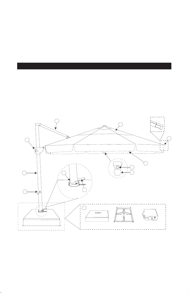
Thank you for your purchase of Treasure Garden’s AP13 Ultimate Party Cantilever
F
B
G
H
Base frameBase cover
Base Parts Boxed Separately
Add-on weights (4)
A
D
E
L
i
C
J
Spring Loaded
Rib End Cap (8)
K
Umbrella.
Please remove all contents from the package, inspect and review checklist.
CAUTION:To reduce personal injury and damage to your AP13, read and follow this
assembly and operation guide We recommend a two-person team for assembly and
disassembly. Save information for future reference.
AP13 CHECKLIST
A - Base Cover, Frame and Add-on Weights G - Canopy Support Beam
B - 360° Rotating Hub H - Canopy - Double Wind Vent
C - Base Pedal I - Valance
D - Crank Lift Handle J - Speakers
E - Main Frame Stand K - Center Light/Globe
F - Main Frame Grip and Media Center L - Spring Loaded Rib End Cap
REQUIRED FOR ASSEMBLY:
• 400 lbs. playground sand (not included).
NOTE: Some parts may be included in the styrofoam packaging.
DO NOT discard any packaging or box until assembly is complete.
Page 3
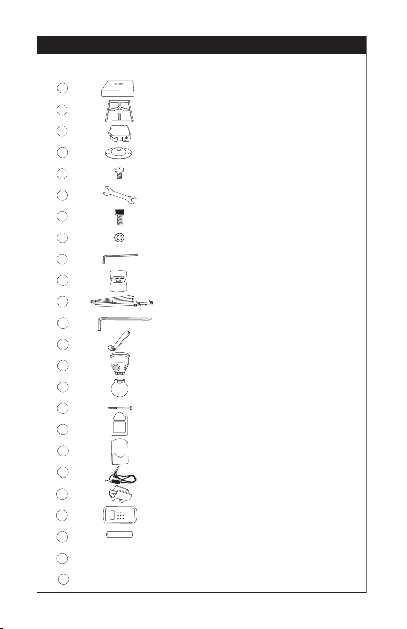
1 Base Cover 1
2 Steel Base Frame 1
3 Add-On Weight Containers 4
4 Feet 4
5 Screws 4
6
Wrench 1
7
Bolts 5
8 Washers 5
9
Medium Hexagon Wrench 1
10
Playground Sand (not included) 400 lbs.
11 AP13 Main Frame & Rotating Hub 1
12 Large Hexagon Wrench 1
13
Crank Lift Handle 1
14 Center Light/Speaker 1
15 Globe 1
16 Screws (long) 2
17 iPod/Remote Holder 1
18 iPod/Remote Holder Cover 1
19 Music Adapter Cord 1
20 Remote Holder for Umbrella Rib 1
21 Remote Control 1
22 AAA Batteries 5
23 Plug/Transformer/Cord 1
24 Protective Furniture Cover 1
AP13 PART LIST
Part Description Qty.
T
I
M
E
F
M
/
A
M
/
O
F
F
F
/
C
P
/
S
T
U
N
E
V
O
L
2
Page 4
Med. Hex. Wrench
S T E P 1 Base Assembly
TIME
FM/AM/OFF
iPod/MP3
ANT
F/C
P/S TUNE VOL
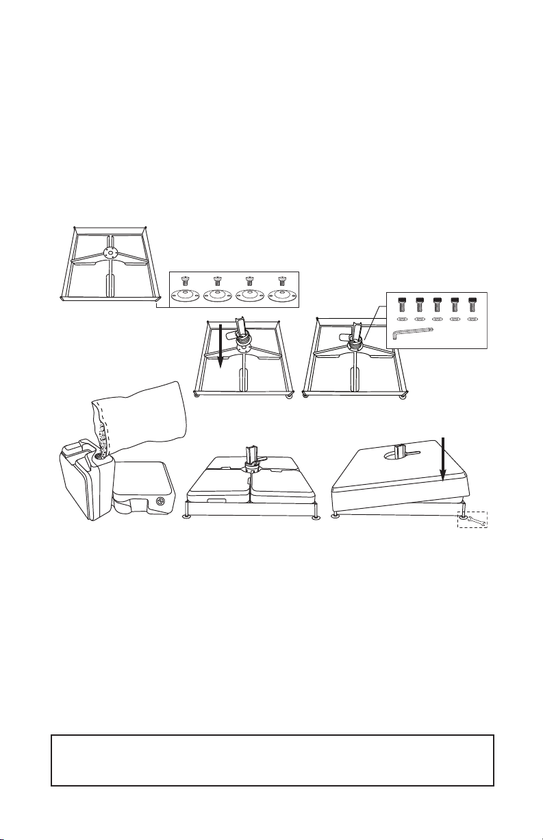
Select area to set base frame and place in desired location. NOTE: Moving the umbrella will
be difficult once fully assembled. Screw (4) feet onto bottom of base frame with supplied
(4) screws (Fig. 1). LEVELING: If needed, adjust base frame corners using supplied wrench
until base is level (Fig. 6). Now, place rotating hub onto base frame and secure with supplied
(5) bolts & (5) washers (Fig. 2). NOTE: ROTATING HUB IS IN SEPARATE BOX INSIDE
UMBRELLA CARTON. Remove caps from each add-on weight container and fill with dry
playground sand (Fig. 3). The AP13 base containers hold up to 400 lbs. of sand. IMPORTANT:
When filling the containers, it is necessary to wet down the sand after partial filling. After wet
down, fill each add-on weight with remaining sand. Place each add-on weight container into
base frame sections (Fig. 4). Carefully place base cover onto base frame (Fig. 5).
(Fig. 1)
(Fig. 3)
(Fig. 2)
(Fig. 4)
(Fig. 5)
IMPORTANT:Prior to assembly it is important to decide on the location of the AP13
umbrella. The umbrella measures approximately 10 1/3 ft. in height and 14 1/2 ft. in
width.
• Allow ample height to avoid damage to your umbrella during assembly and usage.
• Choose a location that is level and sturdy.
• Avoid any sloping or soft ground.
• Consider a location that will maximize the umbrella’s rotating swivel function. Placing
the AP13 between two entertaining areas is ideal.
• Access to electrical outlet within cord length will be required for use of umbrella lights.
CAUTION: Fully assembled, the AP13 umbrella weighs over 500 lbs. Moving the umbrella fully
assembled will increase the risk of damage to your umbrella and/or can cause serious injury. We
recommend a two-person team for assembly and disassembly.
(Fig. 6)
Page 5
Large
Hexagon Wrench
S T E P 2 Umbrella Assembly
Two-persons recommended for team lift and to complete assembly.
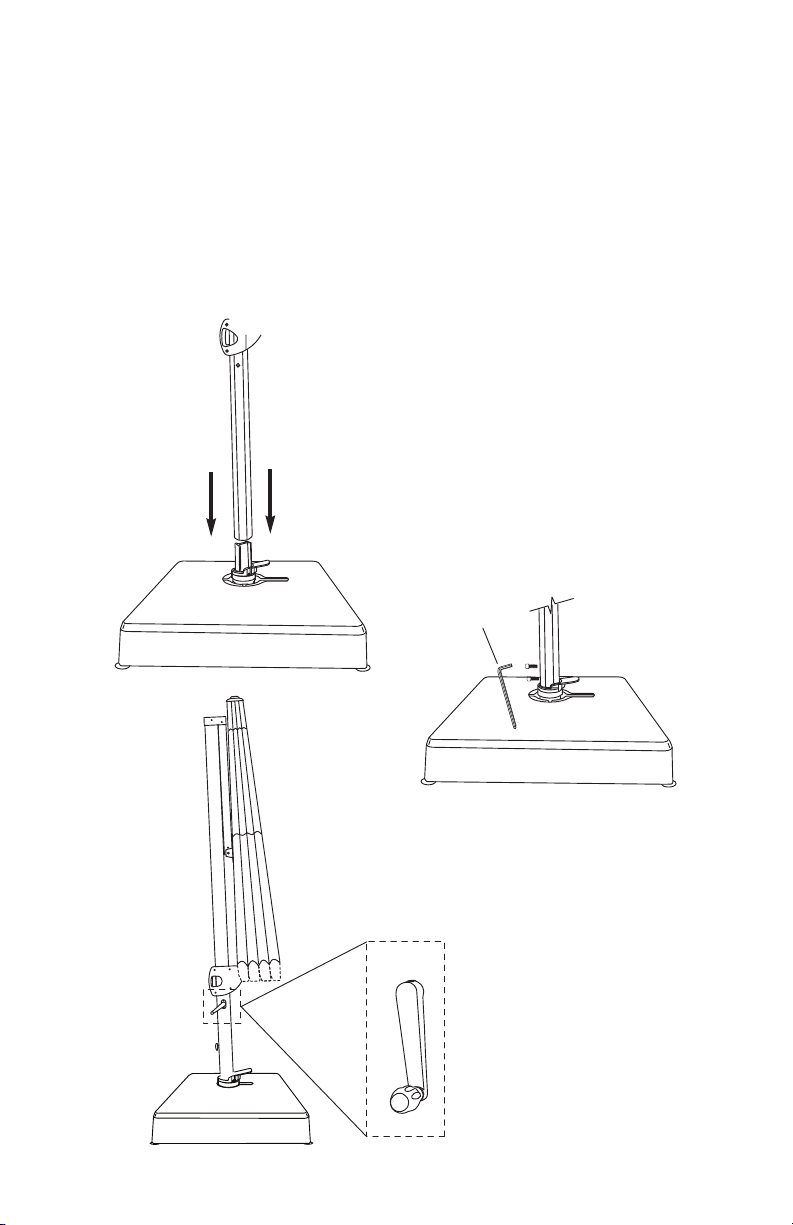
With base cover in place, insert the main frame onto the rotating hub (Fig. 7) {align with foot
pedal}. In upright position, insert (2) bolts and (2) washers and tighten using large hexagon
wrench provided (Fig. 8). Install the crank lift handle onto the mid-area of the main frame
(Fig. 9).
REMOVE ALL PLASTIC PACKAGING MATERIAL FROM ALL PARTS PRIOR TO
OPENING UMBRELLA. CHECK UNDER CANOPY FOR PACKAGING AROUND RIBS.
(Fig. 7)
(Fig. 8)
(Fig. 9)
411
Page 6
S T E P 3 Center Speaker/Light Assembly
TIME
FM/AM/OFF
iPod/MP3
A
NT
F/C
P/S TUNE VOL
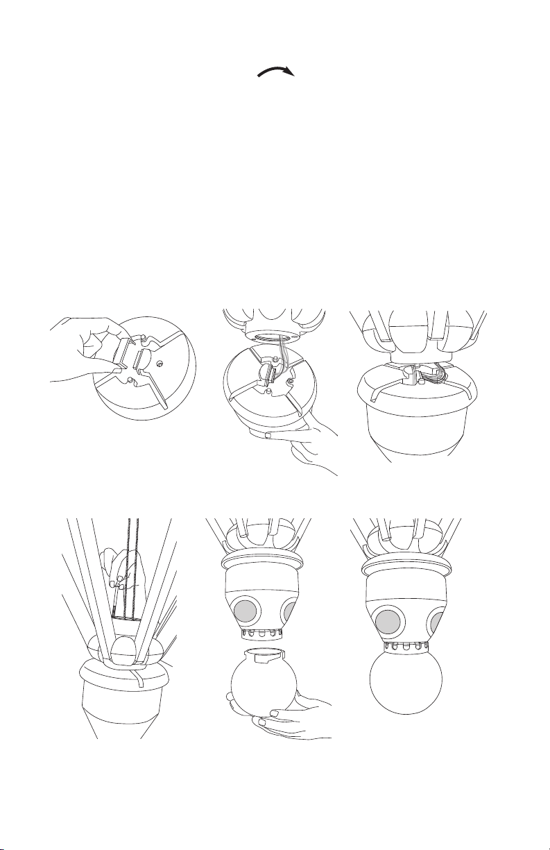
Slowly turn the crank lift handle clockwise to slightly open the umbrella to allow
yourself enough room to install center speaker/light.
loosen up the ribs by shaking gently to help with opening umbrella.
Remove protective cap off connector on center speaker/light (Fig. 10). Attach center
speaker/light connector to plug hanging from lower hub (Fig. 11). NOTE: Make sure holes
line up on connector and plug (Fig. 12).
Attach center speaker/light to lower hub by lining up screw holes. While holding center
speaker/light, tighten with 2 long screws with phillips screwdriver, into predrilled holes
located on top of the lower hub (Fig. 13).
Line up grooves on globe with speaker (Fig. 14). Turn clockwise to lock into place (Fig. 15).
(Fig. 10)
NOTE:
It is possible you may need to
DO NOT FORCE OPEN!
(Fig. 13)
(Fig. 11)
(Fig. 14)
(Fig. 12)
(Fig. 15)
Page 7
S T E P 4 Operation
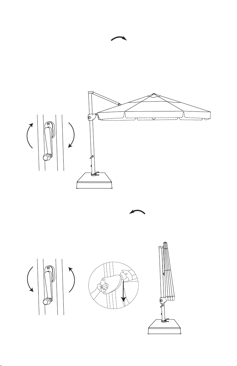
To Open Canopy:
Slowly turn the crank lift handle clockwise (Fig. 16) with one hand and with the
other hand, depress main frame grip to disengage and slide the main frame grip up until
the canopy is fully open (Fig. 17). CAUTION: Stop turning the crank handle as soon as the
umbrella cover is completely open and the arm on the umbrella pole has reached its
maximum height. WARNING: Do not continue to crank once umbrella canopy is
completely open, it may damage umbrella.
(Fig. 16)
(Fig. 17)
To Close Canopy:
Slowly turn the crank lift handle counter-clockwise (Fig. 18) with one hand and
with the other hand, depress main frame grip to disengage (Fig. 19) and slide the main
frame grip down until the canopy is fully closed (Fig. 20).
(Fig. 18)
(Fig. 19)
(Fig. 20)
6
Page 8
AP13 Features
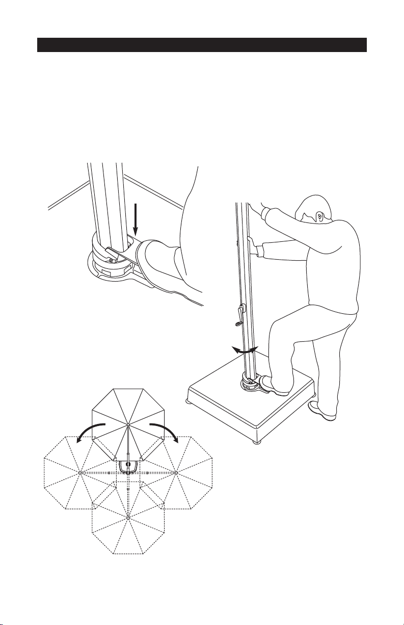
To OPERATE the 360° Rotating Hub Swivel:
Place your foot on the foot pedal of the rotating hub and step-on the base pedal
to release rotating lock (Fig. 21). Place both hands on the main frame (Fig. 22) and swivel
the umbrella frame in either direction until desired position is reached (Fig. 23). Step off the
foot pedal to engage rotating lock and lock position (you will hear the pedal click, as it
reaches the next available lock position).
(Fig. 21)
(Fig. 23 )
(Fig. 22)
Page 9
AP13 Features
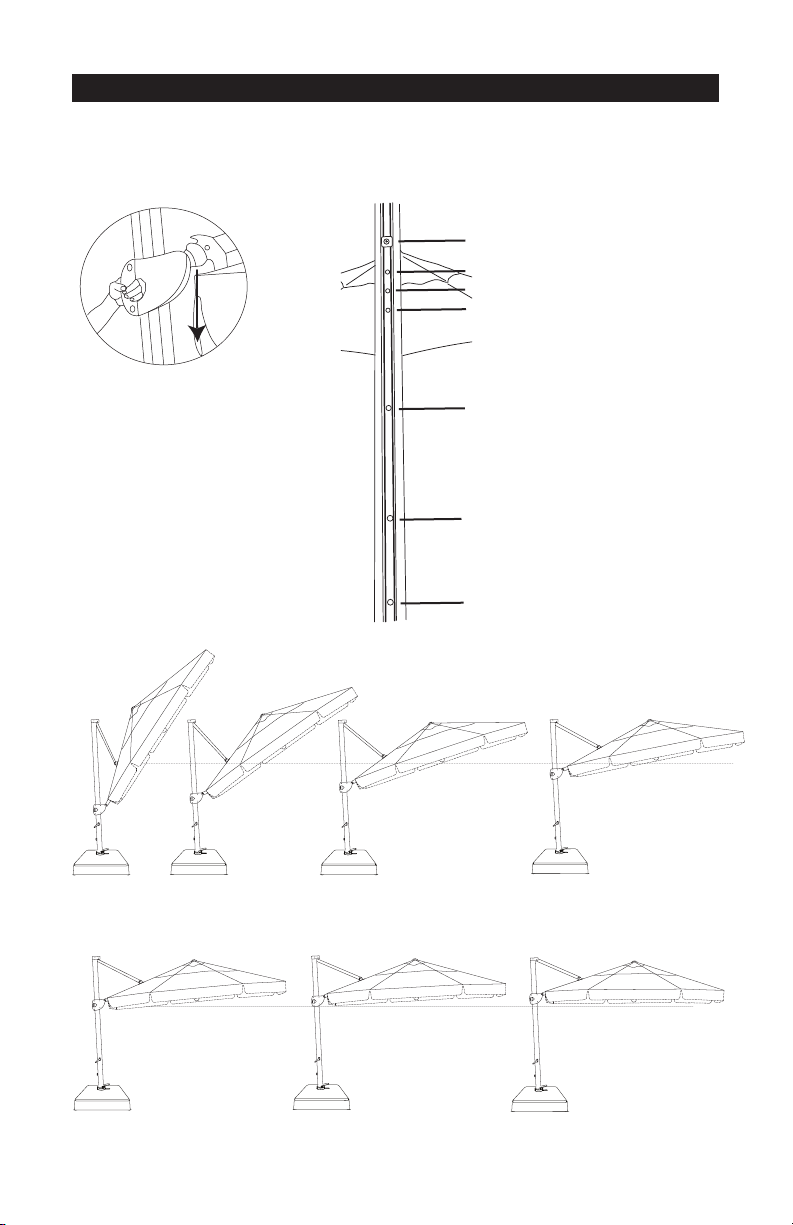
To TILT:
To tilt umbrella, squeeze the main frame grip handle (Fig. 24) and slide handle to desired tilt
position (Fig. 25). Release main frame grip handle to lock into tilt position.
Horizontal Position Hole
Tilt Position #1 Hole
Tilt Position #2 Hole
Tilt Position #3 Hole
(Fig. 24)
Tilt Positions (Fig. 25)
Tilt Position
#6/Closed
Tilt Position #5
Tilt Position #4
Tilt Position #4 Hole
Tilt Position #5 Hole
Tilt Position #6/Closed
Tilt Position #3
Tilt Position #1Tilt Position #2
Horizontal Position
87
Page 10
AP13 Features
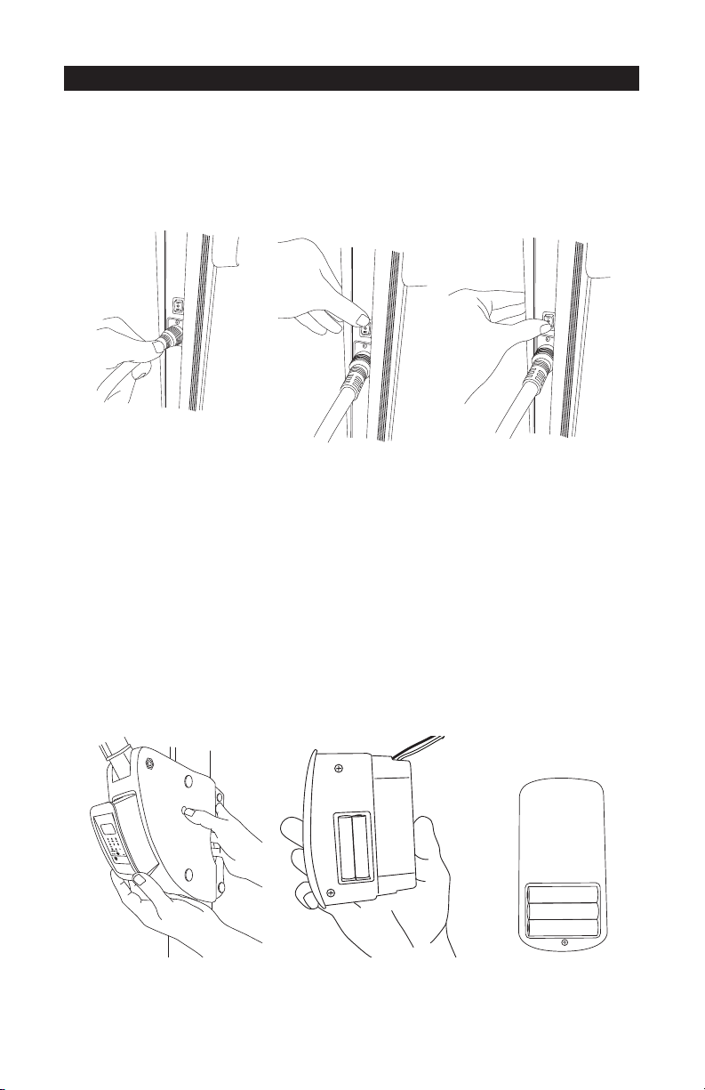
Plug In Lights:
Insert plug into main frame (Fig. 26). Plug other end into wall. To turn on center light,
press switch up (Fig. 27). To turn on center light and starlights, press switch down (Fig. 28).
To turn off all lights, return switch to center position.
store away plug & transformer when not in use.
NOTE:
Keep AP13 unplugged and
(Fig. 26)
(Fig. 27)
(Fig. 28)
Media Center:
Batteries for Media Center:
Insert (2) AAA batteries into media center by pressing the release button located on the
side of the main frame grip (Fig. 29). Remove battery cover and insert (2) AAA batteries
(Fig. 30). Snap side battery cover back onto media center and insert media center back
into main frame grip. Media Center is now ready for use.
Batteries for Remote Control:
Insert (3) AAA batteries into back of remote control (Fig. 31). Snap back cover back onto
remote control. Remote Control is now ready for use.
(Fig. 29)
(Fig. 30)
Media Center
(Fig. 31)
Remote (Back Side)
9
Page 11
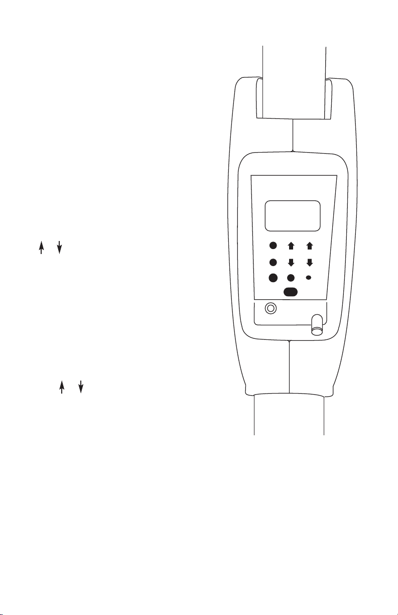
To use Media Center:
TIME
FM/AM/OFF
iPod/MP3
A
NT
F/C
P/S TUNE VOL
(Fig. 32)
To turn media center on, press the FM/AM/OFF
button on the media center or remote control.
Radio will turn on to FM radio. The FM radio
station, radio volume and current temperature
will appear in the display. Press FM/AM/OFF
button again and radio will switch to AM radio.
Press a third time, media center will turn off with
the clock and current temperature in the display.
Display screen stays on for approximately 30
seconds for any of the 3 settings until going into
sleep mode.
To program a radio station:
(Fig. 32)
The media center programs up to 9 stations. To
program, turn on radio to desired band. Press
or tune button to desired station. Press P/S
button for 2 seconds until desired program
number appears and is flashing. Press P/S again
for 2 seconds and program number will stop
flashing. Station has now been programmed.
Repeat steps for additional programmed
stations.
NOTE:
Batteries must be installed into
media center for memory programming.
To adjust volume:
(Fig. 32)
Press or volume button on media center or
remote control.
(Fig. 32)
105
Page 12
Large
Hexagon Wrench
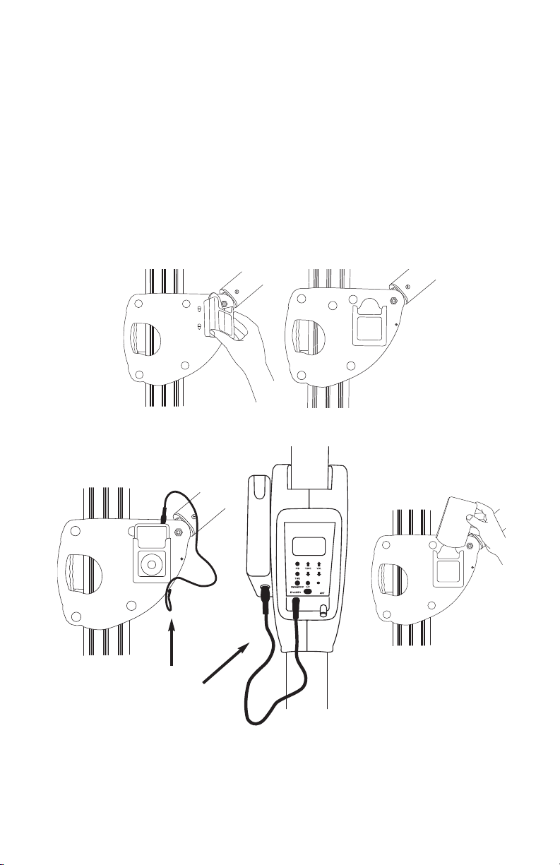
To use iPod or MP3:
Install iPod/Remote Holder onto side of main frame grip. Line up holes on back side of
holder to main frame grip and slide into place (Fig. 33). Holder can hold remote control or
your iPod/MP3 player.
Plug one end of the music adapter cord to the iPod or MP3 and plug the other end into
the media center (Fig. 34). Select music to play on your iPod/MP3. Make sure the volume
is all the way up on your iPod/MP3 and use the volume controls on the media center or
remote control to adjust volume.
Slide cover over holder to protect accessory (Fig. 35).
(Fig. 33)
(Fig. 34)
(Fig. 35)
Page 13
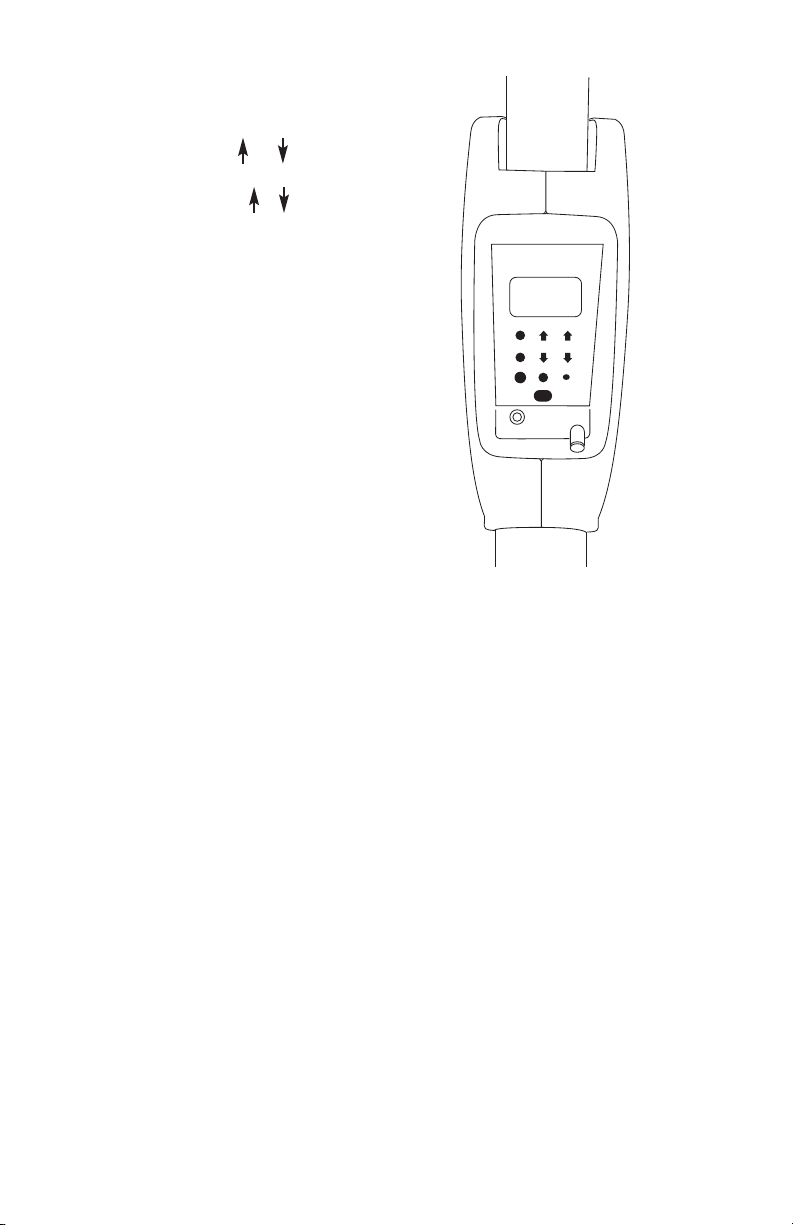
To set the time:
TIME
FM/AM/OFF
iPod/MP3
ANT
F/C
P/S TUNE VOL
(Fig. 36)
With the media center on, press TIME button
on media center or remote control until hour
indicator flashes. Press or volume
button to set hour. Press TIME button to
switch to minutes. Press or volume
button to set minute. Press TIME to save.
To change temperature options:
(Fig. 36)
Press F/C button to change between
fahrenheit and celsius on media center or
remote control.
P R O T E C T I V E C O V E R
1. Screw rods together and insert into slit of the cover.
2. Unzip cover.
3. Using the rod as a guide, slide cover over your umbrella.
4. Pull on string to zip down your cover and tie.
(Fig. 36)
123
Page 14

S A F E T Y P R E C A U T I O N S :
1 Base Cover 1
2 Steel Base Frame 1
3 Add-On Weight Containers 4
4 Feet 4
5 Screws 4
6
Wrench 1
7
Bolts 5
8 Washers 5
9
Medium Hexagon Wrench 1
10
Playground Sand (not included) 400 lbs.
11 AP13 Main Frame & Rotating Hub 1
12 Large Hexagon Wrench 1
13
Crank Lift Handle 1
14 Center Light/Speaker 1
15 Globe 1
16 Screws (long) 2
17 iPod/Remote Holder 1
18 iPod/Remote Holder Cover 1
19 Music Adapter Cord 1
20 Remote Holder for Umbrella Rib 1
21 Remote Control 1
22 AAA Batteries 5
23 Plug/Transformer/Cord 1
24 Protective Furniture Cover 1
AP13 PART LIST
Part Description Qty.
T
I
M
E
F
M
/
A
M
/
O
F
F
F
/
C
P
/
S
T
U
N
E
V
O
L
• Close the umbrella in windy conditions or when a storm approaches.
Never allow the umbrella to flap in the wind; this could damage the canopy.
• Do not leave open umbrella unattended. If damage occurs, this is not covered
by the warranty.
• When adjusting the umbrella, make sure that no person(s) or item(s) are close to the
umbrella. This is important to prevent injury or material damage.
C A R E A N D M A I N T E N A N C E :
• When not in use, close and cover umbrella with a protective cover.
• If necessary, clean the fabric with lukewarm water, mild detergent, and a sponge.
• Allow a wet canopy to dry slightly opened, but do not leave unattended.
• Wipe sliding marks on the aluminum poles with a damp cloth.
Winter Storage:
• Store in a dry place.
• Any visible defects must be repaired by a professional.
After the Winter:
• Areas subject to turning and sliding can be treated with a non-staining lubricant spray
(silicone-based).
• Check the condition and function of the umbrella. Any defects must be repaired by a
professional.
CAUTION: Fully assembled, the AP13 umbrella weighs over 500 lbs.
Moving the umbrella fully assembled will increase the risk of damage to your umbrella
and/or can cause serious injury. We recommend a two-person team for assembly
and disassembly.
13
Page 15

WARRANTY:
Treasure Garden warrants this product
(in residential use) to be free from
defects in original materials and
workmanship for a period of 2 year from
the date of purchase. If a defect in the
original material or workmanship
appears during the warranty period;
Treasure Garden will (at its option) repair
or replace the product without charge.
Simply contact your original authorized
Treasure Garden dealer with a
description of the defect. The dealer will
verify the defect and work closely with
Treasure Garden to obtain the necessary
service. In many cases, simple problems
can be solved with a replacement part
that can be shipped directly to the dealer
for professional installation / repair.
In the event that warranted factory
service is required, Treasure Garden will
assume the responsibility of the return
freight charges on warranted product for
2 years.
Returned product that (upon receipt and
inspection) is deemed to be “not
covered” under our warranty, will be
shipped / billed at your expense.
This warranty gives you specific legal
rights, and you may have other rights
which vary from state to state.
RUST: Rust is a natural part of the
aging process of steel or iron based
materials, and is therefore NOT
considered a defect.
NOTE: Failure caused by unreasonable
or abusive use, or failure caused by
neglect of reasonable and necessary
care are not covered by this warranty.
Additionally, acts of nature (including but
not limited to wind, hurricanes,
tornadoes, and storms) are not covered
by this warranty.
141
Page 16

www.treasuregarden.com
©2013 Treasure Garden, Inc. - All Rights Reserved. Rev. 4/1
 Loading...