

TRC UNIVERSAL IRRIGATION REMOTE CONTROL, Commander Operation And Installation Manual
UNIVERSAL IRRIGATION REMOTE CONTROL
Operation and Installation Manual
COMMANDER

COMMANDER
UNIVERSAL IRRIGATION REMOTE CONTROL
FCC REGULATIONS
The user of this remote control device does not need an FCC license.
The Receiver has been tested and found to comply with the limits for a
Class A digital device, pursuant to Part 15 of the FCC Rules. The Transmitter has been tested and found to comply with Part 95 Subpart E. These
limits are designed to provide reasonable protection against harmful interference when the equipment is operated in a commercial environment.
Canadian Certification #32151021261
2 800-275-8558 www.remotecontroltech.com
Fault Indication Correction
Check if the Receiver number was inadvertently
changed. Reprogram the Transmitter codes to match
the Receiver codes. (Press "1", "REC #")
Check the Group Code and Receiver Code dipswitches
on the Receiver. Reprogram the Transmitter to match
the Receiver codes. (See page 13).
Use an ohmmeter to check that your connector's
wire assignment matches your controller's valve
assignment.
Install the RC Series Controller Isolation Relay
(Part #02002).
Check solenoid. Current drain is more than 3 amps
and is tripping the resetting fuse.
Ensure that the antennas are firmly attached to the
Receiver and Transmitter.
Ensure that the antenna is clear from obstructions. The
three feet immediately surrounding the antenna are the
most crucial and should be kept clear of obstructions,
power lines, or electrical conduits, electric motors etc.
Keep the antenna as high as possible on the controller
and avoid situations where the antenna can be
shadowed by buildings or large metal structures.
Ensure that the Receiver's antenna is as far away from
electric motors, V.F.D.'s and overhead powerlines as
this type of equipment causes interference.
Receiver fails to
respond, but the
power light is on.
Receiver’s “Valve
On” indicator lights
during initial test,
but no valve or wrong
valve comes on.
Rain Bird’s RC series
controller advances
to the first station with
remote operation.
Receiver turns off when
one station is activated.
Short Range
27
800-275-8558 www.remotecontroltech.com

INTRODUCTION
Congratulations! You have just purchased the most advanced
irrigation remote control available - the TRC Commander.
We welcome you to the growing family of thousands of satisfied
Remote Control Technology product users who appreciate the importance of high standards, product quality and timely service.
The new TRC Commander is RCT's 6th generation of remote control products introduced since 1982. All of our remote control products do not require site surveys, base stations or FCC licensing.
All Remote Control Technology, Inc. products carry a "THREE YEAR
WARRANTY".
For three years from the date of purchase, Remote Control Technology, Inc. will repair or replace any of its products or parts to be found
defective as to workmanship or materials. This warranty does not
extend to damage to a Remote Control Technology, Inc. product resulting from misuse, neglect or abuse, improper installation or accident.
This warranty extends only to an original user of Remote Control
Technology, Inc. product(s). In no event shall Remote Control Technology, Inc. be liable for incidental or consequential damages. All
implied warranties are limited in duration to three years following date
of purchase. These exclusions or limitations apply only in those
states where permitted by law.
WARRANTY
3
800-275-8558 www.remotecontroltech.com

Models and Description
Transmitter
TRC Commander Transmitter is the hand-held part of your
remote system. Any 24VAC solenoid valve sprinkler system
equipped with a TRC Universal Receiver or TRC Permanent
Receiver Card can be operated with this Transmitter. The Transmitter operates on one 9-volt alkaline replacable battery.
Note: The battery must be alkaline or the transmitter will
not operate.
Receivers
Universal 32 Station DCI Receiver is compatable with all
24VAC solenoid valve sprinkler systems and is capable of operating 32 stations per controller. This portable Receiver connects easily with a permanent connector hard wired to the terminal strip and a custom housing mounted on the controller for
quick plug in.
Permanent Receiver Cards install easily and permanently into
the controller. Installing Permanent Receiver Cards allows all
zones of the controller to be operated. Each Card comes with
internal and external antennas w/mounting hardware. Maximum
range is achieved by installing the external antenna to the controller cabinet.
4 800-275-8558 www.remotecontroltech.com
DCI-2
To disconnect the DCI-2 Cable:
NOTE: TRC COMMANDER RECEIVER MUST BE CON-
NECTED TO 37-PIN CLAMSHELL BEFORE DISCONNECT-
ING DCI-2 CABLE FROM CONTROLLER. To disconnect the
DCI-2 cable from the controller, twist the circular plug in a counter-
clockwise motion and remove from the DCI-1 cable. Remove
the 37-pin clamshell from TRC Commander Receiver and store
the cable in carrying case when not in use. Extreme care
should be taken with the DCI-2 cable to safeguard the in-
tegrity of its circuitry.
DCI-1
25
800-275-8558 www.remotecontroltech.com

Special Features
• Connects to any 24VAC sprinkler system
• Silent Running
-Turn off all of the zones from 1 - 7 days
• Adjustable Time Duration
-2 Minutes to 2 Hours (default 20 minutes)
• Multiple Receiver operation from a single Transmitter
- Field programmable dipswitches offer
199 unique Receiver numbers
• Programmable security codes
-9999 different security group codes
• Audible low power indicator
-Field replaceable 9 volt battery
• Master Valve disable key
-Pump Start/Master Valve
Permanent Receiver Cards are available for the following
controllers:
Rain Bird ESP MC® (contact factory for SAT upgrades)
Rain Bird ESP LX®
Irritrol Dial & MC®
Superior Sterling®
HIT Logic 2 & 3®
Griswold IDC®
5
800-275-8558 www.remotecontroltech.com
Alkaline
Transmitter uses one replacable 9V Alkaline battery.
Getting To Know The Transmitter
The TRC Commander Transmitter sends a proprietary FM signal to the Commander Receiver(s) turning on or off selected
valves. With each valve activation or deactivation, the Pump
Start/Master Valve station, when used, is automatically turned
on or off unless "MV Off" has been pressed.
The Transmitter is designed for minimal power consumption
to extend the life of the battery. The Transmitter power is
normally off. Once any key has been pressed, power is automatically turned on for about ten seconds to allow your command sequence to be completed before the Transmitter automatically turns the power off and erases the command sequence from memory.
6 800-275-8558 www.remotecontroltech.com
Step 1: Use (figure 4 from the pamphlet with your PCC) as a
pattern to locate the mounting holes to be drilled
through the controller.
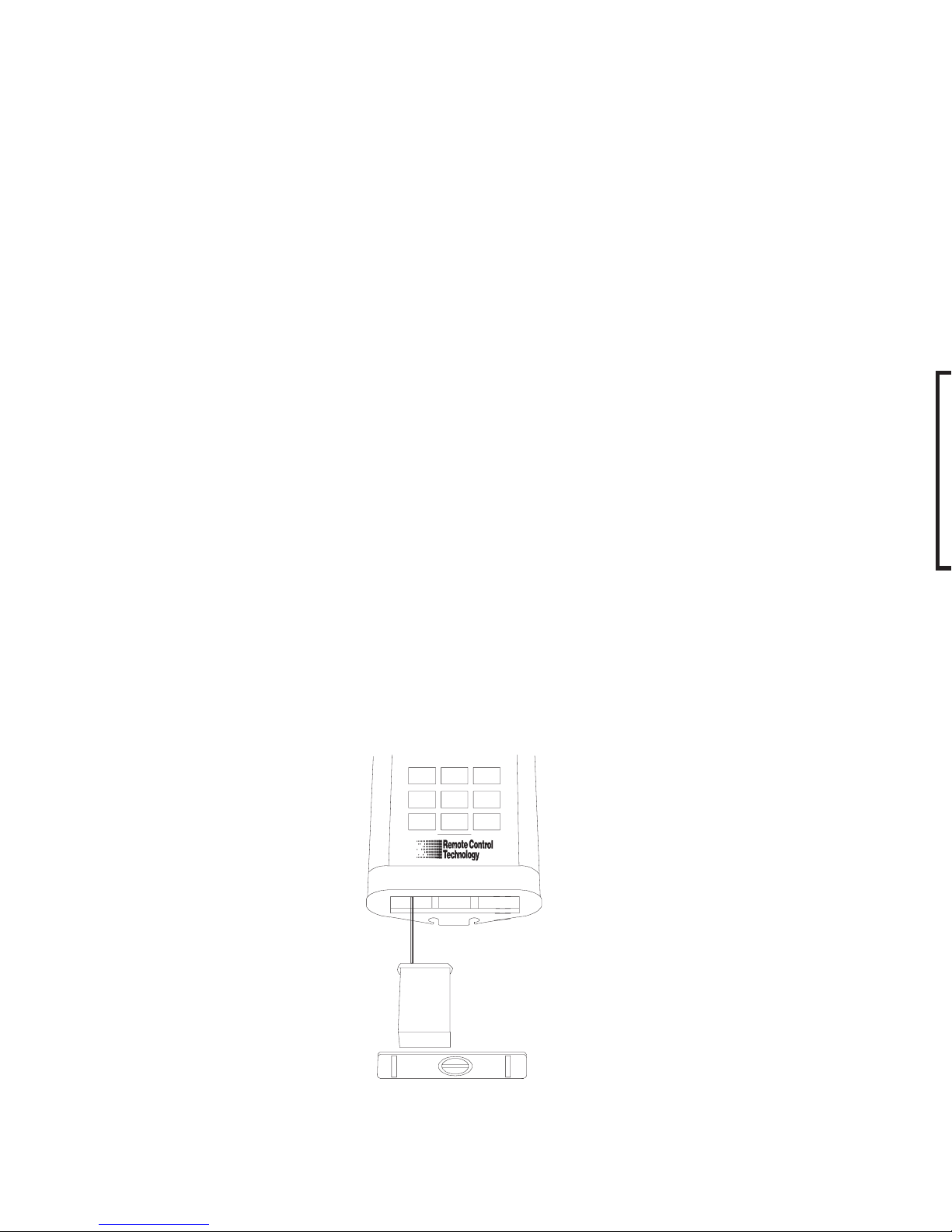
Step 2: Peel off sticker and attach gasket on back of housing.
Step 3: Peel off sticker and attach gasket to inside door. Make
sure gasket is snug against side walls for maximum
seal.
Step 4: Locate 1" socket head cap screw and insert thoughhole
on door. Slip on retainer ring approximately 3/16" from
threaded end of cap screw.
Step 5: Mount housing to controller using two 6-32 x 3/4"
machine screws, two flat washers, two lock washers,
and two hex nuts.
Step 6: Attach D-Sub connector to the inside housing with two
4-40 x 9/16" machine screws. Do so by first inserting
the end of wires through the 1/2" hole in the sprinkler
controller. Attach connector with the longer row of pins
to the left. Hold connector to highest position while
tightening. Follow wiring code for connecting cables.
Instructions also provided with PCC.
Warning
Do not have the Receiver plugged into connector cable
while installing connector or damage may occur.
Do not have 24VAC transformer plugged into Receiver
with the connector when the connector has 24VAC
from the controller!
Wiring Your PCC
23
800-275-8558 www.remotecontroltech.com
Step 1: Use (figure 4 from the pamphlet with your PCC) as a
pattern to locate the mounting holes to be drilled
through the controller.
Step 2: Peel off sticker and attach gasket on back of housing.
Step 3: Peel off sticker and attach gasket to inside door. Make
sure gasket is snug against side walls for maximum
seal.
Step 4: Locate 1" socket head cap screw and insert thoughhole
on door. Slip on retainer ring approximately 3/16" from
threaded end of cap screw.
Step 5: Mount housing to controller using two 6-32 x 3/4"
machine screws, two flat washers, two lock washers,
and two hex nuts.
Step 6: Attach D-Sub connector to the inside housing with two
4-40 x 9/16" machine screws. Do so by first inserting
the end of wires through the 1/2" hole in the sprinkler
controller. Attach connector with the longer row of pins
to the left. Hold connector to highest position while
tightening. Follow wiring code for connecting cables.
12
3
4
56
78
9
AUTO
UP
TIME
AUTO
BACK
0
COMMANDER
REC
#
MV
OFF
VALVE
OFF
VALVE
ON
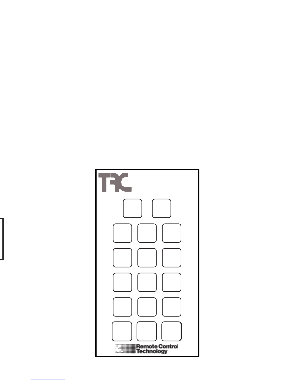
The Transmitter Key Pad
The Commander Transmitter keypad has an audible beep to
clearly indicate when a key is pressed. The Transmitter will
beep once when a Number Key or the Receiver Number Key is
pressed. The Transmitter will beep twice, with about two seconds between beeps, after a transmit key is pressed for ("VALVE
ON", "VALVE OFF", "AUTO UP", "AUTO BACK", "M-V OFF"
or "TIME"). The first beep indicates that the transmission is
starting, and the second beep indicates that transmission has
been completed.
7 800-275-8558 www.remotecontroltech.com

VALVE
ON
3
VALVE
ON
VALVE
OFF
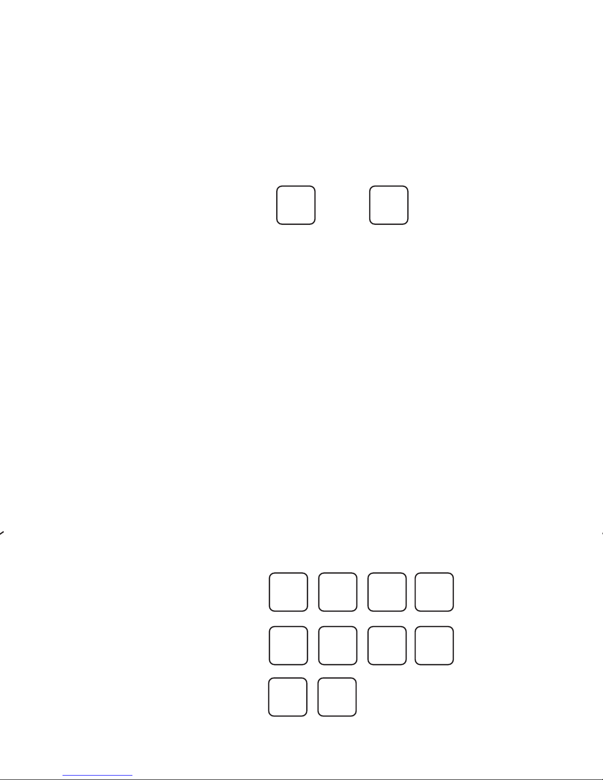
To turn off valve 3:
To turn on valve 3:
Turns zone 3 back on:
Transmitter Operating Instructions
Error Tone
You will hear a squak error tone if an incorrect series of keys have
been pressed. When the error tone is heard, wait 10 seconds and
simply restart the series of commands.
Low Battery Tone
A rapid sequence of beeps after the transmission beep indicates low
battery power. Replace with a new alkeline 9V battery.
Valve On/Valve Off
To turn a valve on press the desired zone number then press the
"Valve On" key. Pressing "Valve Off" will turn off the last zone activated.
When "Valve Off" is pressed by itself the current zone will turn off. To
turn that zone back on just press "Valve On". The Transmitter remembers which valve you were testing.
Pressing "0", "Valve Off" will turn off all zones.
Example:
8 800-275-8558 www.remotecontroltech.com
Installation Instructions:
Step 1: Remove power from controller first!
Step 2: Remove the controller's lower faceplate by removing the
screws on each side.
Step 3: Clean lower right, inner side panel (inside controller, behind
front panel). Install the Receiver Card by pressing it onto the
spot you just cleaned. The Card comes with the double-
sided tape on the back (see picture below).
Step 4: Connect the interface cable (with white molex connector)
from the Card into the six pin interface socket on the
controller labeled "RF INTERFACE" (see picture below).
Step 5: Connect the antenna to the BNC fitting located on the
Receiver Card to have your antenna located inside the
controller or connect the threaded external mount antenna
with coax cable for max. range. The holes for the "Side-
Mount" antenna mount are pre-drilled on the right-hand side
of the controller.
Step 6: Re-install the controller faceplate and re-apply power.
Receiver Cards for the HIT Logic 2
and Hit Logic 3 Controller
Receiver Card
Molex connector
Interface Cable
21
800-275-8558 www.remotecontroltech.com
Multiple Zones
Press the "9" key before a two digit zone number to turn on a
multipe zone. Example: "903", "Valve On" will turn zone 3 on.
You may have up to six multiple zones on at a time and a single
zone plus a master valve. Multiple zones cannot be changed
by the "Auto Up" or the "Auto Back" functions, but they can have
an independent time duration.
A station registered for multiple mode operation will not be turned off
automatically when other stations on the same Receiver are turned
on. Also, the single mode station will not be automatically turned off
when multiple mode stations are turned on. If you try to turn on a
seventh multiple mode valve, the first multiple mode valve turned on
will be automatically turned off.
WARNING: Make sure your controller has adequate power to
operate the number of multiple stations you intend to have on
at one time. Otherwise, you may overload the circuit breaker
at your controller.
2
2
VALVE
ON
VALVE
ON
09
39
To operate press:
AUTO
BACK
OR
AUTO
UP
Auto Up/Auto Back
These functions allow forward and backward advancement
through each station. This will turn on the next
sequential station number.
To turn all zones off
:
Adding zone 2:
Adding zone 32:
0
VALVE
OFF
9
800-275-8558 www.remotecontroltech.com
 Loading...