

Page 1

World HQ
US Office
Internet
Telephone
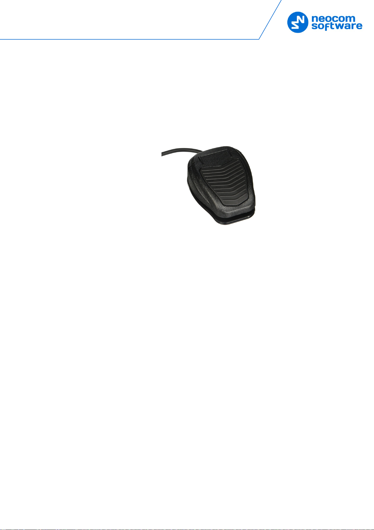
TRBOnet
Swift Footswitch P001
User Guide
Neocom Softwar e
8th Line 29, Vasilyev s ky Isl a nd
St. Petersburg, 19 900 4, Rus sia
Neocom Softwar e
15200 Jog Road, Suite 202
Delray Beac h, FL 33446, USA
Email: info@trbonet.com
WWW.TRBONET.COM
Last revised on November 20, 2019
EMEA: +44 203 608 0598
Americas: +1 872 222 8726
APAC: +61 28 6078325
Page 2
Introduction
1 Introduction
The TRBOnet Swift Footswitch P001 (hereinafter "footswitch") allows the
dispatcher to push and release the PTT button while their hands are free. There are
two design versions of the footswitch: with RS-232 and RJ-45 connectors,
respectively. To connect a footswitch to the PC via a USB port, you'll have to use a
footswitch with RJ-45 connector and an additional TRBOnet Swift Adapter M002
(hereinafter, "M002 adapter").
1.1 Technical features
• Plug connection: RS-232 or RJ-45
• Connector cable: 1,8 m
• Dimensions: 78/103/39 mm
• Weight: 250 g
• Material: plastic
• Color: black
1
Page 3

2 Configuration in TRBOnet Enterprise
2.1 Connecting via COM-port
This section describes how to connect the footswitch to the PC via a COM-port and
configure required parameters in TRBOnet Dispatch Console.
• Connect the footswitch to the PC via a COM-port.
• Run TRBOnet Dispatch Console.
• On the Tools menu, click Options.
• In the Options dialog box, select the Hardware tab.
• In the External Devices section, click the Add link and from the drop-down
menu select TRBOnet Footswitch.
The TRBOnet Footswitch dialog box appears on top of the Options dialog
box.
2 TRBOnet Swift Footswitch — User Guide
Page 4

Configuration in TRBOnet Enterprise
Name
Enter the name of the footswitch device.
Device
From the drop-down list, select COM3.
The Footswitch PTT button appears in the table below.
Press the footswitch button and see if the indicator box becomes green.
Release the footswitch button and see if the indicator box returns to red.
Note: If pressing the footswitch button doesn't change the
indicator's color to green, try toggling the polarity inversion
switch.
Click OK.
As a result, the footswitch device will appear in the list of External Devices.
3
Page 5

2.2 Connecting via USB-port using the M002 adapter
This section describes how to connect the footswitch to the PC via a USB-port and
configure required parameters in TRBOnet Dispatch Console.
• Connect the footswitch to a USB-port of the PC by using the M002 adapter.
• Run TRBOnet Dispatch Console.
• On the Tools menu, click Options.
• In the Options dialog box, select the Hardware tab.
4 TRBOnet Swift Footswitch — User Guide
Page 6

Configuration in TRBOnet Enterprise
• In the External Devices section, click the Add link and from the drop-down
menu select HID.
The HID dialog box appears on top of the Options dialog box.
Click the Add link.
One more dialog appears on top:
• Name
Enter the name of the button.
• Autodetect
Click this link and press the footswitch button. See if the other fields
(Mask, Press, and Release) get populated with the appropriate hex
values.
• Click OK.
As a result, the footswitch button will appear in the list of buttons in the
HID dialog box.
5
Page 7

Press the footswitch button and see if the indicator box becomes
green. Release the footswitch button and see if the indicator box
returns to red.
Note: If pressing the footswitch button doesn't change the
indicator's color to green, try toggling the polarity
inversion switch.
2.3 Associating with PTT boxes
• In the Radio Interface pane, right-click on a PTT box for which you want to
use the TRBOnet footswitch, and on the context menu, select
Specify External PTT > [Device Name].
6 TRBOnet Swift Footswitch — User Guide
 Loading...