

Page 1
Radio-over-IP Gateway
TRBOnet Swift A200
User Manual
World HQ
Neocom Software
8th Line 29, Vasilyevsky Ostrov
St. Petersburg, 199004, Russia
US Office
Neocom Software
15200 Jog Road, Suite 202
Delray Beach, FL 33446, USA
Internet
Email: info@trbonet.com
WWW.TRBONET.COM
Telephone
EMEA: +44 203 608 0598
Americas: +1 872 222 8726
APAC: +61 28 6078325
Page 2

Legal Notices
Legal Notices
This document is for informational purposes only.
Neocom Software, Ltd offers no warranties, express or implied,
in this document.
Neocom and the Neocom logo, TRBOnet and the TRBOnet logo are either registered
trademarks or trademarks of Neocom Software, Ltd.
MOTOROLA, MOTO, MOTOROLA SOLUTIONS and the Stylized M logo are trademarks
or registered trademarks of Motorola Trademark Holdings, LLC.
Microsoft, Windows, SQL Server and the .NET logo are either registered trademarks or
trademarks of Microsoft Corporation in the United States and/or other jurisdictions.
Other product or company names mentioned herein may be trademarks of their
respective owners.
© 2015 by Neocom Software, Ltd. All rights reserved.
Last revised on 31 August 2016.
Page 3

Legal Notices
TRBOnet Agent A200 –User Manual i
Contents
1. Introduction ........................................................................................................................................................ 1
1.1. About This Document ........................................................................................................................ 1
1.2. About TRBOnet Swift ......................................................................................................................... 1
1.3. Contacts ................................................................................................................................................. 1
2. About Swift A200 .............................................................................................................................................. 2
2.1. Features ................................................................................................................................................. 2
2.2. Capabilities ........................................................................................................................................... 2
2.3. Delivery Kit ........................................................................................................................................... 3
2.4. Panels ..................................................................................................................................................... 4
2.5. Connectors ............................................................................................................................................ 5
2.6. LED Indication...................................................................................................................................... 6
2.7. Acronyms ............................................................................................................................................... 7
3. Setup and Connection ..................................................................................................................................... 8
3.1. Configuring Swift A200..................................................................................................................... 8
3.2. Installing the Option Board ........................................................................................................... 10
3.3. Configuring the Radio ..................................................................................................................... 12
3.4. Configuring the Option Board ...................................................................................................... 13
3.5. Connecting the Radio and the LAN............................................................................................. 14
3.6. Connecting Swift A200 to Power Supply .................................................................................. 14
3.6.1. DC Power Supply ................................................................................................................. 14
3.6.2. AC Power Supply ................................................................................................................. 15
3.6.3. Reading LED indications ................................................................................................... 15
4. Maintenance ..................................................................................................................................................... 16
4.1. Built-in Clock Battery Replacement ........................................................................................... 16
4.2. Memory Card Replacement ........................................................................................................... 17
Page 4
Introduction
1
TRBOnet Swift A200 — User Manual
1. Introduction
1.1. About This Document
The information in this document is intended for engineers responsible for building
MOTOTRBO radio networks and programming two-way radios for end users.
The document describes in detail how to connect, set up, and maintain the TRBOnet
Swift A200 hardware radio-over-IP gateway.
1.2. About TRBOnet Swift
TRBOnet Swift is a family of hardware products designed by Neocom Software
Solutions, Ltd for MOTOTRBO radio networks. The Swift family hardware is
presented by IP gateways, the ST001 option board, the DT500 data transfer module,
and the TR001 GSM tracker.
For more information on the TRBOnet Swift family products, refer to our website.
1.3. Contacts
Region Phone Email & Support
EMEA +44 203 608 0598
info@trbonet.com — general and
commercial inquiries
support@trbonet.com — technical
support
http://kb.trbonet.com — online
knowledge base
Americas +1 872 22 28 726
APAC +61 28 6078325
Page 5

About Swift A200
TRBOnet Swift A200 — User Manual 2
2. About Swift A200
TRBOnet Swift A200 is a hardware radio-over-IP gateway designed to interconnect
a MOTOTRBO two-way radio with a TRBOnet Server on an IP network.
2.1. Features
Small size and weight
Wireless and wired connection to MOTOTRBO
Work with multiple (up to 10) connected TRBOnet Servers
Interfaces:
• 7 I/O contacts for external hardware (SCADA, sensors, and other)
• NRF for the wireless connection to a MOTOTRBO radio
• USB for the wired connection to a MOTOTRBO radio
• LAN for the wired IP connection (Ethernet 10/100Base-T, 100 Mbit/s)
• Micro-USB port for programming
12V DC power supply
OLED display
Support for flash cards with capacities up to 32 Gb
Quick and easy connection and setup
Unattended operation that does not require regular maintenance
2.2. Capabilities
A gateway from a radio channel to an IP network
A MOTOTRBO radio connected to Swift A200 can transfer voice and data to all
connected TRBOnet Servers over IP. Swift A200 performs no encryption of the
transferred voice and data traffic.
Remote control
TRBOnet control room operators can control a connected MOTOTRBO radio
remotely by sending commands (power on/off, channel and zone selection) over
IP.
Self-check and alarm notification
Swift A200 performs continuous monitoring of all connections and physical
parameters (interior temperature, battery status). When an error is detected, the
device shows the corresponding information on the display and sends an alarm
notification to all connected TRBOnet Servers. The notification is displayed on
the screens of TRBOnet control room operators.
Page 6

About Swift A200
3
TRBOnet Swift A200 — User Manual
2.3. Delivery Kit
TRBOnet Swift A200 delivery kit includes accessories listed in Table 1.
Table 1: TRBOnet Swift A200 delivery kit
Item Description Quantity
TRBOnet Swift A200 The radio-over-IP gateway unit with a
factory-installed MicroSD card (4 Gb or
more) and a CR1220 battery.
1
TRBOnet Swift Transfer
ST001
The option board to be installed into a
MOTOTRBO radio.
1
Flex cable
The flex cable to connect the option
board to the main board of a
MOTOTRBO radio.
1
Micro-USB <> USB cable
The programming cable. 1
USB <> RADIO cable
The service cable to connect a
MOTOTRBO radio to Swift A200.
1
Micro-Fit connector
system
The Micro-Fit plug and the wire kit to
connect Swift A200 to 12V DC power
supply and external hardware.
1
Screw kit
1
Passport
1
Page 7

About Swift A200
TRBOnet Swift A200 — User Manual 4
2.4. Panels
FRONT PANEL
1. OLED display that shows connection status and self-check information.
2. Micro-B USB port used to connect the device to a computer.
REAR PANEL
1. DC power inlet.
2. Audio In and Audio Out for an analog two-way radio (not supported).
3. Micro-Fit 3mm pitch connector for 12VDC supply and/or external hardware.
4. LAN port.
5. USB port for a MOTOTRBO radio.
2 1 1
3 4 5
2
Page 8

About Swift A200
5
TRBOnet Swift A200 — User Manual
2.5. Connectors
Table 2: Connector pinouts
I/O connector
1. Power (GND)
2. Input (IN7)
3. Input/output (IO6)
4. Input/output (IO4)
5. Input/output (IO2)
6. UART input, 5V (RX)
7. Power (+12V)
8. Output (OUT7)
9. Input/output (IO5)
10. Input/output (IO3)
11. Input/output (IO1)
12. UART output, 5V (TX)
Page 9

About Swift A200
TRBOnet Swift A200 — User Manual 6
2.6. LED Indication
Table 3: LED icons
Icon State
Radio connection
Flashing icon: The radio is not connected or powered off.
Radio TX
Radio RX
IP connection
Digit (next to the icon): The number of connected TRBOnet
servers.
Flashing icon: The IP network is not connected.
Activity on the IP connection
Wireless connection to the radio
USB connection to the radio
Memory card
Flashing icon: The memory card is not detected.
Low battery charge
Flashing icon: Battery replacement is required.
Built-in clock not set
Flashing icon: The built-in clock is not set. The configuration
update or battery replacement is required.
Page 10
About Swift A200
7
TRBOnet Swift A200 — User Manual
2.7. Acronyms
Table 4: Acronyms
Acronym Description
AC Alternating current
CPS Customer Programming Software
DC Direct current
Gb Gigabyte
GND Ground
GSM Global System for Mobile Communications
I/O Input/output
IP Internet Protocol
LAN Local Area Network
LED Light-emitting diode
MAC Media Access Control
Mbit/s Megabit per second
mm Millimeter
NRF Nordic RF
OLED Organic LED
RX Reception
TX Transmit
UART Universal Asynchronous Receiver/Transmitter
USB Universal Serial Bus
V Volt
Page 11

Setup and Connection
TRBOnet Swift A200 — User Manual 8
3. Setup and Connection
To prepare your Swift A200 for operation, follow the steps in Table 5.
Table 5: High-level steps to prepare Swift A200 for operation
# Step Refer to:
1 Update the firmware and configure your
Swift A200.
3.1. Configuring Swift A200
(page 8)
2 Install the option board into the
MOTOTRBO radio.
3.2. Installing the Option
Board (page 10)
3 Update the configuration settings of the
radio.
3.3. Configuring the Radio
(page 12)
4 Update the configuration settings of the
option board (applies to wireless
connection only).
3.4. Configuring the Option
Board (page 13)
5 Connect your Swift A200 to the radio
and to the IP network.
3.5. Connecting the Radio and
the LAN (page 14)
6 Connect your Swift A200 to the power
supply.
3.6. Connecting Swift A200 to
Power Supply (page 14)
7 Power up the connected radio.
3.1. Configuring Swift A200
To configure your Swift A200, install the TRBOnet Swift CPS software on your
computer. The distribution package is available for download at www.trbonet.com.
To configure Swift A200:
1. Launch the TRBOnet Swift CPS application on your computer.
2. On the Tools menu, point Connection and click USB.
The selected connection type appears on the status bar automatically:
Connection Type: USB
3. Connect the programming cable to the micro-USB port on the front panel of
your Swift A200 and to a USB port of your computer.
Page 12

Setup and Connection
9
TRBOnet Swift A200 — User Manual
4. To update the firmware of your Swift A200, click Update Device Firmware on the
Device menu. In the Firmware update window, select your device and point the
latest firmware version. Click Update.
5. To open the configuration of your Swift A200, click Read on the Device menu. In
the Select device window, point your device. The configuration settings appear
in a separate tab.
6. Click Network Settings in the left pane.
Figure 1: Configuring the network settings of Swift A200
In the right pane, specify the following settings:
IP Address: The IP address assigned to your Swift A200.
Subnet Mask: The mask of the subnet to which Swift A200 belongs.
Default Gateway: The default gateway of the IP network.
The network address of your hardware appears in the MAC Address field
automatically.
7. If the wireless connection to the radio is required, click NRF Settings in the left
pane.
Page 13

Setup and Connection
TRBOnet Swift A200 — User Manual 10
Figure 2: Configuring the wireless connection to the radio
In the right pane, specify the following NRF connection settings:
Data transfer rate: The data transfer rate for wireless communication.
Values: 1 Mbps (default), 2 Mbps.
Channel: The radio channel for wireless communication. Range: 0 to 125.
Power: The power of the ISM transceiver. Values: 20, 60, 250, 1000 µW.
Note: It is important to specify the same NRF connection settings in the
configuration of the option board installed in the radio (page 13).
8. To save the updated settings on your Swift A200, select Write on the Device
menu.
9. Disconnect Swift A200 from the USB port of the computer.
3.2. Installing the Option Board
The Swift A200 delivery kit includes an option board that you need to install into
your MOTOTRBO radio.
To install the option board into the radio:
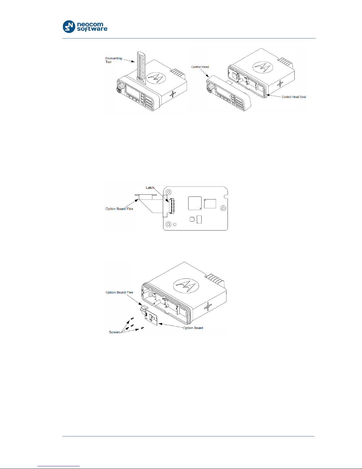
1. Insert the dismantling tool in the groove between the control head and the
radio assembly.
Page 14
Setup and Connection
11
TRBOnet Swift A200 — User Manual
Figure 3: Removing the control head
2. Press the dismantling tool under the control head to release the snap features.
Pull the control head away from the radio assembly. Remove the control head
seal.
3. Orient the flex cable (supplied in the delivery kit) so that its contacts face the
option board. Secure the connector latch to the flex cable.
Figure 4: Connecting the flex cable to the option board
4. Connect the flex cable from the option board to the main board connector.
Figure 5: Connecting the option board to the main board of the radio
5. Align the option board to the mounting holes ensuring that the flex tabs are
against the chassis alignment posts.
6. Using a T6 TORX™ driver, tighten the three screws to 0.28 N-m (2.5 lbs-in) to
secure the option board to the chassis.
7. Assemble the control head seal on the radio. Assemble the control head to the
radio chassis by aligning one side of the control head assembly tabs to one side
of the radio chassis tabs and then rotate the control head assembly until the
other side engages.
Page 15

Setup and Connection
TRBOnet Swift A200 — User Manual 12
Note: Verify that the control head seal is not pinched and not visible. If a pinch is
found, disassemble the control head, reseat the seal and reassemble the control
head.
3.3. Configuring the Radio
After you have installed the option board into your MOTOTRBO radio, configure the
radio using the MOTOTRBO CPS software.
To configure the radio:
1. Power off the radio and connect it to a USB port of a computer using the
programming cable. Power up the radio.
Note: The programming cable is not supplied in the delivery kit. Use the cable
recommended by the manufacturer of the radio.
2. Launch the MOTOTRBO CPS application.
3. Open the configuration settings of your radio by clicking Read on the Device
menu.
4. In the left pane, expand the Channels section.
5. In all zones where the radio should work through the option board, click the
channels one after another in the left pane. For each channel, select Option
Board in the right pane.
Figure 6: Enabling the use of the option board on the radio channels
6. Save the updated settings to the radio by clicking Write on the Device menu.
7. Close the application and disconnect the radio from the computer.
Page 16

Setup and Connection
13
TRBOnet Swift A200 — User Manual
3.4. Configuring the Option Board
After you have installed the option board into a MOTOTRBO radio, update the
firmware of the option board to the latest version. If the wireless connection
between Swift A200 and the radio is required, configure the NRF settings of the
option board.
To update the firmware and configure the option board:
1. Power off the radio and connect it to a USB port of a computer using the
programming cable. Power up the radio.
2. Launch the TRBOnet Swift Manager application on the computer.
Note: To install the latest version of TRBOnet Swift Manager, download the
distribution package on the website of the option board manufacturer at
www.trbonet.com.
3. In the application window, choose USB for the connection type on the menu
bar.
4. To update the firmware of the option board, follow these steps:
Expand the Tools menu and make sure that option Allow selection of
Firmware is not activated.
Figure 7: Choosing the firmware update settings
Click Update on the Device menu. The latest firmware version is loaded to
the option board automatically.
5. Open the configuration settings of the option board by clicking Read on the
Device menu. In the Searching the devices… window, point your option board
in the list and click OK. The configuration settings of your option board appear
in a separate window.
6. Click ISM transceiver settings in the left panel of the window. In the right panel,
specify the settings matching the NRF settings of your Swift A200 (page 9).
7. Write the updated settings to the option board by clicking Write on the Device
menu.
8. Close the application and disconnect the radio from the computer.
Page 17

Setup and Connection
TRBOnet Swift A200 — User Manual 14
3.5. Connecting the Radio and the LAN
When all configuration settings have been updated, connect your Swift A200 to the
local IP network. The LAN port is located on the rear panel of Swift A200.
If the radio and Swift A200 have identical NRF settings (data transfer rate and
channel), the wireless connection is established automatically as soon as both
devices are powered up.
For the wired connection between the radio and Swift A200, use the USB cable
supplied with Swift A200. Connect the cable to the RADIO (USB) connector on the
rear panel of Swift A200 and to the accessory connector of the radio.
Figure 8: The radio cable is supplied in the delivery kit
IMPORTANT: Before connecting Swift A200 to a MOTOTRBO two-way radio, power off the
radio and make sure that Swift A200 is disconnected from the power supply.
3.6. Connecting Swift A200 to Power Supply
Connect Swift A200 to the source of +12V DC (recommended) or to an AC power
supply.
3.6.1. DC Power Supply
To power Swift A200 from a DC power source, use the Micro-Fit connector supplied
in the delivery kit. The Micro-Fit plug and the wires are connected as follows: the
red wire links contact 7 (+12V) and the black wire links contact 1 (GND).
Figure 9: Micro-Fit contact positions
Page 18

Setup and Connection
15
TRBOnet Swift A200 — User Manual
To connect your Swift A200 to a DC power source:
1. Insert the Micro-Fit plug into the I/O jack on the rear panel of Swift A200.
2. Connect the other end of the red wire to terminal (+) and the black wire to
terminal (-) of a DC power unit.
3.6.2. AC Power Supply
The AC power cable is not supplied with Swift A200. To power Swift A200 from an
external AC power source, use any power cable with the 5.5mm x 2.1 mm DC plug
and the AC/DC adaptor with the DC output of +12V (positive polarity) and the input
AC voltage recommended for your region. Find all information on the label of the
power adaptor.
CAUTION: Before connecting Swift A200 to an AC power supply, test the power adaptor
to make sure it has the proper voltage and polarity. The use of a power adapter with
reverse polarity or higher voltage may cause the damage to Swift A200.
To connect your Swift A200 to an AC power source:
1. Connect the power cable through the AC/DC adaptor to the AC power inlet
located on the rear panel of your Swift A200.
2. Plug the power cable into an AC power source.
3.6.3. Reading LED indications
When powered and connected to the LAN and to a powered off radio through the
USB cable, Swift A200 shows the following diagnostic information on the display:
Similarly, when connected to a powered off radio wirelessly, Swift A200 shows the
following diagnostic information on the display:
The flashing Radio connection icon indicates that Swift A200 cannot find the
connected radio.
Figure 10: USB connection to the radio (left), Radio connection (center), and IP connection (right)
Figure 11: Wireless connection to the radio (left), Radio connection (center), and IP connection (right)
Page 19

Maintenance
TRBOnet Swift A200 — User Manual 16
Icons IP connection and USB connection to the radio (or Wireless connection to the
radio) are steady, indicating the respective connection detected by Swift A200.
Power up the connected radio. The Radio connection icon stops flashing, which
means Swift A200 has detected the connected radio.
4. Maintenance
4.1. Built-in Clock Battery Replacement
If the flashing Low battery charge icon appears on the display of the unit, you need
to replace the built-in clock battery.
Figure 12: Replacement of the battery and memory card
To replace the battery:
1. Disconnect the unit from the power supply.
2. Remove the screws and pull the front panel away from the unit. Remove the
seal.
3. Press the jacks on the rear panel to pull the board out of the unit.
4. Remove the old battery from the battery slot.
5. Insert a new CR1220 3V lithium coin battery so it matches the polarity: (+) to (+)
and (-) to (-).
6. Insert the board inside the unit, assemble the seal and the front panel on the
unit. Tighten the screws to secure the front panel to the unit.
Page 20

Maintenance
17
TRBOnet Swift A200 — User Manual
Note: Use the recommended battery type. Batteries that look similar may differ in
voltage.
4.2. Memory Card Replacement
Swift A200 is equipped with a 4 Gb microSD memory card. If necessary, you can
replace the memory card as described below.
To replace the memory card:
1. Disconnect the unit from the power supply.
2. Remove the screws and pull the front panel away from of the unit. Remove the
seal.
3. Press the jacks on the rear panel to pull the board out of the unit.
4. Unlock the microSD card holder by pulling it in the front panel’s direction.
5. Lift the card holder and remove the microSD card.
6. Insert a replacement microSD card. Ensure that the golden contacts of the
memory card face the contacts of the card holder.
7. Put down and lock the card holder, pulling it in the rear panel’s direction.
8. Insert the board inside the unit, assemble the seal and the front panel. Tighten
the screws to secure the front panel to the unit.
Note: The maximum supported memory size of a microSD card is 32 Gb.
 Loading...