

Page 1
World HQ
US Office
Internet
Telephone
Radio-over-IP Gateway
TRBOnet Swift A100
User Manual
Neocom Softwar e
8th Line 29, Vasilyev s k y Isl and
St. Petersburg, 199004, Russia
Neocom Softwar e
15200 Jog Road, Suite 202
Delray Beac h, FL 33446, USA
Email: info@trbonet.com
WWW.TRBONET.COM
EMEA: +44 203 608 0598
Americas: +1 872 222 8726
APAC: +61 28 6078325
Page 2

Notices
This document is for informational purposes only. Neocom software, Ltd offers no
warranties, express or implied, in this document.
Neocom and the Neocom logo, TRBOnet and the TRBOnet logo are either registered
trademarks or trademarks of Neocom software, Ltd.
MOTOROLA, MOTO, MOTOROLA SOLUTIONS and the Stylized M logo are trademarks
or registered trademarks of Motorola Trademark Holdings, LLC.
Microsoft, Windows, SQL Server and the .NET logo are either registered trademarks or
trademarks of Microsoft Corporation in the United States and/or other jurisdictions.
Other product or company names mentioned herein may be trademarks of their
respective owners.
© 2018 by Neocom software, Ltd. All rights reserved.
This document was last revised on April 2, 2018.
Page 3

Contents
1 Introduction ........................................................................................................................................................1
1.1 About This Document .......................................................................................................................1
1.2 About TRBOnet Swift .........................................................................................................................1
1.3 Contacts ..................................................................................................................................................1
2 About TRBOnet Swift A100 ...........................................................................................................................2
2.1 Features ..................................................................................................................................................2
2.2 Capabilities ............................................................................................................................................2
2.3 Restrictions ............................................................................................................................................3
2.4 Package Contents ...............................................................................................................................3
2.5 Specification .........................................................................................................................................4
2.6 Panels ......................................................................................................................................................5
2.7 Interior Layout ......................................................................................................................................6
2.8 LED Indication ................................................................................................................................... 10
3 Setup and Connection ................................................................................................................................. 11
3.1 MOTOTRBO Mode .......................................................................................................................... 11
3.2 Non-MOTOTRBO Mode ................................................................................................................ 18
4 TRBOnet Configuration ............................................................................................................................... 24
4.1 TRBOnet Enterprise/PLUS Configuration ................................................................................ 24
4.2 TRBOnet Watch Configuration ................................................................................................... 27
5 Maintenance .................................................................................................................................................... 29
5.1 Built-in Clock Battery Replacement .......................................................................................... 29
5.2 Memory Card Replacement ......................................................................................................... 30
6 Important Note ............................................................................................................................................... 30
ii
Page 4
Introduction
1 Introduction
1.1 About This Document
The information in this document is intended for engineers responsible for building
MOTOTRBO radio networks and programming two-way radios for end users.
The document describes in detail how to connect, set up, and maintain the
TRBOnet Swift A100 hardware radio-over-IP gateway.
1.2 About TRBOnet Swift
TRBOnet Swift is a family of hardware products designed by Neocom Software
Solutions, Ltd for MOTOTRBO radio networks. The Swift family hardware is
presented by the RoIP gateways A100 and A200, and the option board ST002.
For more information about the TRBOnet Swift family products, refer to our website.
1.3 Contacts
Region Phone Email & Support
EMEA +44 203 608 0598
Americas +1 872 222 8726
APAC +61 28 607 8325
info@trbonet.com
commercial inquiries
support@trbonet.com — technical support
http://kb.trbonet.com — online knowledge
base
— general and
1
Page 5

2 About TRBOnet Swift A100
TRBOnet Swift A100 (also referred to as the "A100 gateway") is a hardware radioover-IP gateway intended to connect a control radio to TRBOnet Server. The radio
can transfer voice and data to one or multiple connected TRBOnet Servers over IP.
2.1 Features
Designed for DM4000 (EMEA), XPR 5000 (NAR), DGM 5000, DGM 8000
(LACR), and XiR M8600i, XiR M8600, XiR M6660 (APAC) series mobile radios
Compatible with digital and analog radios by Motorola
Wired connection to a mobile radio via the service cable
Transfer of voice and data from/to a radio over IP
Support for multiple (up to 4) connected TRBOnet Servers
Control of a connected MOTOTRBO radio (power on/off, restart)
Self-diagnostics and alarm notifications over IP
2U, 19" rack mount design
Power supply 110/220V AC
Compatible with backup battery units
Forced-air cooling with integrated fans
Automatic temperature monitoring and control
4 input/output contacts for external hardware, such as sensors, etc.
2.2 Capabilities
2.2.1 Radio-over-IP gateway
Connected to a mobile radio and to the LAN, the A100 gateway acts as a radio-overIP gateway between the mobile radio and TRBOnet Server(s), providing the following
features:
Voice and data communications between a MOTOTRBO radio and TRBOnet
over IP.
Voice communications between a non-MOTOTRBO radio and TRBOnet over
IP.
Automatic power-on/off of a MOTOTRBO radio upon turning on/off the A100
gateway.
Broadcasting outgoing IP traffic (voice, data, alarm notifications) to multiple
connected TRBOnet Servers.
2.2.2 Temperature control system
The A100 gateway is equipped with two fans and a controller to keep the hardware
at its optimum operating temperatures. The cooling system has the following
features:
Performs continuous temperature monitoring inside the unit.
Automatically activates/deactivates the fans and controls their speed, thus
keeping the appropriate temperature.
Sends an alarm notification to all connected TRBOnet Servers when a
temperature threshold is exceeded.
2 TRBOnet Swift A100 – User Manual
Page 6
About TRBOnet Swift A100
2.2.3 Battery backup power system
The A100 gateway features a built-in power supply unit that accepts an AC input and
produces a DC voltage to the IP controller, the temperature control system, and the
connected radio. The power supply system can also be enhanced with a reserve
battery (not included, 12V-nominal battery) to support the battery backup feature so
that if the AC power fails, the A100 gateway will be powered from a DC battery.
The battery backup power system has the following features:
Controls the power supply and switches to the backup battery automatically if
the AC power fails.
Sends an alarm notification to all connected TRBOnet Servers in case of power
loss or when switching to the backup power supply.
Charges the battery while operating from the AC power supply.
2.3 Restrictions
It is prohibited to install any Radio-over-IP gateways in the same subnet as
trunked repeaters (applies to Capacity Plus and Linked Capacity Plus).
2.4 Package Contents
The package contents of TRBOnet Swift A100 include the following items:
Item Description Quantity
TRBOnet Swift A100 The hardware unit with an integrated IP controller,
TRBOnet Swift ST002 The option board for a MOTOTRBO radio.
Power cable The cable to connect the unit to 110/220V AC. 1
Ring terminal The ring connector for the ground cable. 1
Screw kit The screw kit for mounting the unit in a 19" 2U rack. 1
Spare fuses 3A (5x20) and 10A (6x30) 2
6-pin connector plug The connector plug used to connect the A100 gateway
5-pin connector plug The connector plug used to connect the A100 gateway
Table 1: TRBOnet Swift A100 package contents
1
power supply unit, and temperature control system.
1
The flex cable to connect the option board to the main
board of a MOTOTRBO radio. The screw kit.
1
to a non-MOTOTRBO radio.
1
to external hardware.
Passport Technical documentation for TRBOnet Swift Agent
A100.
1
3
Page 7

Weight
7 kg
Storage temperature
-40 °C to +85 °C
Relative humidity, max
85% at +40 °C
Power input voltage
100-240 V AC
Power current consumption, max
2.5 A
capacity 12-40 Ah
built-in power source, max
2.5 Specification
Table 2: TRBOnet Swift A100 Specification
Dimensions 485 x 370 x 88 mm
Operational temperature -10 °C to +45 °C
Ingress protection rating IP20
Power input frequency 50/60 Hz
Emergency power supply (reserve battery) 12-14 V DC
Battery type
Lead-acid battery, nominal voltage 12 V, recommended
Current consumption from reserve battery,
max
Charge current of reserve battery from
Display
Interfaces
Bandwidth
10 A
0.5 A
15 kbps for one control connection
* The OLED is located on the IP controller.
** TRBOnet Enterprise/PLUS of version 5.2.5 and higher is required.
4 TRBOnet Swift A100 – User Manual
Page 8
About TRBOnet Swift A100
1
1
2
7 3 8 2 4 5 6
9
10
11
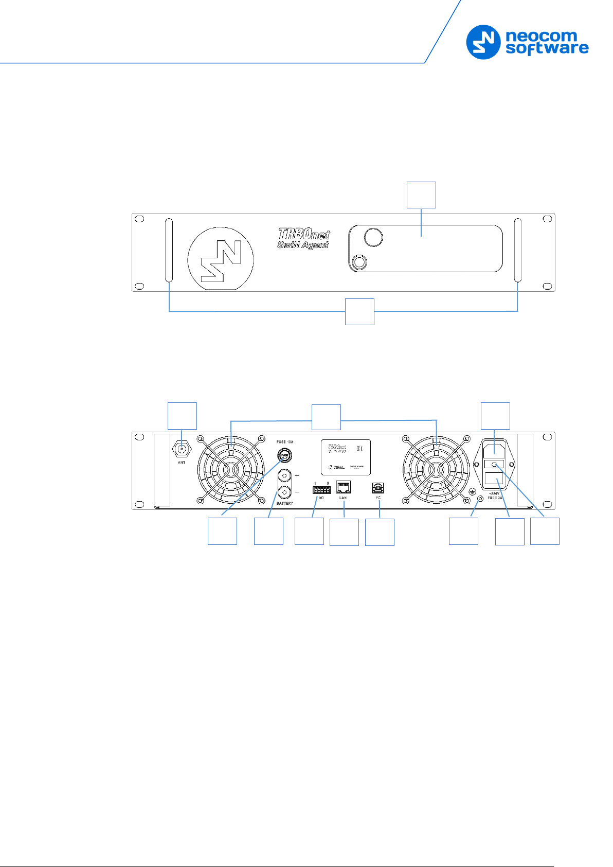
2.6 Panels
TRBOnet Swift A100 comes in a metal case.
2.6.1 Front Panel
The front panel features a slot for a two-way mobile radio (1) and two handles (2) for
transportation and mounting.
2.6.2 Rear Panel
The rear panel of the unit has two built-in fans (3), several connectors, and a power
switch (8).
1. External antenna socket
2. External battery (+)/(-) terminals
3. Two built-in fans
4. Input/Output pins
5. LAN port
6. USB port, type B
7. Earth ground socket
8. Power switch
9. AC power socket
10. Fuse block 3A (5x20), 220V AC
11. Fuse block 10A (6x30), 12V battery
5
Page 9
1 3 5
6 7 8
4
2
9
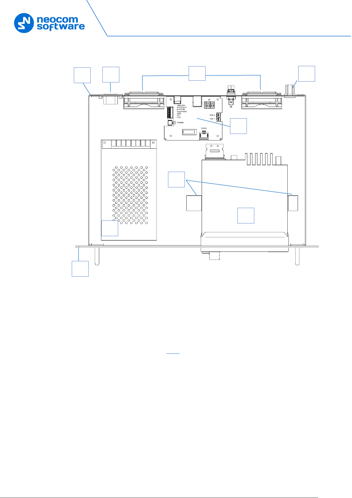
2.7 Interior Layout
1. Front panel
2. Rear panel
3. Power supply unit
4. AC power socket and switch
5. Radio (user supplied)
6. Brackets for the radio
7. IP controller (see section 2.7.1
8. External antenna socket
9. Built-in fans
)
6 TRBOnet Swift A100 – User Manual
Page 10
About TRBOnet Swift A100
1 2 3 4 5 6 7 8 9
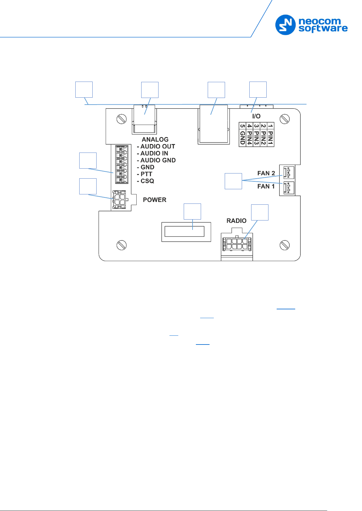
2.7.1 IP Controller
1. Rear panel
2. USB port, type B
3. LAN port
4. Input/Output terminal block (for pin assignment, see section 2.7.1.1
5. Analog terminal block (see section 3.2.1)
6. Power terminal block
7. LED Display (see section 2.8
8. Radio terminal block (see section 3.1.2)
9. Fan terminal blocks
)
)
7
Page 11

Input/Output terminal block
I/O terminal block pinout:
1 – PIN1
2 – PIN2
3 – PIN3
4 – PIN4
5 – GND
Radio terminal block
RADIO terminal block pinout:
1 – D- USB
2 – +VBUS USB
3 – ---
4 – IGNITION (radio on)
5 – D+ USB
6 – GND
7 – GND
8 – SWB (radio detect)
8 TRBOnet Swift A100 – User Manual
Page 12

About TRBOnet Swift A100
Analog terminal block
ANALOG terminal block pinout:
1 – CSQ
2 – PTT
3 – GND
4 – AUDIO GND
5 – AUDIO IN
6 – AUDIO OUT
Power terminal block
POWER terminal block pinout:
1 – GND
2 – GND
3 – AC-GOOD (AC detection)
4 – V-IN (power)
9
Page 13

2.8 LED Indication
Icon State
Radio connection
Flashing icon: The radio is disconnected or powered off.
Radio TX
Radio RX
IP connection
The number next to the icon indicates how many TRBOnet Servers are connected.
Flashing icon: the A100 gateway is not connected to an IP network.
Incoming/outgoing data indicator
Table 3: LED icons
USB connection to the radio
Memory card
The memory card is not detected.
Low battery charge
Battery replacement is required.
Built-in clock not set
The built-in clock is not set. Update of the device configuration or battery replacement is
required.
10 TRBOnet Swift A100 – User Manual
Page 14

Setup and Connection
3 Setup and Connection
TRBOnet Swift A100 can operate in the MOTOTRBO mode or in the nonMOTOTRBO mode. The choice of the operation mode depends on the type of the
connected radio.
Table 4: A100 operation modes
Radio Operation mode Connection with the radio
Motorola MOTOTRBO MOTOTRBO Wired (USB)
Non-MOTOTRBO Non-MOTOTRBO Wired (audio)
To configure your A100 gateway, download the Swift Utilities Pack (version 1.7 and
higher) from www.trbonet.com
your computer. Then set up and connect your A100 gateway for operation in the
preferred mode. Find the details in the following sections:
and install the TRBOnet Swift CPS software tool on
3.1 MOTOTRBO Mode (page 11)
3.2 Non-MOTOTRBO Mode (page 18)
3.1 MOTOTRBO Mode
To configure the A100 gateway to operate in the MOTOTRBO mode, follow the
steps in Table 5.
Table 5: Steps to configure the A100 gateway to operate in the MOTOTRBO mode
# Step Refer to:
1 Install the option board into the MOTOTRBO
radio
2 Install and connect the MOTOTRBO radio 3.1.2, Installing and Connecting the Radio
3 Configure the MOTOTRBO radio 3.1.3, Configuring the Radio
4 Configure the option board 3.1.4, Configuring the Option Board
5 Configure the A100 gateway 3.1.5, Configuring the A100
3.1.1 Installing the Option Board
3.1.1, Installing the Option Board
The package contents include an option board that you need to install into a
MOTOTRBO radio.
To install the option board into the radio:
1. Insert the dismantling tool in the groove between the control head and the
radio assembly.
11
Page 15

Figure 1: Removing the control head
2. Press the dismantling tool under the control head to release the snap
features. Pull the control head away from the radio assembly. Remove the
control head seal.
3. Orient the flex cable (included in the package contents) so that it contacts
face the option board. Secure the connector latch to the flex cable.
Figure 2: Connecting the flex cable to the option board
4. Connect the flex cable from the option board to the main board connector.
Figure 3: Connecting the option board to the main board of the radio
5. Align the option board to the mounting holes ensuring that the flex tabs are
against the chassis alignment posts.
6. Using a T6 TORX™ driver, tighten the three screws to 0.28 N-m (2.5 lbs-in) to
secure the option board to the chassis.
7. Assemble the control head seal on the radio. Assemble the control head to
the radio chassis by aligning one side of the control head assembly tabs to
one side of the radio chassis tabs and then rotate the control head assembly
until the other side engages.
12 TRBOnet Swift A100 – User Manual
Page 16

Setup and Connection
Note: Verify that the control head seal is not pinched and not visible. If a pinch is
found, disassemble the control head, reseat the seal and reassemble the
control head.
3.1.2 Installing and Connecting the Radio
Now install your MOTOTRBO radio into the A100 gateway and connect it to all
required components inside the unit.
1. Remove the screws and lift the top cover of the unit.
2. Insert the radio into the slot on the front panel of the unit, orienting the
radio’s back panel inside the unit. Use the screws of the proper size to secure
the radio in the unit.
Figure 4: Installing a MOTOTRBO radio into the unit
3. Perform the following connections:
a. Connect the radio to the IP controller with a service cable. The service
cable is included in the package contents.
b. Connect the radio to the power supply. The black-and-red power cable is
already connected to the integrated power supply unit.
c. Connect the RF antenna to the mobile radio. The antenna cable is
included in the package contents.
4. Reinstall the top cover and secure it with the screws.
13
Page 17

3.1.3 Configuring the Radio
Now configure your MOTOTRBO radio using the MOTOTRBO CPS software.
To configure the radio:
1. Power off the A100 gateway. Connect the programming cable to the radio
and to a USB port of your computer. Power up the A100 gateway.
2. Launch the MOTOTRBO CPS software on your computer.
3. Open the configuration settings of your radio by clicking Read on the Device
menu.
4. In the left pane, expand the Channels section.
5. For all channels on which the radio should work through the option board,
select Option Board in the right pane (Figure 5).
6. Save the updated settings to the radio by clicking Write on the Device menu.
7. Close the application and disconnect the radio from the computer.
Figure 5: Enabling the option board capability
3.1.4 Configuring the Option Board
To configure the option board:
1. Power off the A100 gateway. Connect the programming cable to the radio
and to a USB port of your computer. Power up the A100 gateway.
2. Launch TRBOnet Swift CPS on your computer. In the main window, select USB
as the programming interface (Figure 6, page 15).
3. On the Device menu, click Update Firmware.
14 TRBOnet Swift A100 – User Manual
Page 18

Setup and Connection
4. In the Firmware update USB window, make sure your Swift ST002 is selected.
5. From the Mode drop-down list, select "USB transfer for Agent".
6. From the Update to drop-down list, select the latest firmware version.
7. Click Update.
3.1.5 Configuring the A100 Gateway
To configure the A100 gateway:
1. Launch TRBOnet Swift CPS. In the main window's bottom bar, select USB as
an interface for device programming (Figure 6). Connect the programming
cable to a USB port of your computer.
Figure 6: Selecting the USB connection for programming
If you prefer to program your A100 gateway using the LAN connection, select
LAN as the programming interface and connect the A100 gateway to the LAN
and to the power supply.
2. Update the firmware of your A100 gateway:
a. On the Tools menu, click Options. In the right pane, make sure that the
Enable changing device mode option is switched on (Figure 7).
15
Page 19

Figure 7: The device mode change is enabled
b. On the Device menu, click Update Firmware. If you use the LAN
connection for programming, specify the IP address of your A100 gateway
and click Connect.
c. In the Firmware update window, make sure your A100 gateway is
selected. From the Mode drop-down list, select "USB RoIP Gateway".
d. From the Update to drop-down list, select the latest firmware version.
Click Update.
Figure 8: Updating firmware on the A100 gateway connected through USB
3. To open the configuration of your A100 gateway, click the Read button, or
open the Device menu and click Read.
If you use the LAN connection, the Read LAN window appears. Specify the
IP address of your A100 gateway and click Read.
If you use the USB connection and the Select device window appears,
point your device.
The configuration settings appear in a separate tab.
4. Click Network Settings in the left panel.
16 TRBOnet Swift A100 – User Manual
Page 20

Setup and Connection
Figure 9: Configuring the IP network settings of the A100 gateway
In the right panel, specify the following settings:
IP Address: The IP address assigned to your A100 gateway.
Subnet Mask: The mask of the subnet to which the A100 gateway
belongs.
Default Gateway: The default gateway of the IP network.
MAC Address: The default network address of the A100 gateway.
5. Click I/O Settings in the left panel.
Figure 10: Configuring I/O pins
17
Page 21

In the right panel, configure the I/O pins of A100 gateway that are connected
to external hardware (Figure 10). For each connected I/O pin, expand the
menu and select the logical pin in TRBOnet:
Specify the active level of the signal and other I/O pin settings.
Note: For TRBOnet software to display the states of the A100 pins, configure
TRBOnet software as described in section 4 TRBOnet Configuration
(page 24).
If a physical pin is not connected, leave it unassigned.
6. To save the configuration on your A100 gateway, click the Write button or
open the Device menu and click Write.
3.2 Non-MOTOTRBO Mode
To configure TRBOnet Swift A100 to operate in the non-MOTOTRBO mode, follow
the steps in Table 6.
Table 6: High-level steps to configure TRBOnet Swift A100 to operate in the non-MOTOTRBO mode
# Step Refer to:
1 Assemble the service cable. 3.2.1 Assembling the Service Cable
2 Install and connect the non-MOTOTRBO radio 3.2.2 Installing and Connecting the Radio
3 Configure the non-MOTOTRBO radio 3.2.3 Configuring the Radio
4 Configure the A100 gateway 3.2.4 Configuring the A100 Gateway
3.2.1 Assembling the Service Cable
TRBOnet Swift A100 and a non-MOTOTRBO radio can be connected using the
service cable. To assemble the service cable, use a 6-pin connector plug (included in
the package contents), a wire kit, and a radio connector plug.
Note: The radio connector plug is not included in the package contents. Contact
the manufacturer of your radio or a sales representative to get the plug
compatible with the service connector of your radio.
To assemble the service cable:
1. Connect the wires between the 6-pin connector plug and the radio connector
plug to implement the following required links:
Table 7: Service cable pinout
A100 6-pin connector Radio connector
AUDIO OUT EXT MIC AUDIO (TX AUDIO)
AUDIO IN RX AUDIO
AUDIO GROUND GND
PTT PTT
18 TRBOnet Swift A100 – User Manual
Page 22

Setup and Connection
A100 6-pin connector Radio connector
CSQ CSQ DETECT
2. (Optional) Add two wires between the A100 Radio terminal block and the
radio connector plug to implement additional features.
A100 Radio terminal block Radio connector
PIN 4 IGNITION SENSE
PIN 8 SWB+
3. (Optional) Connect external hardware (sensors, controllers) to the
Input/Output pins of the A100 gateway.
Example
The following diagram shows how to assemble the service cable for a Motorola
CM140 two-way radio.
Figure 11: Connecting wires to the A100 6-pin connector plug and to the radio connector plug
When the service cable is finished and pins are configured on the radio and on the
A100 gateway accordingly, connect your A100 gateway to the radio and to external
hardware (if necessary).
Note: Before connecting the A100 gateway, make sure that the radio is powered off
and that the A100 gateway and all external hardware (if any to be connected)
is disconnected from the power supply.
19
Page 23

3.2.2 Installing and Connecting the Radio
Now install your non-MOTOTRBO radio into the A100 gateway and connect it to all
required components inside the unit.
1. Remove the screws and lift the top cover of the unit.
2. Insert the radio into the slot on the front panel of the unit, orienting the
radio’s back panel inside the unit. Use the screws of the proper size to secure
the radio in the unit.
Figure 12: Installing a non-MOTOTRBO radio into the unit
3. Perform the following connections:
a. Connect the radio to the IP controller with the service cable you have
assembled (see section 3.2.1, Assembling the Service Cable
b. Connect the radio to the power supply. The black-and-red power cable is
already connected to the integrated power supply unit.
c. Connect the RF antenna to the mobile radio. The antenna cable is
included in the package contents.
4. Reinstall the top cover and secure it with the screws.
3.2.3 Configuring the Radio
After you have assembled the service cable, configure your radio to use the radio
connector pins that are coupled with the pins of the A100 gateway. Use the radio
programming software provided by the manufacturer of the radio.
Program the GPIO pins of your radio as described in the documentation supplied by
the manufacturer of the radio.
).
20 TRBOnet Swift A100 – User Manual
Page 24

Setup and Connection
3.2.4 Configuring the A100 Gateway
To configure the A100 gateway:
1. Launch TRBOnet Swift CPS. In the main window, select USB as an interface for
device programming at the bottom (Figure 6, page 15). Connect the
programming cable to the USB type B port of the A100 gateway and to a USB
port of your computer.
If you prefer to program your A100 gateway using the LAN connection, select
LAN as the programming interface and connect the A100 gateway to the LAN
and to the power supply.
2. (Recommended) Update the firmware of your A100 gateway:
a. On the Tools menu, click Options. In the right pane, make sure that the
Enable changing device mode option is switched on (Figure 7, page 16).
Figure 13: Updating firmware on the A100 gateway connected through USB
b. On the Device menu, click Update Firmware. If you use the LAN
connection for programming, specify the IP address of your A100 gateway
and click Connect.
c. In the Firmware update window, make sure your A100 gateway is
selected. From the Mode drop-down list, select "Analog RoIP Gateway".
d. From the Update to drop-down list, select the latest firmware version.
Click Update.
3. To open the configuration of your A100 gateway, click the Read button, or
open the Device menu and click Read.
If you use the LAN connection, the Read LAN window appears. Specify the
IP address of your A100 gateway and click Read.
If you use the USB connection and the Select device window appears,
point your device.
The configuration settings appear on a separate tab.
4. Click Network Settings in the left panel. Specify the following settings:
IP Address: The IP address assigned to your A100 gateway.
Subnet Mask: The mask of the subnet to which the A100 gateway
belongs.
Default Gateway: The default gateway of the IP network.
MAC Address: The MAC address of your A100 gateway.
21
Page 25

5. Click I/O Settings in the left panel. In the right panel, configure the I/O
connector pins:
For I/O pins connected to the service cable, specify the function (PTT
Output, CSQ Input, other), the active level, and other I/O pin settings
(Figure 14).
Note: The radio connector pins must be configured to use the matching
function and active level. For more details, refer to section 3.2.3
Configuring the Radio (page 20).
If any I/O pins are connected to external hardware, configure the A100
gateway to send the states of these pins to TRBOnet software. For each
I/O pin connected by external hardware, expand the menu and select the
logical pin in TRBOnet:
Specify the active level of the signal and other I/O pin settings.
Note: For TRBOnet software to display the pin states received from the A100
gateway, configure TRBOnet software as described in section
4 TRBOnet Configuration (page 24).
Figure 14: Configuring I/O pins connected to the service cable
22 TRBOnet Swift A100 – User Manual
Page 26

Setup and Connection
6. Click Audio Settings in the left panel. In the right panel (Figure 15), do the
following:
Use the sliders to adjust the level of the input and output audio signal in
the range of -42Db to 20 Db.
To raise the level of the input audio signal, adjust the amplifier.
Figure 15: Configuring the audio signal
7. To save the configuration to your A100 gateway, click the Write button, or
open the Device menu and click Write.
23
Page 27

4 TRBOnet Configuration
This section describes how to configure TRBOnet Server and TRBOnet Dispatch
Console, so that the operator can see and manage the physical I/O pins of the A100
gateway.
In the A100 configuration, the physical I/O pins are mapped to the logical pins of
TRBOnet (Figure 10).
To complete the I/O pin configuration in TRBOnet, read the following sections:
4.1 TRBOnet Enterprise/PLUS Configuration (page 24
4.2 TRBOnet Watch Configuration (page 27)
4.1 TRBOnet Enterprise/PLUS Configuration
In this example, TRBOnet Swift A100 is registered as a radio system in the TRBOnet
Enterprise (PLUS) Server configuration (Figure 16).
Figure 16: Registering the A100 gateway as a radio system
)
Launch the TRBOnet Dispatch Console and click Voice Dispatch in the left pane. If
registered correctly, your A100 gateway appears on the Radio Interface tab with
the green (“connected”) icon (Figure 17).
Figure 17: The RoIP gateway “TRBOnet Swift A100” is connected properly
24 TRBOnet Swift A100 – User Manual
Page 28

TRBOnet Configuration
To configure pins:
1. In the TRBOnet Dispatch Console, click Administration and Radio Systems in
the left pane (Figure 18, step 1 and 2).
2. In the right pane, the list of the registered radio systems appears. Double-click
the radio system associated with your A100 gateway (Figure 18, step 3).
3. In the popup window, click the Channels tab. Double-click the channel
(Figure 18, step 4), or select it and click Properties. Another popup window
appears.
4. In the second popup window, click the Master Control tab and configure
pins.
Figure 18: Configuring the A100 gateway pins in TRBOnet Dispatch Console
Under Control states, select the logical input pins that you have mapped
in the configuration of your A100 gateway (see section 3.1.1
). Do not
select pin 0. For each selected pin:
Double-click the value in the Name field and enter a descriptive pin
name.
In the Value field, you see the pin states (ON and OFF) and their
displayed values (also ON and OFF by default). If necessary, doubleclick the value in the second column and enter a custom name of the
pin state.
In the Status field, select Alarm for the TRBOnet Dispatch Console
operator to see an alarm box when the given pin state is detected.
25
Page 29

Under Commands, select the logical output pins that you mapped to the
physical pins of your A100 gateway (see section 3.1.1
). For each selected
pin, specify a descriptive name. In the Value ON and Value OFF fields,
double-click the value and enter a custom name of the command.
5. Click OK and again OK.
To see the configured pins, click Voice Dispatch in the left pane. Click the green
icon in the PTT box corresponding to your A100 gateway (Figure 19).
Figure 19: Opening the A100 pin states
A pop-up window appears displaying the pin states:
Figure 20: Pin states
The temperature is measured inside the unit and transmitted to TRBOnet by default,
no additional configuration is required. The fan speeds for each of the two coolers
are displayed in revolutions per minute.
Input and output pins appear with their custom names. The input pin states are
read-only. The operator can change the output pin states by clicking a respective
command next to the pin name (ON and OFF under Outputs in Figure 20). Or, the
operator can right-click the green icon in the PTT box of the A100 gateway and
change the output pin states from the popup menu (Figure 21).
26 TRBOnet Swift A100 – User Manual
Page 30

TRBOnet Configuration
Figure 21: Changing the output pin states
4.2 TRBOnet Watch Configuration
The I/O pins of TRBOnet Swift A100 are supported in TRBOnet Watch 2.5 and later
versions. In this example, the A100 gateway is registered as a radio system in the
TRBOnet Watch Server configuration (Figure 22).
Figure 22: Registering TRBOnet Swift A100 as a radio system
Enable the Input Pins feature and configure pins as follows:
Select the logical input pins (PIN 1 through PIN 4) that you have mapped in
the configuration of your A100 gateway (see section 3.1.5
). Leave PIN 0
unselected.
If needed, enter a descriptive name for each input pin. Otherwise, the console
will display the default pin names (PIN1, PIN2, and so on).
27
Page 31

For each pin, expand the Pin value menu and select the active level exactly as
specified in the A100 configuration (see section 3.1.5
).
After you apply the changes, launch the TRBOnet Watch console and click
Live Monitor in the left pane. You can see the states of the connected A100 pins on
the Diagnostics tab and on the Physical GPIO Pins tab.
Figure 23: TRBOnet Swift A100 pin states on the Diagnostics tab
The State panel shows all pins (input and output) that are connected to external
hardware.
The green icon indicates the active level on the pin.
The red icon indicates an inactive pin.
Point the mouse cursor at the pin in the State panel to see the detailed information
about the pin (Figure 23).
28 TRBOnet Swift A100 – User Manual
Page 32

Maintenance
A
B
5 Maintenance
5.1 Built-in Clock Battery Replacement
If the flashing Low battery charge icon appears on the display of the unit, you need
to replace the built-in clock battery.
Figure 24: Replacement of the battery and memory card
To replace the battery:
1. Disconnect the unit from the power supply.
2. Undo the screws and remove the cover from the IP controller.
3. Remove the old battery from the battery slot.
4. Insert a new CR1220 3V lithium coin battery so it matches the polarity.
5. Replace the cover and tighten the screws.
Note: Use the recommended battery type. Batteries that look similar may differ in
voltage.
29
Page 33

5.2 Memory Card Replacement
If necessary, you can replace the memory card as described below.
To replace the memory card:
1. Disconnect the unit from the power supply.
2. Undo the screws and remove the cover from the IP controller.
3. Unlock the microSD card holder by pulling it in direction A.
4. Lift the card holder and remove the microSD card.
5. Insert a replacement microSD card. Ensure that the golden contacts of the
memory card face the contacts of the microSD card holder.
6. Put down and lock the card holder by pulling it in direction B.
7. Replace the cover and tighten the screws.
Note: The maximum supported memory size of a microSD card is 32 Gb.
6 Important Note
The manufacturer reserves the right to make changes and/or improvements in
designs and dimensions without notice and without incurring obligation.
30 TRBOnet Swift A100 – User Manual
 Loading...