

TRAYNOR YS1081 User Manual

MODEL TYPE: YS1081
Acoustic Master Standard
Acoustic-GuitAr Amplifier

The exclamation point within an equilatereal triangle is
intended to alert the user to the presence of important
operating and maintenance (servicing) instructions in
the literature accompanying the appliance.
Le point d’exclamation à l’intérieur d’un triangle équilatéral
est prévu pour alerter l’utilisateur de la présence
d’instructions importantes dans la littérature accompagnant l’appareil en ce qui concerne l’opération et la
maintenance de cet appareil.
This lightning flash with arrowhead symbol, within
an equilateral triangle, is intended to alert the user to
the presence of uninsulated “dangerous voltage”
within the product’s enclosure that may be of sufficient
magnitude to constitute a risk of electric shock to persons.
Ce symbole d’éclair avec tête de flèche dans un triangle
équilatéral est prévu pour alerter l’utilisateur de la présence d’un
« voltage dangereux » non-isolé à proximité de l’enceinte du
produit qui pourrait être d’ampleur suffisante pour présenter
un risque de choque électrique.
IMPORTANT SAFETY INSTRUCTIONS
safety-4v7 • May 7/2008
CAUTION: TO REDUCE THE RISK OF ELECTRIC
SHOCK, DO NOT REMOVE COVER (OR BACK).
NO USER SERVICEABLE PARTS INSIDE.
REFER SERVICING TO QUALIFIED
SERVICE PERSONNEL.
FOLLOW ALL INSTRUCTIONS SUIVEZ TOUTES LES INSTRUCTIONS
Instructions pertaining to a risk of fire,
electric shock, or injury to a person
Read Instructions: The Owner’s Manual should be read and understood before operation
of your unit. Please, save these instructions for future reference and heed all warnings.
Clean only with dry cloth.
Packaging: Keep the box and packaging materials, in case the unit needs to be
returned for service.
Warning: To reduce the risk or fire or electric shock, do not expose this apparatus to rain or
moisture. Do not use this apparatus near water!
Warning: When using electric products, basic precautions should always be followed,
including the following:
Power Sources
Your unit should be connected to a power source only of the voltage specified in the
owners manual or as marked on the unit. This unit has a polarized plug. Do not use
with an extension cord or receptacle unless the plug can be fully inserted. Precautions should be taken so that the grounding scheme on the unit is not defeated. An
apparatus with CLASS I construction shall be connected to a Mains socket outlet with
a protective earthing ground. Where the MAINS plug or an appliance coupler is used
as the disconnect device, the disconnect device shall remain readily operable.
Hazards
Do not place this product on an unstable cart, stand, tripod, bracket or table. The
product may fall, causing serious personal injury and serious damage to the product.
Use only with cart, stand, tripod, bracket, or table recommended by the manufacturer
or sold with the product. Follow the manufacturer’s instructions when installing the
product and use mounting accessories recommended by the manufacturer. Only use
attachments/accessories specified by the manufacturer
Note: Prolonged use of headphones at a high volume may cause
health damage on your ears.
The apparatus should not be exposed to dripping or splashing water; no objects
filled with liquids should be placed on the apparatus.
Te rminals marked with the “lightning bolt” are hazardous live; the external wiring
connected to these terminals require installation by an instructed person or the use of
ready made leads or cords.
Ensure that proper ventilation is provided around the appliance. Do not install near
any heat sources such as radiators, heat registers, stoves, or other apparatus
(including amplifiers) that produce heat.
No naked flame sources, such as lighted candles, should be placed on the apparatus.
Power Cord
Do not defeat the safety purpose of the polarized or grounding-type plug. A polarized plug
has two blades with one wider than the other. A grounding type plug has two blades and a
third grounding prong. The wide blade or the third prong are provided for your safety. If the
provided plug does not fit into your outlet, consult an electrician for replacement of the
obsolete outlet. The AC supply cord should be routed so that it is unlikely that it will be
damaged. Protect the power cord from being walked on or pinched particularly at plugs. If
the AC supply cord is damaged DO NOT OPERATE THE UNIT. T o completely disconnect
this apparatus from the AC Mains, disconnect the power supply cord plug from the AC
receptacle. The mains plug of the power supply cord shall remain readily operable.
Unplug this apparatus during lightning storms or when unused for long periods of time.
Service
The unit should be serviced only by qualified service personnel. Servicing is required
when the apparatus has been damaged in any way, such as power-supply cord or plug is
damaged, liquid has been spilled or objects have fallen into the apparatus, the apparatus
has been exposed to rain or moisture, does not operate normally, or has been dropped.
AVIS: AFIN DE REDUIRE LES RISQUE DE CHOC
ELECTRIQUE, N’ENLEVEZ PAS LE COUVERT (OU LE
PANNEAU ARRIERE) NE CONTIENT AUCUNE PIECE
REPARABLE PAR L’UTILISATEUR.
CONSULTEZ UN TECHNICIEN QUALIFIE
POUR L’ENTRETIENT
Instructions relatives au risque de feu,
choc électrique, ou blessures aux personnes
Veuillez Lire le Manuel: Il contient des informations qui devraient êtres comprises avant
l’opération de votre appareil. Conservez. Gardez S.V .P . ces instructions pour consultations
ultérieures et observez tous les avertissements.
Nettoyez seulement avec le tissu sec.
Emballage: Conservez la boite au cas ou l’appareil devait être retourner pour réparation.
Avertissement: Pour réduire le risque de feu ou la décharge électrique, n'exposez pas
cet appareil à la pluie ou à l'humidité. N’utilisez pas cet appareil près de l’eau!
Attention: Lors de l’utilisation de produits électrique, assurez-vous d’adhérer à des
précautions de bases incluant celle qui suivent:
Alimentation
L’ appareil ne doit être branché qu’à une source d’alimentation correspondant au
voltage spécifié dans le manuel ou tel qu’indiqué sur l’appareil. Cet appareil est équipé
d’une prise d’alimentation polarisée. Ne pas utiliser cet appareil avec un cordon de
raccordement à moins qu’il soit possible d’insérer complètement les trois lames. Des
précautions doivent êtres prises afin d’eviter que le système de mise à la terre de
l’appareil ne soit désengagé. Un appareil construit selon les normes de CLASS I
devrait être raccordé à une prise murale d’alimentation avec connexion intacte de mise
à la masse. Lorsqu’une prise de branchement ou un coupleur d'appareils est utilisée
comme dispositif de débranchement, ce dispositif de débranchement devra demeurer
pleinement fonctionnel avec raccordement à la masse.
Risque
Ne pas placer cet appareil sur un chariot, un support, un trépied ou une table instables.
L’appareil pourrait tomber et blesser quelqu’un ou subir des dommages importants.
Utiliser seulement un chariot, un support, un trépied ou une table recommandés par le
fabricant ou vendus avec le produit. Suivre les instructions du fabricant pour installer
l’appareil et utiliser les accessoires recommandés par le fabricant. Utilisez seulement
les attachements/accessoires indiqués par le fabricant
Note: L'utilisation prolongée des écouteurs à un volume élevé peut
avoir des conséquences néfastes sur la santé sur vos oreilles. .
Il convient de ne pas placer sur l’appareil de sources de flammes nues, telles que
des bougies allumées.
L’appeil ne doit pas être exposé à des égouttements d’eau ou des éclaboussures
et qu’aucun objet rempli de liquide tel que des vases ne doit être placé sur l’appareil.
Assurez que lappareil est fourni de la propre ventilation. Ne procédez pas à
l’installation près de source de chaleur tels que radiateurs, registre de chaleur, fours
ou autres appareils (incluant les amplificateurs) qui produisent de la chaleur.
Les dispositifs marqués d’une symbole “d’éclair” sont des parties dangereuses
au toucher et que les câblages extérieurs connectés à ces dispositifs de
connection extérieure doivent être effectivés par un opérateur formé ou en utilisant
des cordons déjà préparés.
Cordon d’Alimentation
Ne pas enlever le dispositif de sécurité sur la prise polarisée ou la prise avec tige de
mise à la masse du cordon d’alimentation. Une prise polarisée dispose de deux lames
dont une plus large que l’autre. Une prise avec tige de mise à la masse dispose de
deux lames en plus d’une troisième tige qui connecte à la masse. La lame plus large ou
la tige de mise à la masse est prévu pour votre sécurité. La prise murale est désuète si
elle n’est pas conçue pour accepter ce type de prise avec dispositif de sécurité. Dans
ce cas, contactez un électricien pour faire remplacer la prise murale. Évitez
d’endommager le cordon d’alimentation. Protégez le cordon d’alimentation. Assurezvous qu’on ne marche pas dessus et qu’on ne le pince pas en particulier aux prises.
N’UTILISEZ PA S L’APPAREIL si le cordon d’alimentation est endommagé. Pour
débrancher complètement cet appareil de l’alimentation CA principale, déconnectez le
cordon d’alimentation de la prise d’alimentation murale. Le cordon d’alimentation du
bloc d’alimentation de l’appareil doit demeurer pleinement fonctionnel.
Débranchez cet appareil durant les orages ou si inutilisé pendant de longues périodes.
Service
Consultez un technicien qualifié pour l’entretien de votre appareil. L'entretien est
nécessaire quand l'appareil a été endommagé de quelque façon que se soit. Par exemple
si le cordon d’alimentation ou la prise du cordon sont endommagés, si il y a eu du liquide
qui a été renversé à l’intérieur ou des objets sont tombés dans l'appareil, si l'appareil a été
exposé à la pluie ou à l'humidité, si il ne fonctionne pas normalement, ou a été échappé.
S2125A
Ch 1
Ch 2
Feedba ck
Not ch
Ch 1
INPUT
Ch 2
INPUT
0
1 9
8
7
6
5
PWR
CLIP
10
9
2 8
3 7
4 6
5
0 10
2 8
3 7
4 6
5
0
1 0
1
9
8
7
6
5
8
7
6
9
Modi fy
E
T
Off
Freq
Acoustic Master
Standar d
-
15 +15
Bass
0
+1
-
15
0
+15
Lo-M id
-
150+15
Hi-M id
-
150+15
Tr eble
0
+1
Treble
0
1
9
7
6
5
1 0
8
7
6
5
4
1 5
3
1 6
9
Sele ct Modi fy
E
T
D
R
Y
Mix
Eff ects
Mast er
Gain 1 Gain 2
+15V Ph a nt om
Effects
Mode
Effects
Send / Return
Pin Config.
(Stereo Mode)
Acoustic Master
Standard
Sen d Re tu rn
Left/Mono Right
Line Out
(Post)
Line Out
(Pre)
Footswitch
Po wer
On
Off
Au x In put
BAL
TYPE: YS1004 A-Z1150 / 1v0
230V
50Hz 0.8A
120VAC
60Hz 1.6A
CAUTION: REPLACE FUSE
WITH SAME TYPE AND RATING
ATTENTION: UTILISER UN FUSIBLE
DE RECHANGE DE MEME
TYPE ET CALIBRE
DESIGNED & MANUFACTURED BY
YORKVILLE SOUND • Toronto, CANADA
Gnd
Lift
St er eo
Mono
Left
Right
gnd
Ch 1
Ch 2
gnd
FUSE: T1,0A L
FUSE:
T1.25 ASl oblo
10
0
9
9
2
2
3
3
in
1
5
-M
5
o
di
0
in
2
le
Y
Quality & Innovation Established 1963
a
coustic master
Effects 9-16
9. Stereo Wi dening
1 0 . Stereo Delay
11 . Delay+Reverb
1 2 . Drive
13. Harmonizer
14. Flanger+Delay
15. Rot ary Speaker
16. Compressor
Time
Width
Gain
Rate
Pitc h
Level
Effects 1-8
1. Hall Reverb
2. Room Reverb
3. Plate Reverb
4. Chorus
5. Chorus+Reverb
6. Chorus+Rev+Dly
7. Tremolo
8. Tremolo+Reverb
Decay
Depth
Rate
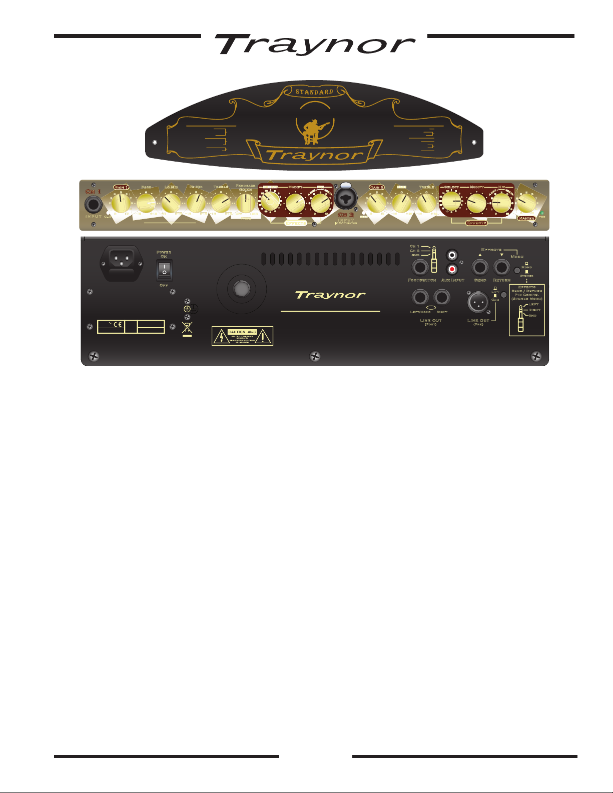
The Acoustic Master Standard
The Traynor Acoustic Master Standard is a 150-watt stereo acoustic guitar amplifier designed
to sound as natural as your guitar. The compact size and lightweight of the Acoustic Master
Standard make it easy to transport anywhere. The amplifier accepts the output from the active
or passive pickups of your acoustic guitar, a microphone, and even line-level signals. Other
features include 16 custom digital effects which can be user modified and independently
selected for each channel. Balanced line outs (pre and post effects), an effects loop, and a
sweepable notch filter make this amp perfect for stage use. The versatility and response of the
Acoustic Master Standard will make it a pleasure to play for years to come.
1. Power
The Blue LED, located next to the Master Volume, will illuminate when the unit is turned on.
The power switch is located at the back of the unit near the power receptacle / fuse holder.
2. Channel 1
Channel 1 has been voiced specifically for acoustic guitars. The input to Channel 1 is unbalanced
with an input impedance of 1 Mega-ohm and can accept either passive or active pick-ups (piezo/
coil). Controls include gain, bass, lo-mid, hi-mid and treble equalization, as well as a sweepable
notch filter. This filter eliminates most feedback generated by the guitar at high volumes.
3. Gain Control (Ch 1)
The Gain control is used to set the input level of your instrument. The clip LED can be used to
gauge input level to avoid audible clipping. If clipping does occur, lower the signal by turning
the volume down on your guitar or reducing the Gain control.
4. Tone Controls (Ch 1)
The Channel 1 tone controls help you access the wide range of sonic possibilities of the
Acoustic Master Standard. These controls DO NOT affect Channel 2. All tone controls can be
used to either boost or cut certain frequencies in your instrument’s signal. Use the Bass control
to reduce boominess or add low end thump. Change the mid frequency controls to add clarity
or reduce harshness. The High control can be adjusted to accentuate percussive sounds when
using a light pick or to attenuate the sound of your fingers moving across the strings.
1
Ch 1
Ch 2
Effects
Mode
Effects
Send / Return
Pin Config.
(Stereo Mode)
Acoustic Master
Standard
Send Re tu rn
Left/Mono Righ t
Line Out
(Post)
Line Out
(Pre)
Footswitch
Po wer
On
Off
Au x Inp ut
BAL
TYPE: YS1004 A-Z1150 / 1v0
230V
50Hz 0.8A
120VAC
60Hz 1.6A
CAUTION: REPLACE FUSE
WITH SAME TYPE AND RATING
ATTENTION: UTILISER UN FUSIBLE
DE RECHANGE DE MEME
TYPE ET CALIBRE
DESIGNED & MANUFACTURED BY
YORKVILLE SOUND • Toronto, CANADA
Gnd
Lift
St ere o
Mono
Left
Right
gnd
Ch 1
Ch 2
gnd
FUSE: T1,0A L
FUSE:
T1.25 ASlo blo
1
2
3
4
5
6
7
8
9
10
11
12
13
14
15
16
17
2738114561011
13
151716
14
12
9
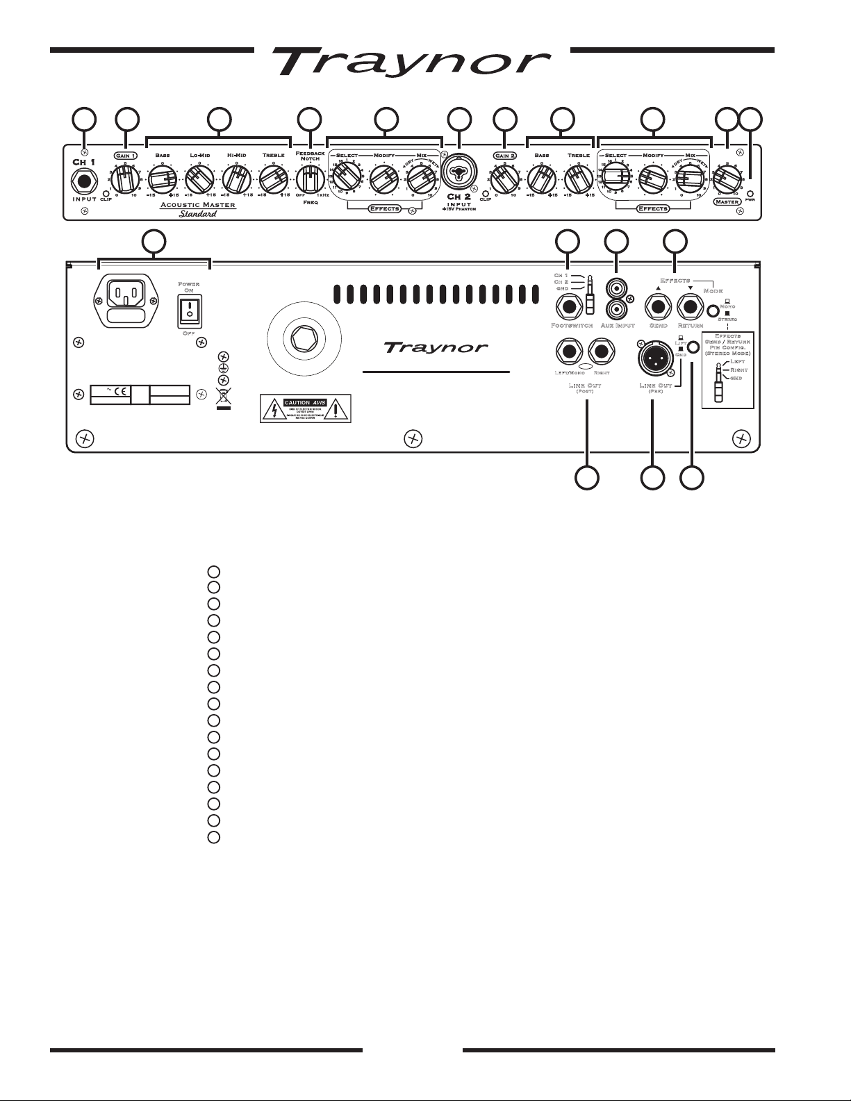
Power switch, Blue LED and AC power connector / fuse holder
Channel 1 Input – ¼-inch TRS phone jack
Channel 1 Gain control
Channel 1 Tone controls – Bass, Low-Mid, Hi-Mid and Treble
Channel 1 Feedback Filter control
Channel 1 Digital Effects controls.
Channel 2 Input – ¼-inch / XLR Combi-jack
Channel 2 Gain control
Channel 2 Tone controls – Bass and Treble
Channel 2 Digital Effects controls.
Master Volume control
Effects Loop – ¼-inch TRS phone jacks
AUX Input – RCA connectors
Footswitch – ¼-inch TRS phone jack
Stereo Line Out (post effects) – two ¼-inch TRS phone jacks (left and right)
Mono Line Out (pre effects) – XLR jack
Ground LIft switch
2
5. Notch Filter Control
Use the sweepable notch filter to eliminate feedback caused by the guitar being too close to the
amp at higher power. If feedback does occur, rotate the notch control slowly until the feedback is
eliminated. To bypass this filter, rotate it fully counter-clockwise to the off position. Please note that
if feedback occurs when you are in close proximity to the guitar amp, the notch filter may not help.
Therefore either reduce power or move the guitar farther away from the amplifier.
6. Digital Effects (Ch 1)
From lush reverb to a swirling rotary speaker simulator, the Acoustic Master Standard uses a
DSP (Digital Signal Processor) to create 16 custom Traynor effects. The Mix knob is used to
blend in the required amount of the original, clean signal. The Modify control is used to alter
the chosen effect. The parameter that can be changed is listed for each effect on the plate
found on the top of your amp. See the end of the manual for a description of each effect.
An optional footswitch can be used to bypass the Acoustic Master Standard’s built in
effects. Use a two-channel footswitch such as the Apex AFS2 to allow you to bypass
channel 1 and 2 independently.
7. Channel 2
This channel accepts line level signals from active acoustic guitars or other line level sources
via 1/4-inch cables. It also takes microphones through balanced XLR. Controls include
Gain, Bass and treble equalization. Channel 2 has a flat frequency response, making it ideal
for vocals, keyboards, and drum machines. The channel input is balanced but can also
accept unbalanced cables. To reduce noise, it is advised that you use balanced cables for
interconnection wherever possible.
In order to power condenser mics, a 15 volt phantom power is applied to devices connected
with an XLR cable. Using a correctly wired XLR cable, phantom power is effectively invisible
to balanced dynamic mics and will not cause any damage. Phantom power IS NOT applied to
the 1/4-inch portion of Channel 2.
8. Gain Control (Ch 2)
The Gain control is used to set the input level of your instrument. The clip LED can be used to
gauge input level to avoid audible clipping. If clipping does occur, lower the signal by turning
the volume down on your guitar or reducing the Gain control.
9. Tone Controls (Ch 2)
Channel 2 has a two band EQ for controlling your sound. Use the Bass and Treble controls to
boost or cut your signal to meet your needs.
10. Digital Effects (Ch 2)
Channel 2 has its own dedicated bank of 16 custom Traynor effects. Just as on Channel 1, the
Mix control blends between your dry and wet signals while the Modify control alters the nature
of the selected effect.
11. Master Volume
The master control is used to increase or decrease the overall output of the Acoustic Master
Standard. It has no effect on the line out signal level or the effects loop.
12. Effects Loop
Your Acoustic Master Standard has been equipped with an effects loop to allow you to add
off-board effects to your signal. The effects loop occurs just before the Master Volume but
after Channel 1 and 2 signals have been combined.
Connect a stereo 1/4-inch cable from the EFX Send jack on the back of the Acoustic Master
Standard to the input of your effects unit. The 1/4-inch cable carries stereo right on the ring,
stereo left on the tip and ground on the sleeve.
Connect the output of your effects unit to the EFX Return jack located on the rear of the
Acoustic Master Standard. The signal will go directly into the amp just before the Master
control. Using the same convention as the EFX Send jack, a stereo signal can be passed on a
stereo 1/4-inch cable. You can also supply the amp with a mono signal. Use the Stereo/Mono
switch next to the Effects Loop to select what type of signal you are using.
13. Aux In
The Aux In consists of a stereo RCA for use with line level devices like MP3 players, CD
players, etc. The signal is injected before the Master Volume control.
3
14. Footswitch Jack
An optional footswitch such as the dual switch, latching APEX AFS2 can be used to bypass
the built in effects for either channel, independently of each other.
15. Line Out - Post Effects ( 2 X 1/4-inch jacks, L&R)
The stereo line out jacks are located at the back of the unit and are post effect signals. They
are low noise, balanced TRS lines which can be used to connect to recording devices, mixers
or other amplifiers. The Master Volume control does not affect the signal however the Volume
and Tone controls of Channels 1 and 2 do.
16. Line Out - Pre Effects (XLR)
The Line Out is a balanced mono signal that combines Channel 1 and 2, but pre-effects
(i.e. this signal does not contain the Standard’s onboard effects). You can use this output to
directly connect to a mixer, or PA system. Please note that the Master control does not affect
the line out level, however the Volume and Tone controls of Channels 1 and 2 do.
17. Ground Lift Switch
The ground lift switch can be used for both pre and post EFX line outs to reduce any ground
hum. This switch is located at the back of the unit besides the XLR line out.
4
 Loading...