

Page 1

LIFT KIT ASSEMBLY MANUAL
ASSEMBLY INSTRUCTIONS
LONG ARM LIFT KIT
Page 2
Introduction
Thank you for purchasing the Traxxas TRX-4 Long Arm Lift Kit for added ground clearance and capability. This kit
includes everything you need to properly install a massive lift under your TRX-4 including long-arm links, longer
aluminum shocks, taller springs, extended driveshafts, and a revised front servo mount to maintain proper
steering geometry. If you have any questions or concerns about installing your kit, please contact our customer
support team for fast, friendly answers and solutions.
KIT CONTENTS
• Front Servo Mount
• Battery Plate Spacer (2)
• 3x20 BCS (4)
• Dierential T-Lock Cables
(168.9mm Front and 207.9mm Rear)
• Long Aluminum GTS Shocks (4)
• Shock Springs (4)
• Silicone Shock Oil
• Front Upper Suspension Link (assembled with
angled rod ends and hollow balls)
• Front Lower Suspension Link (assembled with
standard rod ends and hollow balls) (2)
• Rear Upper Suspension Links (assembled with
angled rod ends and hollow balls) (2)
• Rear Lower Suspension Links (assembled with
standard rod ends and hollow balls) (2)
• Standard Extended Rod Ends (assembled with
hollow balls) (4) (for 324mm wheelbase)
• Angled Extended Rod Ends (assembled with hollow
balls) (4) (for 324mm wheelbase)
• Short Female Half Shaft
• Medium Female Half Shaft (2)
• Long Female Half Shaft
• X-Long Female Half Shaft (2)
• 10-T Pinion Gear
• 3x3mm Set Screw
• Spare E-clips (2)
Note: Unless otherwise noted, retain and
reuse any hardware and parts from your
model that are not included with this kit.
2 • TRAXXAS
Page 3
Introduction
ITEMS YOU WILL NEED
• Hex driver • 4-way wrench
• Small at blade screwdriver
• Needle nose pliers
• Safety glasses
These items can be purchased from your hobby dealer.
If you have any questions, call the Traxxas Technical
Support Line toll-free at:
1-888-TRAXXAS (1-888-872-9927)*
Technical support is available Monday through
Friday from 8:30am to 9:00pm central time. Technical
assistance is also available at Traxxas.com. You may
also e-mail customer support with your question at
[email protected].
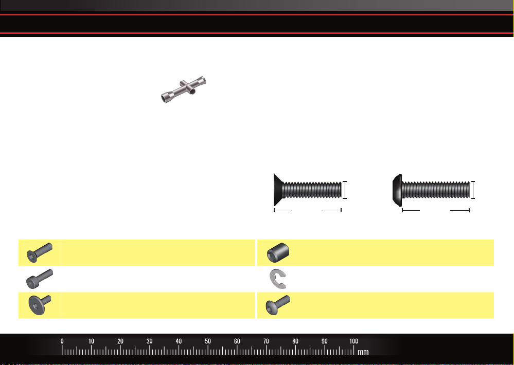
CCS Countersunk Cap Screw GS Set (Grub) Screw
CS Cap Screw E E-Clip
FCS Flathead Cap Screw BCS Buttonhead Cap Screw
*Toll-free support is available to U.S. residents only.
HARDWARE DESCRIPTIONS
The following chart is provided to help you identify the
many dierent sizes and types of hardware that are
used in the assembly of this lift kit. Note the dierence
between the length measurements of the roundhead
and countersunk screws. A ruler is provided at the
bottom of each page to measure the length of the
screws in millimeters.
3x12mm Countersunk Screw 3x12mm Buttonhead Screw
12mm
3mm
12mm
TRAXXAS • 3
3mm
Page 4
Suspension Link Guide
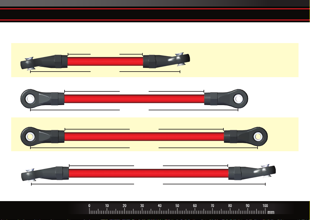
See the illustrations below for correct suspension link measurements for your model’s wheelbase.
SHORT WHEELBASE 312mm (12.3") (Traxxas Models 82046-4, 82016-4)
Front Upper Link
Front Lower Suspension Link
Rear Lower Link
42.65mm
85.44mm
79.47mm
118.47mm
90.45mm
129.45mm
Rear Upper Link
4 • TRAXXAS
90.45mm
133.24mm
(#8140R red version shown; suspension link color varies by kit part number)Note: Links are supplied assembled for the short (312mm) wheelbase.
Page 5
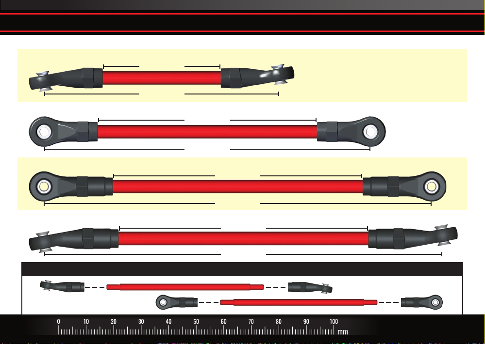
LONG WHEELBASE 324mm (12.7") (Traxxas Models 82056-4, 82066-4)
Front Upper Link
Front Lower Suspension Link
Rear Lower Link*
42.65mm
85.44mm
79.47mm
118.47mm
90.45mm
140.95mm
Suspension Link Guide
Rear Upper Link*
90.45mm
144.74mm
*Note: Rear links require installation of included extended rod ends for 324mm long wheelbase use.
TRAXXAS • 5
Page 6
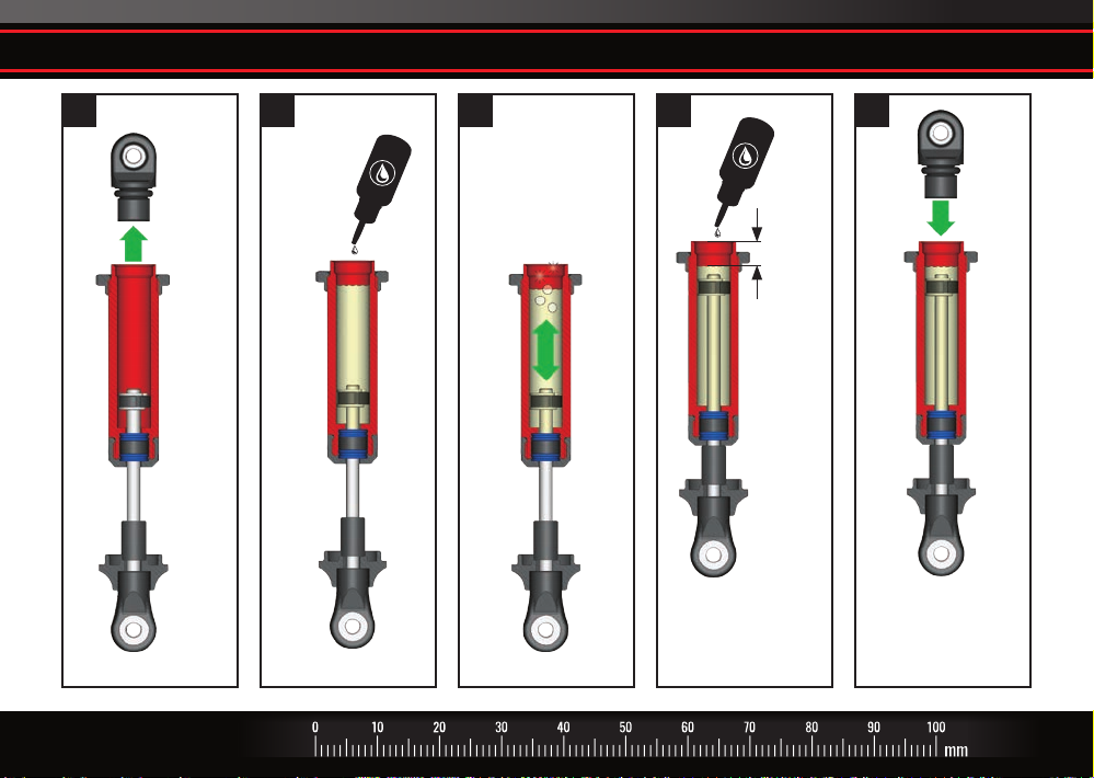
A. Assemble GTS Shocks
1 2 3 4 5
Fill with
shock oil
Unscrew
cap
Slowly move
piston to remove
excess air
6.7mm
(.26")
(#8140R red version shown)
6 • TRAXXAS
Keep lower spring
retainer installed.
Add oil to reach
the proper level.
Note: Shaft
should be fully
compressed when
cap is installed.
Page 7
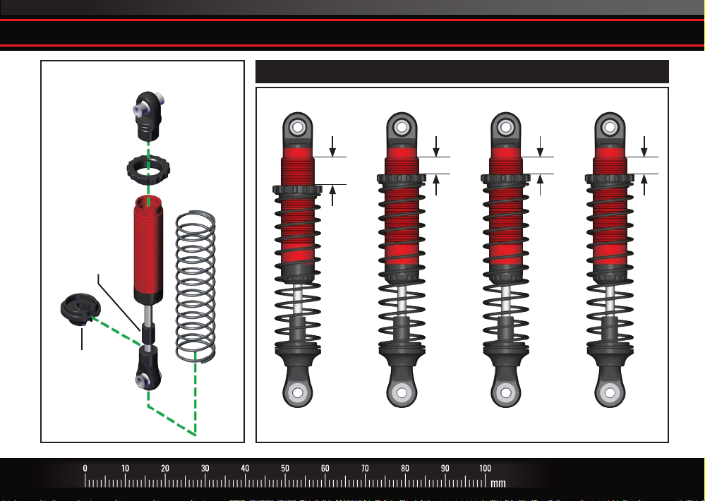
A. Assemble GTS Shocks
GTS Shock Exploded View
Upper Spring
Retainer
Bump
Stop
Lower Spring
Retainer
Shock Cap
Shock
Spring
Exercise shock to make sure it compresses fully. If it does not, it is overlled.
Suggested Spring Preload Settings (May require ne tuning when body is installed)
9mm
Left Front Shock
Assembled
Right Front Shock
Assembled
5mm 5mm 5mm
Left Rear Shock
Assembled
Right Rear Shock
Assembled
TRAXXAS • 7
Page 8
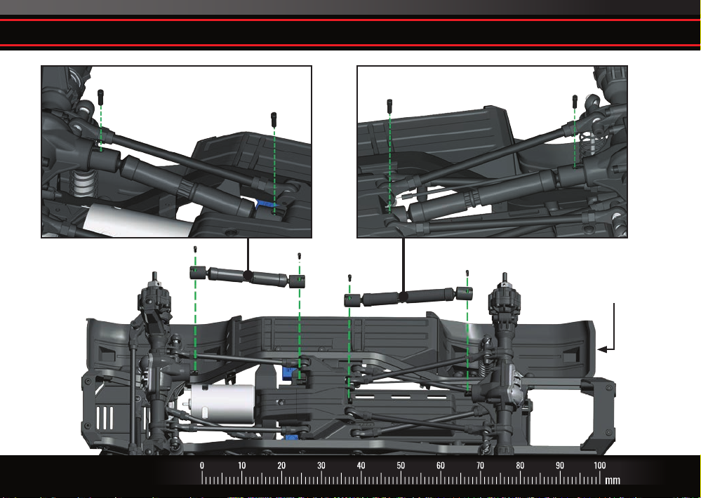
B. Remove the front and rear center driveshaft assembly
8 • TRAXXAS
3x10mm
Screw Pin
Front driveshaft removal
3x10mm
Screw Pin
Rear driveshaft removal
3x10mm
Screw Pin
3x10mm
Screw Pin
Note: Some TRX-4 models are not equipped
with chassis mounted wheel wells; however,
the installation instructions are the same.
Page 9
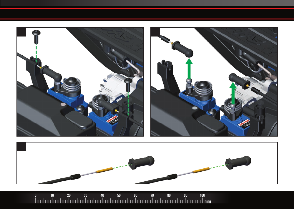
C. Remove the T-Lock cables from the shift servos
1
3
2.6x8mm
BCS
2.6x8mm
BCS
Unscrew and remove the ball cups from the T-Lock cables. Retain the ball cups.
2
TRAXXAS • 9
Page 10
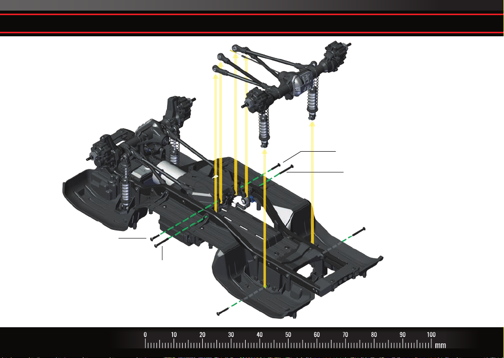
D. Remove the rear axle assembly from the chassis
3x15mm BCS
(Rear Lower Link)
3x25mm BCS
(Rear Upper Link)
3x23mm BCS
(Rear Shock)
3x15mm BCS
(Rear Lower Link)
3x25mm BCS
(Rear Upper Link)
3x23mm BCS
(Rear Shock)
10 • TRAXXAS
Page 11
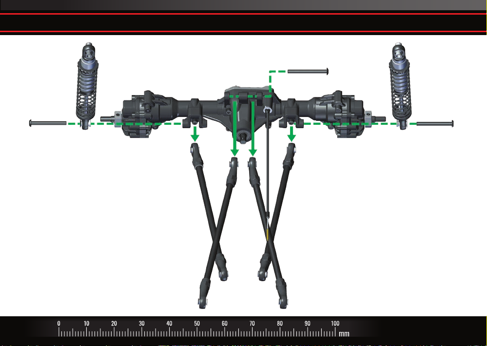
E. Remove the shocks and rear suspension links from the axle assembly
Right Rear
Shock Assembly
3x27mm BCS
(Shocks and Rear
Lower Link)
Rear Lower
Suspension Link
Rear Upper
Suspension Link
3x30mm BCS
(Rear Upper Links)
Rear Lower
Suspension Link
Rear Upper
Suspension Link
Left Rear
Shock Assembly
3x27mm BCS
(Shocks and Rear
Lower Link)
TRAXXAS • 11
Page 12
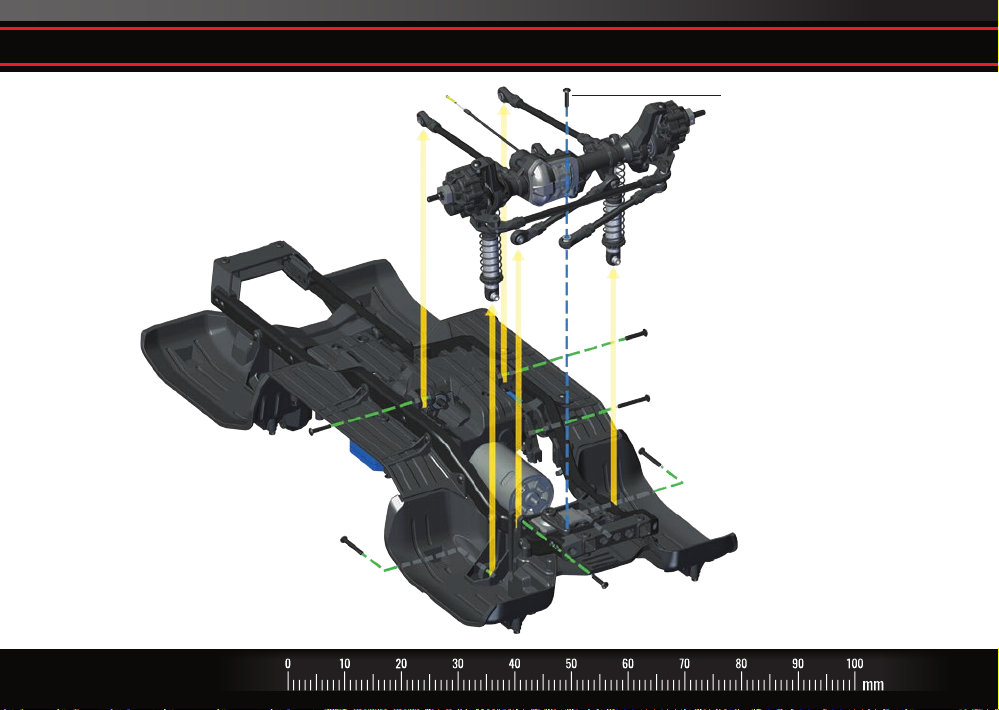
F. Remove the front axle assembly from the chassis
3x15mm BCS
(Steering Link)
3x15mm BCS
(Front Lower Link)
3x23mm BCS
(Front Upper Link)
12 • TRAXXAS
3x15mm BCS
(Front Lower Link)
3x23mm BCS
(Front Shock)
3x23mm BCS
(Front Shock)
3x15mm BCS
(Front Panhard Bar)
Page 13
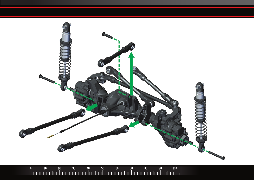
G. Remove the shocks and front suspension links from the axle assembly
3x15mm
BCS
Left Front
Shock Assembly
3x27mm
BCS
Front Lower
Suspension Links
Front Upper
Suspension Link
Right Front
Shock Assembly
3x27mm
BCS
TRAXXAS • 13
Page 14
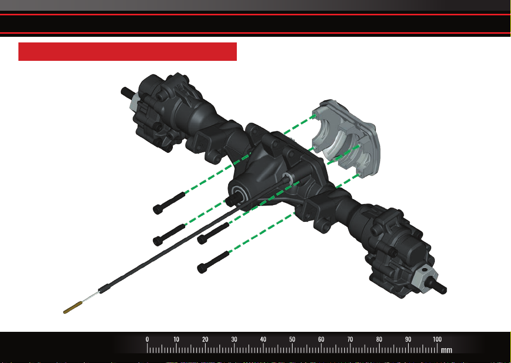
H. Remove the dierential cover from the front and rear axle assemblies
Rear Axle Assembly shown. Repeat for Front Axle Assembly.
2.5x16mm
CS
2.5x16mm
CS
14 • TRAXXAS
Page 15
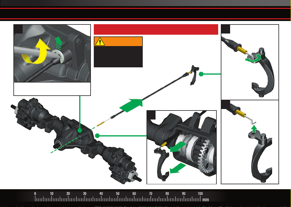
I. Remove the locking fork from the locking slider
1
Use a small at blade screwdriver to
remove E-clip from axle housing.
Rear Axle Assembly shown. Repeat for Front Axle Assembly.
WARNING
Safety glasses are
recommended to
prevent eye injury.
2
3
Remove
T-Lock Cable
4
TRAXXAS • 15
Page 16
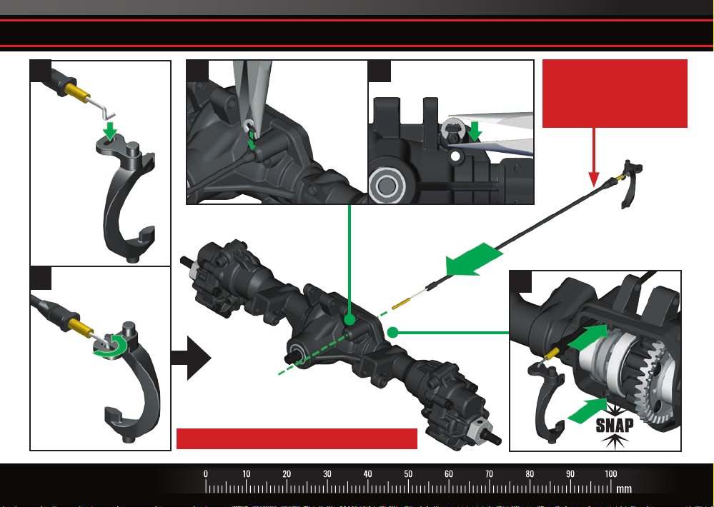
J. Install the new T-Lock cable in the axle assemblies
1
Assemble locking fork
and kit locking cable
2
16 • TRAXXAS
Use needle nose pliers
to set E-clip between
locking cable and
axle housing.
Rear Axle Assembly shown. Repeat for Front Axle Assembly.
Use needle nose pliers to press
54
E-clip onto locking cable.
Install the longer 207.9mm
cable in the Rear Axle Assembly
and the shorter 168.9mm
cable in the Front Axle Assembly.
3
Page 17
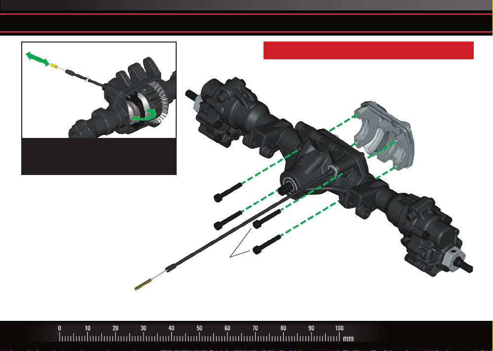
K. Install the dierential cover on the axle assemblies
Rear Axle Assembly shown. Repeat for Front Axle Assembly.
Note: Move the end of the locking cable in
and out to verify the locking fork moves
back and forth on its pivot.
2.5x16mm
CS
2.5x16mm
CS
TRAXXAS • 17
Page 18
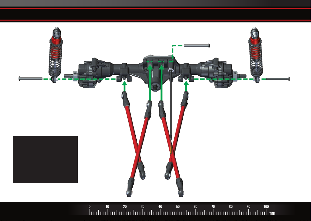
L. Install the new lift kit suspension links and GTS shocks on the rear axle assembly
Right Rear
Shock Assembly
3x27mm BCS
(Shocks and Rear
Lower Link)
See the Suspension Link
Guide on pages 4 and 5
for correct suspension
link measurements for
your model’s wheelbase.
(#8140R red version shown)
18 • TRAXXAS
Rear Lower
Suspension Link
Rear Upper
Suspension Link
3x30mm BCS
(Rear Upper Links)
Rear Lower
Suspension Link
Rear Upper
Suspension Link
Left Rear
Shock Assembly
3x27mm BCS
(Shocks and Rear
Lower Link)
Page 19
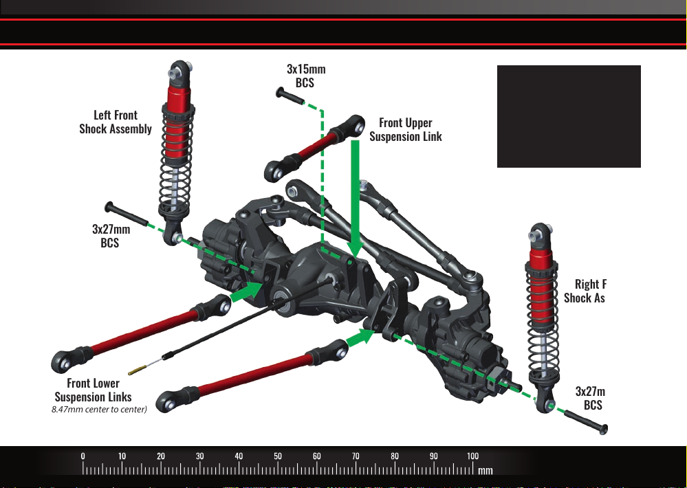
M. Install the new lift kit suspension links and GTS shocks on the front axle assembly
Left Front
Shock Assembly
3x27mm
BCS
Front Lower
Suspension Links
(118.47mm center to center)
(#8140R red version shown)
3x15mm
BCS
Front Upper
Suspension Link
See the Suspension Link
Guide on pages 4 and 5
for correct suspension
link measurements for
your model’s wheelbase.
Right Front
Shock Assembly
3x27mm
BCS
TRAXXAS • 19
Page 20
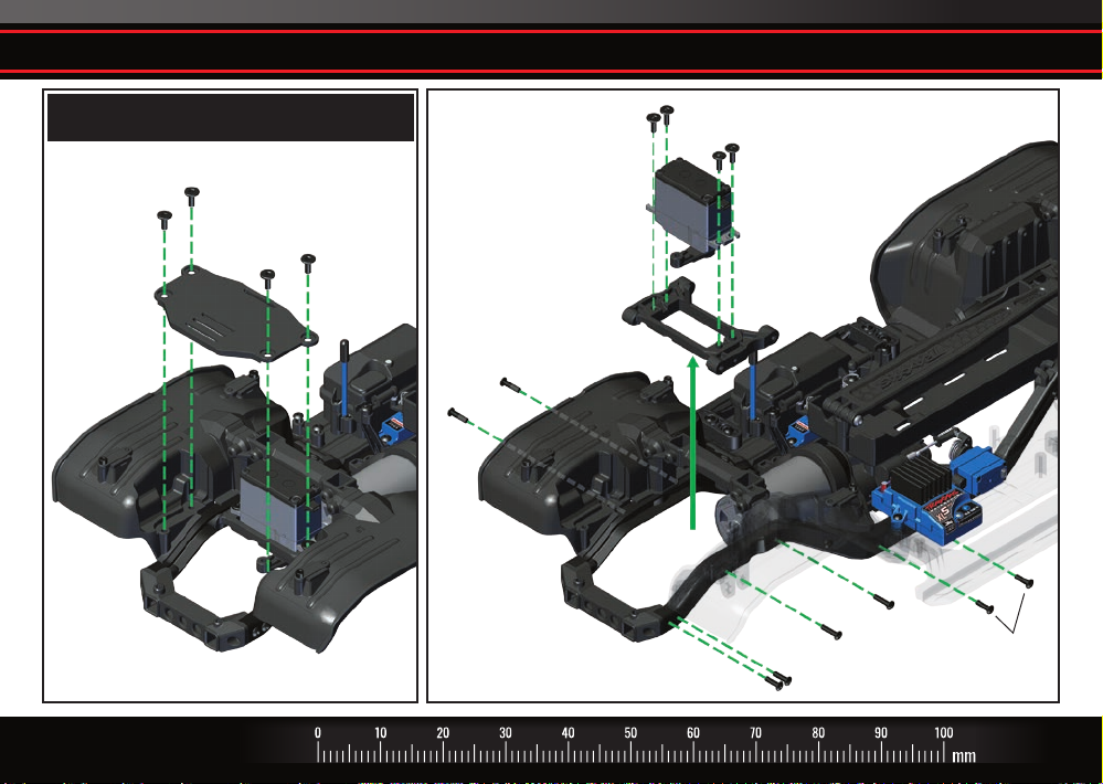
N. Remove the battery plate and existing steering servo mount.
Skip this step if your vehicle is not
equipped with a front battery plate.
3x8mm
FCS
3x8mm
FCS
Front Battery
Plate
3x12mm
BCS
3x10mm
FCS
Steering Servo
Mount
3x10mm
FCS
3x12mm
BCS
3x10mm BCS
3x10mm
BCS
20 • TRAXXAS
Page 21
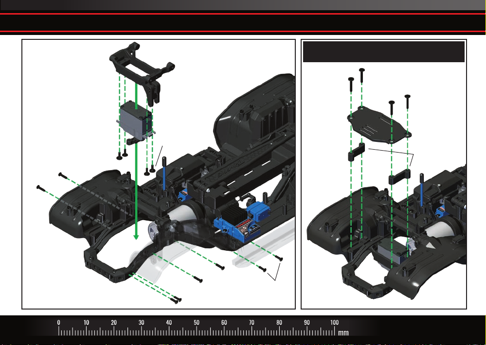
O. Install new lift kit steering servo mount and battery plate spacers
3x12mm
BCS
3x10mm
FCS
Lift Kit Steering
Servo Mount
3x10mm
FCS
3x12mm
BCS
3x10mm BCS
3x10mm
BCS
Skip this step if your vehicle is not
equipped with a front battery plate.
3x20mm
FCS
Front Battery
Plate
3x20mm
FCS
Lift Kit Battery
Plate Spacers
TRAXXAS • 21
Page 22
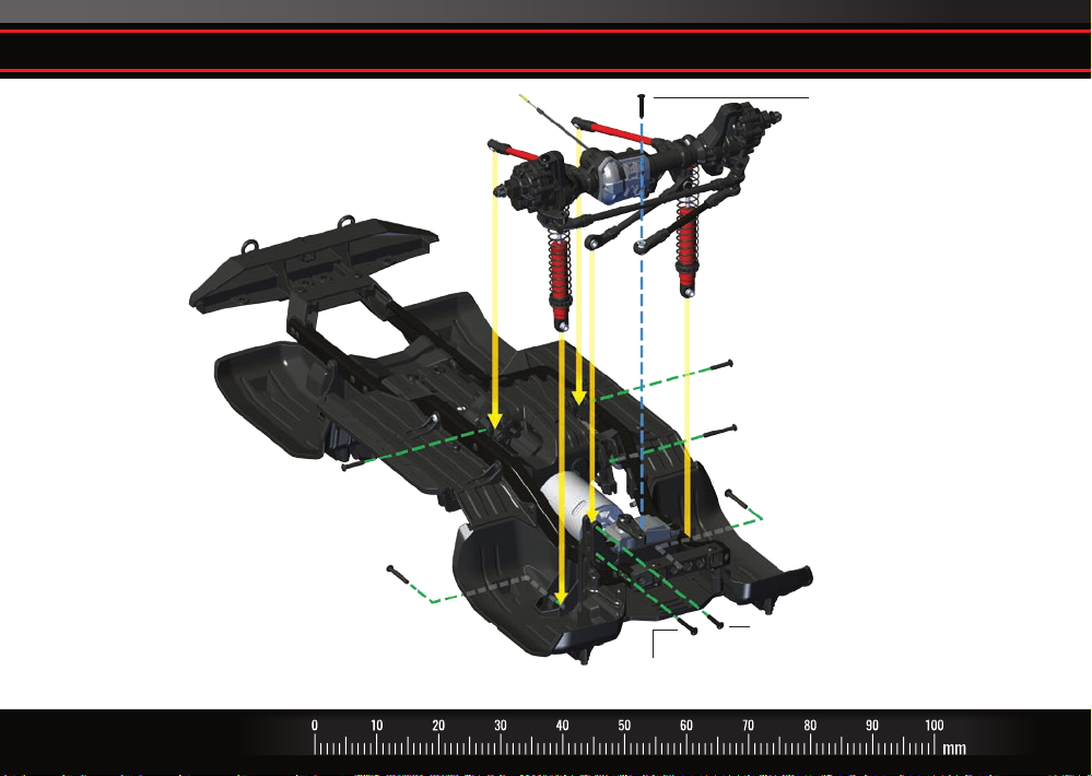
P. Reattach front axle assembly to chassis
3x15mm BCS
(Steering Link)
3x15mm BCS
(Front Lower Link)
3x23mm BCS
(Front Upper Link)
3x15mm BCS
(Front Lower Link)
3x23mm BCS
(Front Shock)
(#8140R red version shown)
Also available:
#8146R red steering link, drag link, and panhard bar set
#8146X blue steering link, drag link, and panhard bar set
3x23mm BCS
22 • TRAXXAS
(Front Shock)
3x23mm BCS
(Front Shock)
3x15mm BCS
(Front Panhard Bar)
3x20mm BCS
(Servo Mount)
Page 23
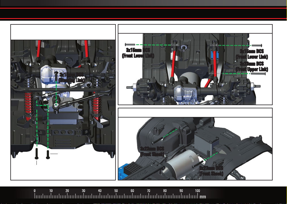
P. Reattach front axle assembly to chassis
Install front panhard bar to chassis
and steering link to steering servo
3x15mm BCS
(Steering Link)
3x15mm BCS
(Front Panhard Bar)
3x20mm BCS
(Servo Mount)
(#8140R red version shown)
Install upper and lower suspension links to chassis
3x15mm BCS
(Front Lower Link)
Install front shocks to fenders from top of chassis
3x23mm BCS
(Front Shock)
3x15mm BCS
(Front Lower Link)
3x23mm BCS
(Front Upper Link)
3x23mm BCS
(Front Shock)
TRAXXAS • 23
Page 24
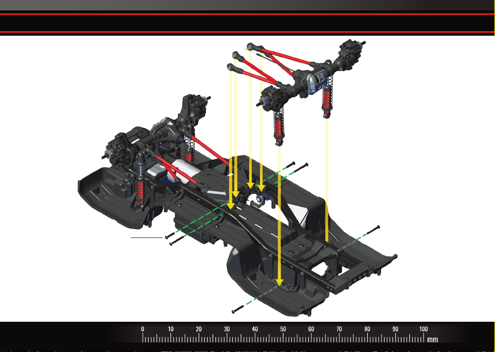
Q. Reattach rear axle assembly to chassis
3x15mm BCS
(Rear Lower Link)
(#8140R red version shown)
3x25mm BCS
(Rear Upper Link)
3x23mm BCS
(Rear Shock)
3x15mm BCS
(Rear Lower Link)
3x25mm BCS
(Rear Upper Link)
3x23mm BCS
(Rear Shock)
24 • TRAXXAS
Page 25
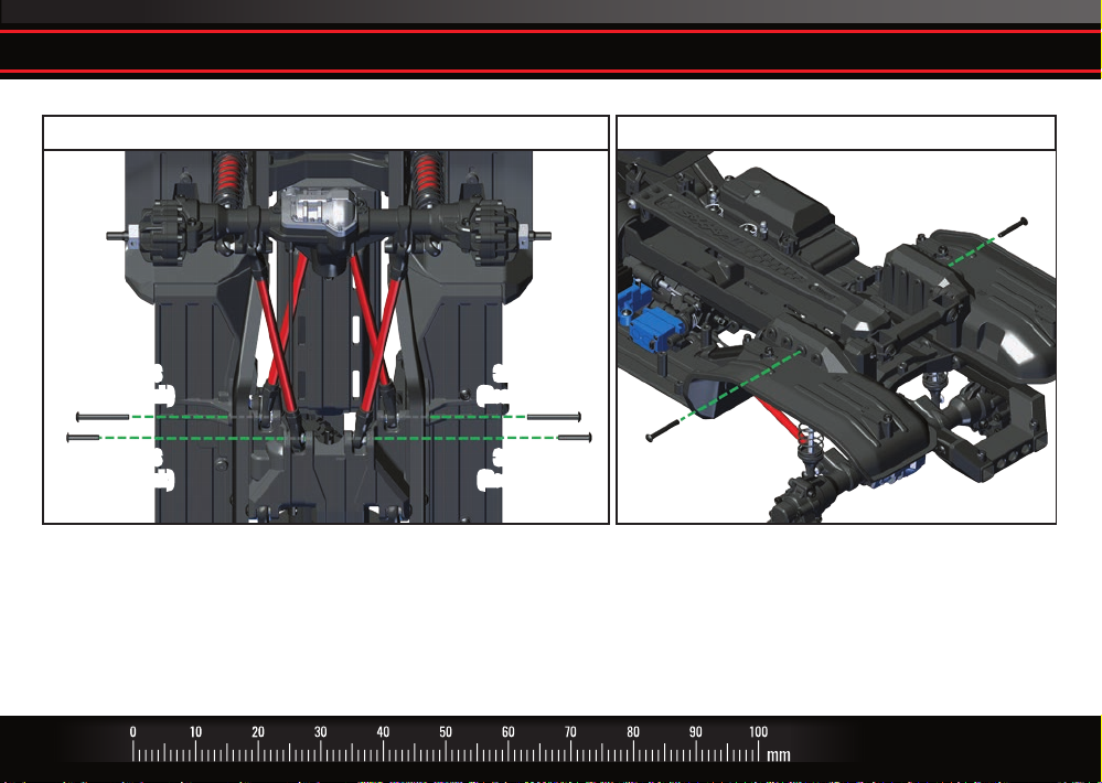
Q. Reattach rear axle assembly to chassis
Install upper and lower suspension links to chassis Install rear shocks to fenders from top of chassis*
3x23mm BCS
(Rear Shock)
3x25mm BCS
(Rear Upper Link)
3x15mm BCS
(Rear Lower Link)
(#8140R red version shown) *Short (312mm) wheelbase shown; shock mounting position will vary depending on wheelbase conguration.
3x25mm BCS
(Rear Upper Link)
3x15mm BCS
(Rear Lower Link)
3x23mm BCS
(Rear Shock)
TRAXXAS • 25
Page 26
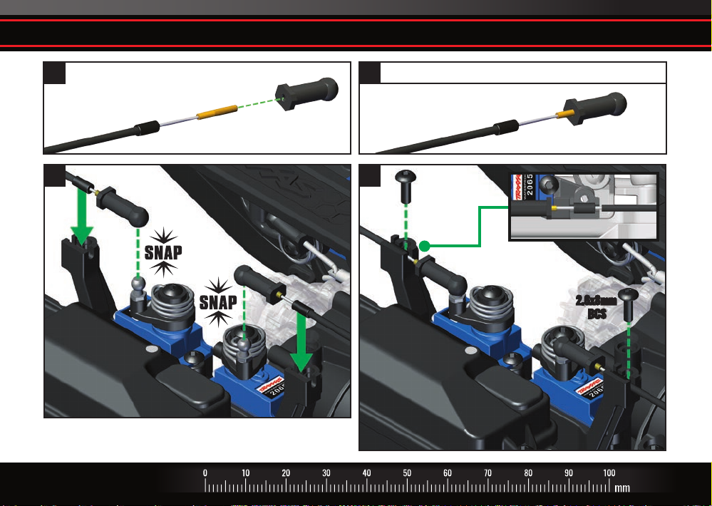
R. Reconnect T-Lock cables to shift servos
1 2
Dierential
Cable
It is okay to slightly rock horn to align ball cup.
Do not turn servo shaft by hand or you could damage the servo.
26 • TRAXXAS
Axle Ball Cup
Screw ball cup on until all threads are hidden
43
2.6x8mm
BCS
2.6x8mm
BCS
Page 27
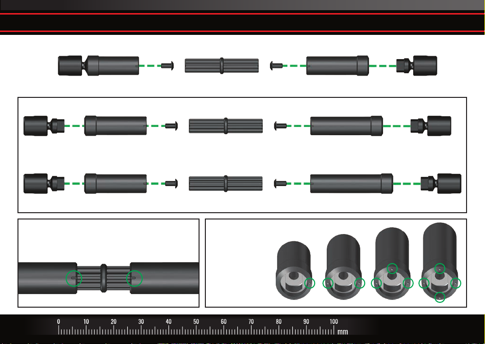
S. Remove stock half shafts and assemble new driveshafts
FRONT DRIVESHAFT
SHORT
Replace the stock half shafts with the supplied half shafts.
3x6mm
BCS
3x6mm
BCS
REAR DRIVESHAFT - SHORT WHEELBASE 312mm (Traxxas Models 82046-4, 82016-4)
MEDIUM
3x6mm
BCS
3x6mm
BCS
REAR DRIVESHAFT - LONG WHEELBASE 324mm (Traxxas Models 82056-4, 82066-4)
MEDIUM
3x6mm
BCS
Note: Orient and assemble the center drive shafts
as shown to correctly phase the output drives.
Note: Use the molded
indicators to identify
the length of the
half shaft.
3x6mm
BCS
SHORT
MEDIUM
LONG
MEDIUM
XL
LONG XL
TRAXXAS • 27
Page 28
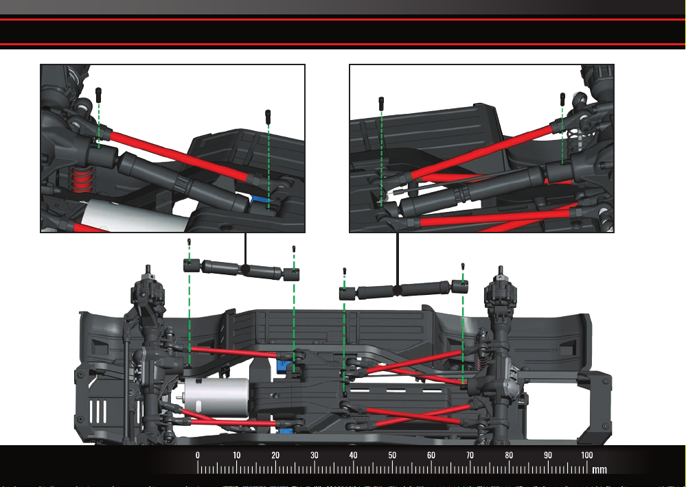
T. Install new front and rear center driveshaft assemblies
3x10mm
Screw Pin
(#8140R red version shown)
28 • TRAXXAS
Front driveshaft install
3x10mm
Screw Pin
Rear driveshaft install
3x10mm
Screw Pin
3x10mm
Screw Pin
Page 29
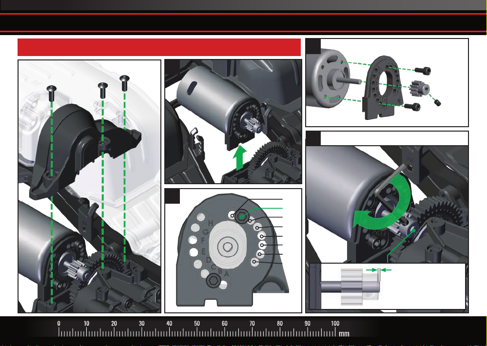
U. Remove 11-T pinion gear and install new 10-T pinion gear on motor shaft
10-T pinion gear maintains original performance with larger 2.2” tires
Gearing access
3x8mm BCS
3x8mm BCS
Upper
Gear Cover
1
3
2
3x8mm CS
3x4
GS
3x8mm CS
Mesh gear teeth, and then tighten set screw
4
A
B
C
D
E
F
G
H
Pinion gear should be
1-1.5mm from end of
motor shaft
TRAXXAS • 29
Page 30
Notes
30 • TRAXXAS
Page 31
Notes
TRAXXAS • 31
Page 32

180427 KC2561-R00
PART #8140, 8140R, 8140X
6250 TRAXXAS WAY, McKINNEY, TEXAS 75070
1-888-TRAXXAS
 Loading...