

Page 1
Visitez Traxxas.com/manuals pour télécharger
les instructions dans votre langue.
Visite la página Traxxas.com/manuals para
descargar el instrucciones en su idioma.
Auf Traxxas.com/manuals, können Sie
anleitung in Ihrer Sprache downloaden.
1/16 Summit LED Light Kit Instructions
Covers Part(s) #7285A, 7286A, 7287, 7288
Note: Ensure vehicle battery is unplugged before beginning installation. Retain and reuse all parts and fasteners (unless otherwise noted).
Your motor and electronic speed control (ESC) may differ slightly from the one shown in the illustrations.
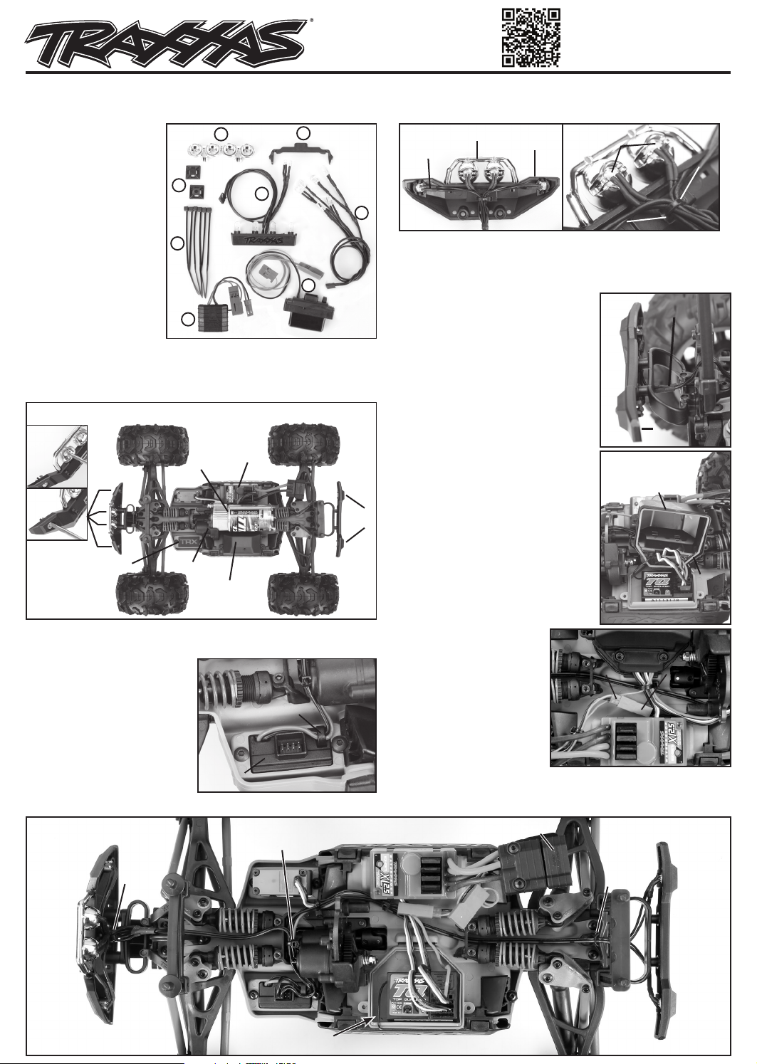
Kit Contents:
5
6
1. LED lighting module
(included with part(s)
#7285A and 7286A only)
2. Power tap
3. LED harness (chassis)
8
4
3
4. LED harness (body)
5. Body light bar
6. Rear light bar
7. Zip ties (6)
8. Zip tie mounts (2)
7
1
4. Continue to route the LED harness down the center of the chassis as
shown in (D). Reinstall the front bumper; then, plug the LED harness
connector into the LED lighting module. Route the module wires and
the LED harness around the transmission and secure them with a zip
tie (trim excess) (D).
2
Tools Needed:
• 2.5mm hex driver • 2.0mm hex driver • 1.5mm hex driver • Body reamer
• Wire cutter (to trim zip tie excess)
Tip: Sort the hardware by assembly as you remove them so you can easily
locate the correct hardware during reinstallation (A).
Remove These Parts to Allow Installation of the
LED Light Kit
Front
bumper
Motor
ESC
Rear
bumper
5. Fully loosen the two rear shock mount
screws, raise the rear shock mount
slightly, and route the 2-LED end of
the harness under the shock mount
(between the shocks), as shown. (D)
Tighten the rear shock mount screws;
then, continue routing the LED harness
toward the rear bumper.
CAUTION: Do not pinch the wiring
between the shock mount and the chassis.
6. Snap the LEDs into the rear bumper.
Route the wires against the rear bumper,
then, reinstall the rear bumper (E). Plug
the LED harness connector into the LED
Blank
LEDs
lighting module.
7. Thread the red wire from the LED
lighting module through the opening
in the receiver box cover and plug the
Servo guard / cover plate
(retain hardware)
Gear cover
Receiver box cover
and wire clamp
connector into any available channel in
the receiver box (D, F).
Note: If you install the included power
tap, the red female connector from the
power tap can be used to connect the
Chassis installation
1. Remove the parts shown in Fig. A.
2. Install the LED lighting module
and route the wires through the
loop guide (B).
3. Snap the 4-LED end of the LED
harness (chassis) into the front
light bar and front bumper.
Route the wires against the
front bumper and secure the
wires to the bumper loop with
a zip tie (trim excess) (C).
temperature/voltage sensor
(part #6523, sold separately)
to the ESC.*
8. Reinstall the ESC, the receiver
box cover, the wire clamp,
the motor, and the gear
cover. Plug the black wire
(red female connector) from
the LED lighting module
into the black wire (red male
connector) from the ESC (G).
Note: Ensure that the blue o-ring is properly seated in the groove around the
receiver box cover base. Check for proper adjustment of the gear mesh. Refer to
the vehicle Owner’s Manual for detailed instructions.
High-Current Connector
Zip tie
Zip tie
Receiver box
(Receiver box cover and
wire clamp removed from the wiring lay-out for clarity)
Zip tie
Page 2
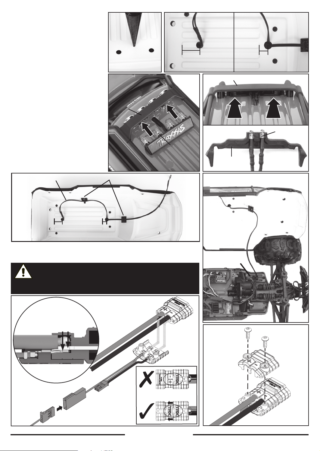
Body installation
1. Use a body reamer or a drill to cut two 7mm
wide holes in the roof of the vehicle body,
as shown (H, I).
Note: It is important to cut the holes in the
appropriate locations or the LEDs will not mount
correctly (I).
2. Replace the front blank light bar on the top
of the vehicle with the supplied body light
bar.
3. Thread both sections of the LED harness
(body) down through the front drilled
hole. Snap the LED lights into the body
light bar (J).
4. Thread the 2-LED end of the harness up
through the rear drilled hole. Snap the
LED lights into the rear light bar and
position it under the Exo-Cage (K).
5. Pull any excess length of the harness to the
underside of the vehicle body and secure
with the supplied zip ties and mounts.
Position the zip tie mounts as shown (L).
Note: Use alcohol to clean the underside of the
vehicle body before attaching the zip tie mounts.
6. Plug the wiring harness into the LED
lighting module and reinstall the body (M).
7. The lights will turn on when the ESC is
turned on.
LED harness Zip tie/mount
Rear Inside Roof Front Inside Roof
11/16” (17mm) 1/4” (6mm)
Exo-cage
TOP VIEW
Rear light bar
LED lights
11/16” (17mm)
Installation of the power tap
Note: If the wiring from your speed control is not equipped with the 2-pin male connector (black wire
with red connector), you must install the included power tap on the High-Current Connector.
1/4” (6mm)
CAUTION: RISK OF DAMAGE TO
Note the polarity and wire color on the
pre-installed wires on the power tap. Ensure the polarity is correct during
installation on the High-Current Connector: red (+) (positive), black (-) (negative).
Temperature/Voltage
Sensor (part #6523,
sold separately)*
ACCESSORIES!
During installation, be sure that
the terminals of the High-Current
Connector and the power tap
make full contact.
ESC Wiring
Power Tap
High-Current
Connector
ESC Wiring
ESC
Power Tap
Wire colors mismatched
LED
Lighting
Module
2.6x8mm BCS
ESC Power
Tap Cover
ESC Wiring
*TQi Radio System required for functionality. Visit Traxxas.com for more information.
TRAXXAS.com
Traxxas, 6250 Traxxas Way, McKinney, TX 75070,
Phone: 972-549-3000, Fax: 972-549-3011, e-mail: [email protected]
HKC20056-R02 201026
 Loading...