

Page 1
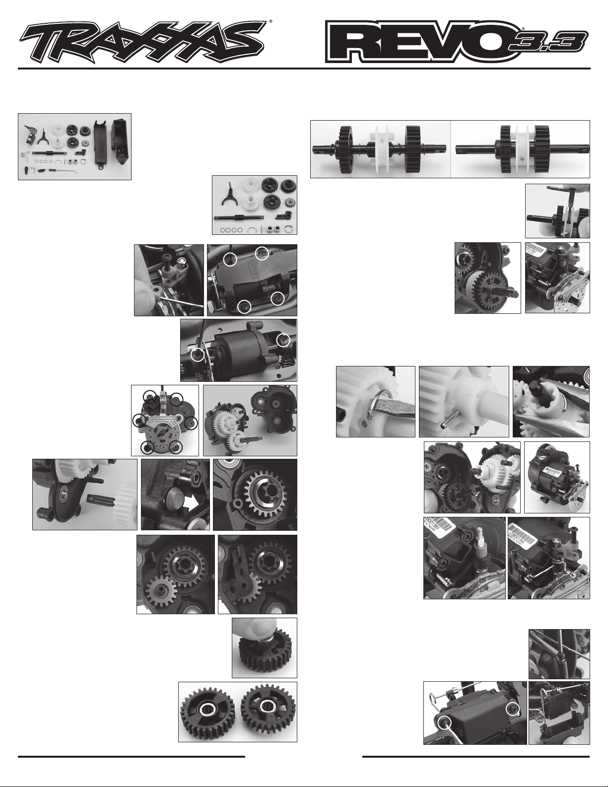
Revo 3.3 Forward/Reverse Kit Instructions
Important Note: This kit does NOT include the OptiDrive system. The truck must
come to a complete stop before shifting gears. See below for shifting instructions.
Tools Needed:
• 2.0mm hex wrench
• 2.5mm hex wrench
• Needle-nose pliers
• Small flat-blade screwdriver
• 5.5mm nut driver
Covers Part #5395X
orientation (1M). Note: The FWD/REV gears must be installed onto the output
shaft with the integral markings of the roller bearings facing toward the center
of the shaft.
1M
Forward/Reverse Gear Installation:
1. Remove the air filter from the carburetor, and
then remove the brake rod from the brake lever
by loosening the 3x12mm button-head screw far
enough to pull the rod guide from the lever. The
brake linkage does not need to be removed from
the throttle servo (1A).
2. Flip the truck over and
remove the four 4x10mm
button-head screws that
attach the center skid plate
to the chassis (1B).
3. Next, remove the two screw
pins from the front and rear
output yokes of the transmission, and then
slide the yokes off of the shaft. This will
release the transmission from the top of
the chassis (1C).
4. Remove the six 3x12 countersunk screws
from the transmission (1D) and separate
the transmission halves (1E).
5. Remove the forward-only
gear shaft assembly from
the transmission (1F), and
then pull the blue rubber
plug (1G) from the front
transmission half.
1F
6. Next, place the 22T steel
primary gear into the front
transmission half, followed by
the disk spring (see photo 1H
for correct orientation).
7. Slide the steel reverse idler
gear (w/bearing) over the
molded plastic post next to
the steel primary gear (1I),
followed by the plastic idler shaft support (1J).
8. Locate the two black forward and reverse gears along
with the two metal needle roller bearings. Press a roller
bearing assembly into each gear with the integral marking
facing out and away from the gears (1K). Be sure to press
the bearing assemblies all the way into each gear until it
bottoms out inside the gear (1L).
9. Locate the FWD/REV output shaft, dog
slider, four 6x8 PTFE washers, and the two
black FWD/REV gears with installed roller
bearing assemblies. Install these items
onto the output shaft using the photo and
exploded view for correct sequence and
1A 1B
1C
1D
1G
1I 1J
1L
Traxxas, 1100 Klein Road, Plano, TX 75074,
Parts needed for these steps
1E
1H
1K
TRAXXAS.com
Phone: 972-265-8000, Fax: 972-265-8011, e-mail: [email protected]
10. Next, locate the shift fork and shaft assembly. Position the
shift fork inside and around the groove of the plastic dog
slider on the output shaft (1N). Note: The shift fork shaft
must face toward the black reverse gear (thin gear).
11. Insert the entire assembly into the front transmission half.
The output shaft is located through the 6x12mm bearing
at the bottom of the case, and the
shift fork shaft should slide through
the same hole where the blue rubber
plug was removed (1O). Remember to
position the front brake disc between
the brake calipers before sliding the
output shaft all the way into the
transmission case (1P).
12. Remove the forward-only primary gear from the two-speed shaft by removing
the primary pin retainer clip from the gear to access the cross pin (1Q). Push the
pin out of the gear and slide the gear off of the shaft (1R). Replace the gear with
the included forward/reverse primary gear in the same orientation and secure
the gear with the pin and retaining clip (1S).
1O 1P
1Q 1R
13. Next, carefully join the
two transmission halves
together (1T) and secure
them with the six 3x12mm
countersunk screws (1U).
14. Remove the 3mm locknut
from the brake lever and
slide the brake lever off of
the brake cam shaft (1V).
Install the torsion spring
onto the brake cam shaft
(see image 1W for correct
orientation), followed by
the brake lever. Secure the
assembly with the 3mm
locknut. Insert the bent end
of the spring into the hole
located in the shift fork.
15. Install the transmission back onto the chassis in reverse order of how it was removed.
Left-side radio box installation
1. Remove the 2.5x6mm cap-head screw from the throttle
servo mount to release the throttle return spring (2A).
2. Remove the two 4x10mm button-head screws from the
bottom of the throttle servo mount (2B), and then remove
the four 3x10mm flat-head
screws securing the throttle
servo. Lift the throttle
servo out of the mount and
remove the mount from the
chassis (2C).
1
1
2B
T
V
1N
1S
1
U
1
W
2A
2C
KC1153-R01 121218
Page 2
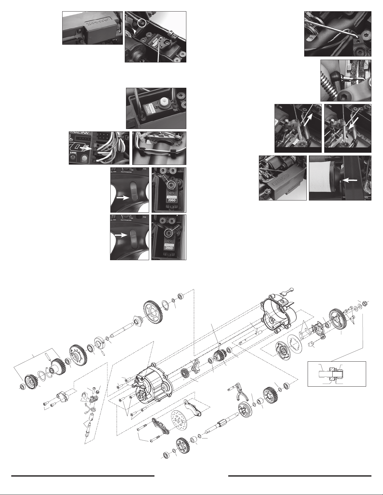
3. Place the included
left-side radio
2D 2E
box into the same
location and
secure it to the
chassis with the
same two 4x10mm button-head screws (2D).
4. Place the throttle servo into the radio box and
secure it with the same four 3x10 flat-head
screws. Next, secure the throttle return spring to the radio box with the
included 3x6mm button-head screw (2E).
Channel 3 (CH3) / Shift Servo Installation
1. Locate the #2060 shift servo and the two 3x6
3A
button-head screws. Install the servo into the
left-side radio box between the two plastic
molded posts in front of the throttle servo (see
photo 3A for correct orientation).
2. Open the right side receiver box, and then insert
the shift servo plug into the CH3-port in the
receiver (3B). Close
the receiver box and
3B
3C
route the shift servo
wire through the two
plastic wire clips in
the chassis (3C).
3. Turn on the transmitter and the ON/
OFF switch on the Revo. Make sure that
3D
3E
the red forward/reverse switch on the
transmitter is positioned in the down
(forward) position (3D). Locate the
included shift servo horn and install the
servo horn onto the output shaft (see
image 3E for correct orientation).
Note: The servo output shaft is splined to
match the inside of the servo horn. Make
3F 3G
sure that the grooves are lined up before
applying pressure to the servo horn.
4. Next, press up on the red forward/
reverse switch (3F). The shift servo horn
should swing clockwise approximately
90-degrees to the right (away from the
transmission)(3G). Important: If the shift servo horn swings in the opposite
direction than described above, then switch the CH3 servo reverse switch on
the transmitter to the opposite position, and then repeat Step 3.
5. Shift the red shift button on the transmitter
back to the down position, and then turn off
3H
the transmitter and the ON/OFF switch on
the Revo. Secure the servo horn to the shift
servo with an included 3x6mm button-head
screw. Locate the shift linkage wire with the
installed plastic ball cup at one end. Insert the
bare bent end through the outside hole of
the servo horn, and then push down (see image 3H for
correct orientation). The wire should pivot freely.
3I
6. Connect the ball cup to the ball end of the torsion
spring located on the brake cam (3I). This should press
the shift fork shaft into the transmission (forward).
7. Turn on the transmitter and Revo. Press up on the red
shift button. The shift servo should pull the shift fork
shaft out of the transmission
(reverse) (3J). Pressing the
3J
3K
switch back down should push
the shift fork shaft back into the
transmission (forward) (3K).
8. Turn the transmitter and the
Revo off. Install the left side
radio box cover onto the radio
box and secure it with the
90-degree body clip (3L).
Install the air filter onto
Switch Up / Reverse Switch Down / Forward
3L
3M
the carburetor, and then
place the intake neck
of the air filter between
the molded legs on
the radio box top (3M).
This completes the
installation.
Forward/Reverse Shifting Tips
• This kit does not include the OptiDrive module (part #5398) or sensor (part
#5397). The truck must come to a complete stop before shifting.
• After the truck has come to a complete stop, push the red shift button up to
actuate reverse or press down to actuate forward.
• After shifting, allow the truck to roll slightly to ensure positive engagement of the
transmission. Once the truck lurches forward or back, it is then okay to apply throttle.
CAUTION: Do not switch gears at high speeds. This can cause serious damage to
the transmission gears.
5384 (wide)
5385 opt. (std.)
5383 opt. (close)
5396X
5117
6x12 BB
*
5116
5x11 BB
5397
(2.5x6 CS 3215)
*Apply a light coating of automotive wheel bearing grease to these gears.
5368
5388
2578
3x12 BCS
5392
5390
5119
10x15 BB
3.0 NL
2745
5390
6x8x.5 PTW
5390
2552
3x12 CCS
Traxxas, 1100 Klein Road, Plano, TX 75074,
5393
5393
Primary shaft
2552
3x12 CCS
4978
3x21 Shoulder BCS
5391R
5352X
5351
5117
6x12 BB
5395
(1-888-872-9927) (U.S. residents only)
5386
5365
5117
6x12 BB
5393
5x8x.5 PTW
5391R
6x8x.5 PTW
5393
3982
5116
5x11 BB
5377
*
5395
5364
5364X
5385
M3 x 13.75
(screw pin)
5116
5x11 BB
5377
(Includes bearing)
5365
3982
6x8x.5 PTW
5121
6x10 NRB
(text on bearing
towards shaft center)
5116
5x11 BB
5384 (wide)
5385 opt. (std.)
5383 opt. (close)
5389X
5369 (output shaft)
5391R
5352
5366
3982
6x8x.5 PTW
3982
6x8x.5 PTW
5121
6x10 NRB
(text on bearing
5395
towards shaft center)
If you have questions or need technical assistance, call Traxxas at
1-888-TRAXXAS
TRAXXAS.com
Phone: 972-265-8000, Fax: 972-265-8011, e-mail: [email protected]
5352X
5x11 BB
535X2
5366
5116
5x11 BB
5352X
(5.0 NL 4147)
5116
3x6 CS
3954 38-T
3953 opt. 36-T
5351
3955 opt. 40-T
5352X
(5.0 NL 4147)
Correct orientation on shaft
5352X
5352X
2554
 Loading...