

Butler S2
Setup Manual

Published by/Herausgegeben von
Traxon Technologies Europe GmbH
An OSRAM Business
Karl Schurz-Strasse 38
Paderborn, Germany
Setup Manual Butler S2
Edition 18.01.13
©2012, Traxon Technologies Europe GmbH
All rights reserved/Alle Rechte vorbehalten
Comments and corrections:/Kommentare und Korrekturen an:
documentation@traxontechnologies.com

Table of Contents
English ......................................................................5
Safety instructions ....................................................................................6
Delivery content ........................................................................................6
Optional accessories ...........................................................................6
Overview ...................................................................................................7
Transport .................................................................................................. 7
Inspect the delivery content ..................................................................... 7
Connectors and interfaces ....................................................................... 8
Cuelist displays .................................................................................... 9
System messages .............................................................................10
Power supply ..........................................................................................10
e:net ........................................................................................................10
DMX ........................................................................................................11
DMX pin assignment ..........................................................................11
System button ........................................................................................ 11
During system boot ...........................................................................11
During normal operation in online mode ............................................. 11
In standalone mode and during normal operation ..............................12
In standalone mode and in an error condition ....................................12
microSD card .........................................................................................12
Status LEDs ............................................................................................12
Using the standalone web interface ...................................................13
Online configuration ........................................................................... 15
Basic Butler S2 settings ..................................................................... 15
Network parameters .......................................................................... 17
Setting Device Properties ...................................................................20

Firmware update ....................................................................................22
Technical Data ........................................................................................23
General data ...................................................................................... 23
Interfaces ...........................................................................................23
Deutsch ..................................................................24
Sicherheitshinweise ................................................................................25
Lieferumfang ..........................................................................................25
Optionales Zubehör ...........................................................................25
Übersicht ................................................................................................ 26
Transport ................................................................................................ 26
Überprüfen des Lieferumfanges .............................................................26
Anschlüsse und Schnittstellen ...............................................................27
Cuelist-Anzeige ..................................................................................28
System-Meldungen............................................................................ 29
Stromversorgung ....................................................................................29
e:net ........................................................................................................29
DMX ........................................................................................................30
DMX-Anschlussbelegung ...................................................................30
System-Taster ........................................................................................ 30
Während der Boot-Phase .................................................................. 30
Während des Normalbetriebes im Online-Modus ............................... 30
Während des Normalbetriebes im Standalone-Modus .......................31
Während eines Fehlerzustandes ......................................................... 31
microSDHC-Karte ..................................................................................31
Status-LEDs ...........................................................................................31
Standalone-Webinterface...................................................................32
Online-Konfiguration ..........................................................................34
Butler S2 Grundeinstellungen ............................................................. 34
Netzwerk-Parameter ..........................................................................36

Setup Manual - Butler S2
Setzen der Geräteeigenschaften ........................................................ 39
Firmware-Update ...................................................................................41
Technische Daten ................................................................................... 42
Allgemein ........................................................................................... 42
Schnittstellen ..................................................................................... 42
Appendix ................................................................43
Dimensions/Abmessungen.....................................................................44
Notes/Notizen ......................................................................................... 45
5

Setup Manual - Butler S2
English
6
Setup Manual - Butler S2
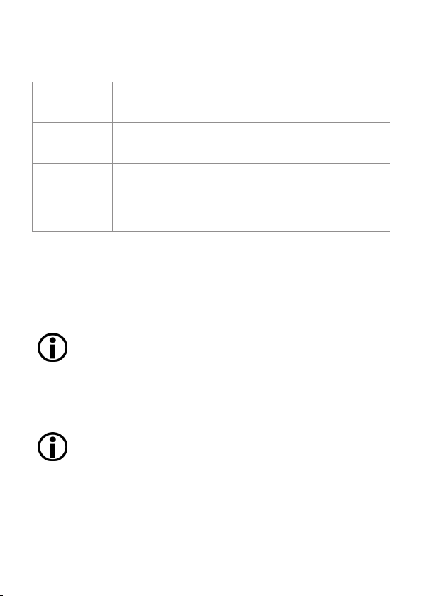
Safety instructions
Only use the device in compliance with the environmental conditions
specified in the technical data. Otherwise the unit will be damaged.
i
To prevent the device from overheating, only operate it in well-ventilated environment. Otherwise the unit may overheat and fail.
i
Actions described in this manual may only be performed with special
care by skilled personnel. Incorrect handling may damage the unit
i
Repairs may only be carried out by authorized, specially trained personnel to ensure reliability. When in doubt, contact e:cue service.
i
Delivery content
• Butler S2 device EN.BU.0000001
• 2-pin screw terminal AC.BU.0000003
• microSDHC card for show storage AC.BU.0000002
• Setup Manual English/German
Optional accessories
• Butler S2 accessory pack AC.PS.1003401
(12 V DC/12 W plug power supply, connector)
• Butler S2 Garage AC.BG.0000001
(for up to 12 Butler S2 incl. power supply, 3U)
• RJ45-to-XLR5 adapter cable AC.BU.0000010
7

Setup Manual - Butler S2
Overview
The e:cue Butler S2 is a DMX/RDM engine that can be used either in standalone
mode to replay and loop previously uploaded lighting shows, or as a DMX output
device controlled by another e:cue server with an e:net connection. It is programmed using a PC or the e:cue Lighting Control Engine running the e:cue
software suite. One compact Butler controls up to 1024 DMX channels in two
DMX universes. Up to 99 cuelists for shows in standalone mode are stored on a
micro SD card. The DMX channel control can be increased to 16,384 channels by
clustering more Butler S2s. The Butler is powered by an external power supply with
12 - 24 V DC or via 48 V DC PoE (Power over Ethernet). A 7-segment LED is used
for message and status display.
Transport
Only transport the Butler S2 in its original packaging. This protects the device from
damage. Only unpack the at its installation location. To protect the device against
condensation water, unpack it and wait until all moisture remaining in the Butler S2
has evaporated. Condensation can occur when the device is moved from a cold to
a warm location.
Inspect the delivery content
Unpack the Butler S2 and inspect all parts for completeness. Keep the packaging
for use in case of further transport. If there is apparent damage to the device or
parts are missing from the delivery scope, please contact e:cue service.
8
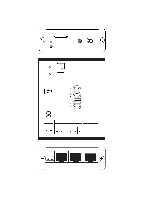
Connectors and interfaces
Setup Manual - Butler S2
microSD slot
ACT (green)
LINK (orange)
7-segment LED display
Select button
e:net activity
microSD
Activity
Link
DMX/RDM Output Engine
Butler S2
EN.BU.0000001
Made in Italy
www.traxontechnologies.com
PWR
In
Power DMX 2 DMX 1 e:net
DMX/RDM
DMX2 DMX1
1 2 3 1 2 3
IEEE 802.3af
Power input: 12 ... 24 V DC
Max. current: 250 mA
e:net
PoE
9
Setup Manual - Butler S2
Control/interface Function
e:net activity Two LEDs, showing physical link to a server
microSD slot Keeps an microSD card for show and data
Select button For cuelist control and system operations
7-segment LED display Show system messages and current cuelist
Power Power supply 12 … 24 V DC
DMX1 DMX output universe #1/RDM universe #1
DMX2 DMX output universe #2/RDM universe #2
e:net e:net/Ethernet connection
system (Link) and data exchange (Activity)
storage
status
Cuelist displays
Online mode
o
Standalone mode
When in normal operation mode the display consecutively shows the current
sync state, the output mode and the number of cuelists that are played at the
moment. The status is displayed as SYN - MODE - CL - [pause]
SYN The sync mode, either the Butler S2 is master or slave.
A
b
MODE This show the output mode of the Butler S2
d
CL Cuelist information. 0 … 8 for the number of simultaneously playing
4
A clockwise rotating circle show connection to a system and the
Programmer of the Lighting Application Suite. The Butler S2 is now in
online mode to be congued or to receive cuelist uploads.
»A« This Butler S2 is a master.
»b« This Butler S2 runs in slave mode.
»d« The Butler outputs DMX.
cuelists. 0 means no cuelist available.
The number of cuelists is displayed as a single digit.
10
Setup Manual - Butler S2
System messages
L O A d
C r d
S E r
r E S
»LOAd« Butler S2 is in bootloader mode. This display may result
from an incomplete firmware update or when the system button
is pressed while powering up the Butler S2.
»Crd« Card error, the microSD card is missing, a le is corrupt
or a read error occured. Press the button, if the error reappears rewrite the card.
»SEr« Serial number error. The reading of the serial number
failed. Repower system. If the error reappears contact your
e:cue service.
The Butler S2 executes a soft reset after the System button was
pressed for at least four seconds.
Power supply
The Butler S2 can be powered by an external AC/DC power supply or via Powerover-Ethernet (PoE). The power supply must deliver a supply current of 250 mA.
Only use the e:cue power supply. The PoE supply voltage is 48 V DC. Power-overDMX is not supported.
When using Power-over-Ethernet do not connect any power supply
physically to the DC Input of the Butler S2. Otherwise the power feed
from Ethernet will not be recognized.
e:net
Use standard CAT5 (RJ45) network cabling for e:net.
Please remember that e:net requires an isolated network segment
and cannot operate properly when using e.g. internet or video/audio
streaming in the same network simultaneously.
11
Setup Manual - Butler S2
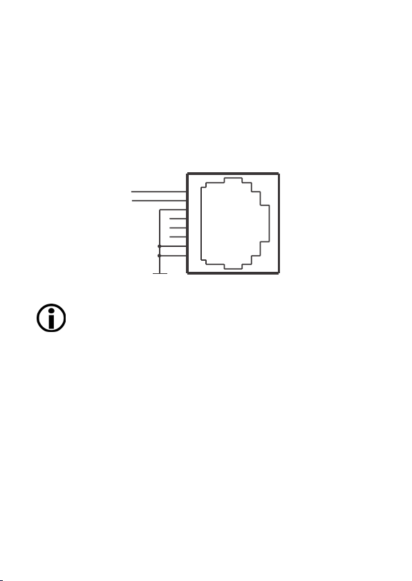
DMX
The DMX output is taken from the RJ45 connectors labeled „DMX1“ and „DMX2“.
To connect DMX using a XLR5 type plug, please use the adaptor cable, item
number 40005, available as e:cue accessory or contact your nearest e:cue distributor for a suitable adaptor cable.
DMX pin assignment for plug
J1
DMX1–
DMX1+
Do never use RJ45 cross-cables (TX and RX lines exchanged) on the
DMX interfaces. This can destroy the DMX interface of the Butler S2!
GND
1
2
3
4
5
6
7
8
RJ45-2X4
System button
During system boot
• Keeping the system button pressed while powering up the Butler S2 starts the
bootloader mode and displays L O A d , no further loading happens.
• Keeping the system button pressed for three seconds, the Butler S2 displays
d E F . If the system button is released now no changes are made.
• If you keep the system button pressed for additional three seconds all parameters including the IP address will be reset to factory settings. The IP address is
now 192.168.123.1 again.
During normal operation in online mode
• When in online mode, connected to the Programmer, a short press marks this
12

Setup Manual - Butler S2
Butler S2 in the Network tab with a small asterisks. This helps to identify the
Butler S2 in a Butler Garage or in a huge configuration. Additionally the assigned
Action is triggered.
In standalone mode and during normal operation
• When pressed for a short time (less than six seconds) the Butler S2 executes the
Action assigned to the system button. See the Lighting Application Suite System
Manual for a detailed list of assignable Actions.
• Keeping the button pressed for more than six seconds a fast blinking r E S gets
displayed. If the button is released now a soft reset is executed and the Butler S2
returns to normal operation.
• Keeping the button pressed for more than 12 seconds a fast blinking d E F is
displayed. Releasing the button now resets the configuration of the Butler S2 to
factory settings. This includes the IP, which is then 192.168.123.1 again.
• If you keep the button pressed for more than 18 seconds no changes are made.
In standalone mode and in an error condition
• A short press acknowledges the error and restarts the system.
microSD card
The Butler S2 comes with a microSDHC card. The Butler S2 cannot operate if no
microSD card is present. As a typical show file and configuration files do not take
up more than a few Megabytes space, it is generally not necessary to replace the
provided microSD card with a bigger one. If the microSD card has been removed
during operation and is restored, the show may be continued by pressing the button on the device – otherwise you need to reboot.
Do not remove the SD card while the Butler S2 is in operation!
13
Setup Manual - Butler S2
LAN
Ethernet switch
Power supply
Butler S2
RJ45
RJ45
12 ... 24 V DC
Status LEDs
e:net Link OFF: no Ethernet link
e:net Activity OFF: no data transfer
System configuration
For a complete overview of other functions like clustering and assignments of Actions and programming of shows see the System Manual for the Lighting Application Suite, available for download from www.traxontechnologies.com for free.
The Butler S2 can either be configured in standalone mode without the Lighting
Application Suite and only with a web browser and a PC, or it can be setup in online
mode with the Lighting Application Suite. Configuration in standalone mode is most
recommended when the Butler S2 has his factory settings.
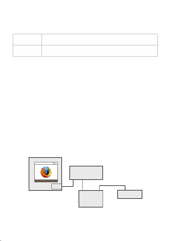
Using the standalone web interface
You can set the network parameters of the Butler S2 without any other system using a standard web browser on any PC or PC-like system.
Connect the Butler S2 with power and via a standard LAN patch cable over an
Ethernet switch to the server (LCE or PC). If you want to connect the Butler S2
without Ethernet switch to the server use a so called cross cable, as not all Ethernet
interfaces support automatic RX/TX detection.
ON: link established
ON: Ethernet data exchange in progress
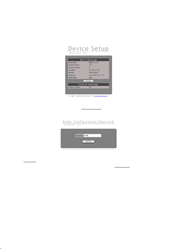
Start the web browser and enter the IP address of the Butler S2 in the address
14
Setup Manual - Butler S2
field of the browser, in factory state 192.168.123.1 (if the Butler was configured
differently before and you do not know the IP address, perform a »Reset to factory
settings«). You can now see the current settings and parameters.
To change the configuration, click the Congure button and enter the password.
The default password is “ecue”, it can be changed during configuration.
Click Enter and the main configuration dialogue gets displayed. Change the
parameters (explained in the following chapter) and click Submit.
15

Setup Manual - Butler S2
Online configuration
If not already available, download the e:cue Lighting Application Suite (LAS), for this
visit www.traxontechnologies.com and follow the download link from the LAS page.
Install the e:cue Lighting Application Suite on a server system like a notebook or a
PC system.
The Butler S2 requires e:cue LAS Version 5.6 or higher.
Connect the Butler S2 with power and via a standard LAN patch cable over an
Ethernet switch to the server (LCE or PC). If you want to connect the Butler S2
without Ethernet switch to the server use a so called cross cable, as not all Ethernet
interfaces support automatic RX/TX detection.
16

LAS server
Setup Manual - Butler S2
Ethernet switch
LAN
RJ45
RJ45
Butler S2
12 ... 24 V DC
Power supply
Start the Programmer from the Lighting Application Suite. In the Application
Options in the main icon menu use the Advanced settings tab. Adjust the net-
work card and IP address for the adapter that will be used to connect the server to
the network switch and the Butler S2.
Basic Butler S2 settings
Select the Network tab from the upper left window to see network configuration
and settings. Here you should see all devices in the network segment including the
Butler S2. If you need more details see the System Manual for the Lighting Application Suite, also available for download from the Traxon Technologies website.
To set the basic configuration the Butler must not be used in the Programmer. Click
on the Butler S2 line. This opens the dialogue for all basic settings including the
network parameters.
17

Setup Manual - Butler S2
Set the necessary parameters for the Butler S2. The factory settings for the IP
address is 192.168.123.1, be sure that no other device in the network uses this IP
address.
When setting up more then one Butler S2 with factory settings, connect only one to the network, set a new IP address, then connect and
configure the next Butler S2.
Network parameters
Device Basics
Device Name The device will be displayed with this name in the e:cue
IP address The IP address of the device (default: 192.168.123.1)
Subnet Mask The netmask of the device (Default: 255.255.255.0)
Gateway address The default gateway of the device (Default: no gateway)
MAC address The physical address of the device (read only)
18
programmer.

Setup Manual - Butler S2
Versions
Hardware Build Version The hardware version (read only).
Software Build Version The software version (read only).
Cluster Mode
Cluster ID Generated ID of the cluster for master/slave mode.
Cluster Size Number of engines in this cluster.
Device Mode Master or Slave n/m (n of m).
Advanced Setup
Lock Settings Checkmark, set by default, avoids changes for DMX
and RDM by chance.
BRK Length Break signal length in µs for the DMX protocol.
MAB Length Mark after break length in µs for the DMX protocol.
BRK Length RDM Break length in µs for the RDM protocol.
MAB Length RDM Mark after break length in µs for the RDM protocol.
RDM Switch Time The RDM Tx to Rx length in in µs.
BRK Length Break length for e:pix protocol (not used).
MAB Length Mark after break length for e:pix protocol (not used).
Do not modify the Advanced Settings, if you are not fully aware of the results.
Close the Network Configuration Dialogue, the changes will be transferred to the
Butler S2. You can now integrate the Butler S2 to the Programmer for DMX output
or show upload.
Execute the Device Manager dialogue of the Programmer by clicking the smartphone symbol in the top menu.
19

Setup Manual - Butler S2
The Device Manager becomes active. Use the Network Wizard to find all new
devices in the network, click the hat icon in the upper menu.
The Device Manager Wizard will find the new Butler S2 in the network. Deselect the
option to check for e:bus devices, as the Butler S2 has no e:bus interface.
20

Setup Manual - Butler S2
Click OK to connect the Butler S2 to the Programmer as DMX output device. The
Device Manager now shows the Butler S2 in his device overview.
After a short time the status will change from Warming up to Online.
21

Setup Manual - Butler S2
Setting Device Properties
The Butler S2 can now be configured for use as an DMX output device. Doubleclick on the Butler S2 in the Device Manager’s overview. This opens up another
dialog where the application options (device properties) for the Butler S2 can be set.
Alternatively move the mouse cursor over the device name, press the right mouse
button and select Properties.
Set the proper application options for the Butler S2, click OK to apply the changes.
22

Setup Manual - Butler S2
Enable driver Set the checkmark to make the device online, remove
to set it to ofine mode = standalone mode.
Private logbook Checkmark to use a separate logbook in the Pro-
grammer. If unset, the Butler S2 messages appear in
the main log.
Alias name An arbitrary alias name to identify the Butler S2 in the
Programmer.
Comment A comment, e. g. the location or the function.
Generic
IP address The selected IP address.
DMX Output
Output Universe DMX1 The DMX universe ID in the Programmer, for which
port DMX1 of the Butler S2 is used.
Output Univers DMX2 The DMX universe ID in the Programmer, for which
port DMX2 of the Butler S2 is used
RDM
Enable for DMX1 Enable RDM for DMX1 of the Butler S2.
Enable for DMX2 Enable RDM for DMX2 of the Butler S2.
Export
First cuelist number The rst cuelist index which is sent to the Butler S2
when exporting shows.
Cuelist count The number of cuelists, that get exported.
Export Group UID The UID for the master/slave group on export.
Action Pad Not used at the moment.
The Butler S2 is now configured and can be used as DMX output engine or as
standalone engine after uploading shows.
For details about RDM and the RDM browser in the Lighting Application Suite
please see the System Manual for the LAS, available for free download from www.
traxontechnologies.com.
23

Firmware update
To update the firmware on the Butler S2 first download the latest firmware release
from the Traxon Technologies website see the Butler S2 page for details. Download
the firmware file and save it in a local directory on your server.
Start the Patchelor from the e:cue Lighting Application Suite. Every engine available
in the network gets displayed, also the Butler S2 to update. Be sure that the checkmark in front of the Butler S2 is unset.
• Select the Butler S2 with a click, press the right mouse button and select Up-
date Firmware.
• Select the file with the new firmware (*.bxt) in the upcoming dialog.
• After the download is complete the Butler S2 will restart with the new firmware.
The new firmware is available now.
If the update fails, the Butler will start with a message L O A d . Power down the
Butler S2 and repower keeping the system button pressed. Retry to download the
new firmware.

Setup Manual - Butler S2
Technical Data
General data
Dimensions
(W x H x D)
Weight 125 g
Power 12 … 24 VDC via ext. PSU
Rated current max. 250 mA
Power consumption 2.7 W (incl. DMX termination)
Operating/storage temp. 0 … 40 °C/32 … 104 °F
Operating/storage humidity 0 … 80% non-condensing
Protection class IP20
Electrical safety SELV
Materials Aluminium, plexi glass, steel
Mounting Desktop or in Butler Garage
Certification CE
Interfaces
Operator display 7-segment LED
Control keys 1 x Push button
e:net/Ethernet 1 x RJ45, 10/100 MBit, PoE enabled
Supply power 2 x Screw terminals, cable width 0.25 … 1 mm²
DMX/RDM 2 x RJ45, USITT DMX512-A/RDM E1.20
Conforms to UL Std. UL 60950-1
Cert. to CSA Std. C22.2 No. 60950-1
71.5 x 24 x 85 mm/
2.7 x 0.9 x 3.6 inch (w/o power plug)
48 V DC via PoE
2 x e:net status LEDs
Electrically isolated up to 1000 V
25

Setup Manual - Butler S2
Deutsch
26

Setup Manual - Butler S2
Sicherheitshinweise
Verwenden Sie da Gerät nur unter den angegebenen Umgebungsbedingungen, anderenfalls kann das Gerät beschädigt werden.
i
Bestandteile des Gerätes werden im Betrieb heiß. Vor Demontage
oder Wartung das Gerät abkühlen lassen um Verbrennungen zu
vermeiden.
i
Die in diesem Handbuch beschriebenen Maßnahmen dürfen nur
von geschultem Personal vorgenommen werden. Vor Montage oder
Wartung zum Schutz vor Stromschlägen stromlos setzen.
i
Reparaturen dürfen nur von ausgebildetem Personal vorgenommen
werden. Schäden durch falsche Handhabung lassen die Gewährleistung entfallen.
i
Lieferumfang
• Butler S2 EN.BU.0000001
• microSDHC-Karte AC.BU.0000002
• 2-pol. Schraubterminal AC.BU.0000003
• Setup Manual Englisch/Deutsch
Optionales Zubehör
• Butler S2 Netzteil AC.PS.1003401
(12 V/12 W Steckernetzteil, Schraubterminal)
• Butler S2 Garage AC.BG.0000001
(für Montage von bis zu
12 Butler S2 inkl. Netzteil, 3 HE)
• RJ45-auf-XLR5-Adapterkabel AC.BU.0000010
27

Setup Manual - Butler S2
Übersicht
Der e:cue Butler S2 ist eine DMX-Engine, die entweder im Standalone-Mode vorgeladene Lightshows abspielt oder als DMX-Ausgabeeinheit über Ethernet/e:net von
einer weiteren e:cue-Engine genutzt wird. Programmiert wird der Butler über einen
PC oder die e:cue Lighting Control Engine mit der e:cue Software Suite. Ein kompakter Butler S2 steuert bis zu 1024 DMX-Kanäle in zwei DMX-Universen. Bis zu 99
Cuelists für Shows werden auf einer microSDHC-Karte im Butler S2 gespeichert.
Die Anzahl an DMX-Kanälen kann durch Zusammenschalten mit weiteren Butlern
S2 bis auf 16.384 Kanäle erhöht werden. Als Stromversorgung dient entweder
ein externes Netzteil mit 12 … 24 V Gleichspannung oder 48 V PoE (Power over
Enternet).
Transport
Transportieren Sie den Butler S2 nur in seiner originalen Verpackung um Schäden
zu vermeiden. Entpacken Sie den Butler S2 nur am Installationsort. Um Schäden
bei Wechsel von Kälte zu Wärme durch Kondensationswasser zu verhindern,
warten Sie nach dem Auspacken, bis das Gerät die Temperatur am Installationsort
angenommen hat.
Überprüfen des Lieferumfanges
Entpacken Sie den Butler S2 und überprüfen Sie die Vollständigkeit des Lieferumfanges. Bewahren Sie die Verpackung für einen späteren Transport auf. Sollten
Komponenten beschädigt sein oder fehlen, wenden Sie sich an Ihren e:cue-Service.
28

Anschlüsse und Schnittstellen
Setup Manual - Butler S2
microSD slot
ACT (green)
LINK (orange)
7-segment LED display
Select button
e:net activity
microSD
Activity
Link
DMX/RDM Output Engine
Butler S2
EN.BU.0000001
Made in Italy
www.traxontechnologies.com
PWR
In
Power DMX 2 DMX 1 e:net
DMX/RDM
DMX2 DMX1
1 2 3 1 2 3
IEEE 802.3af
Power input: 12 ... 24 V DC
Max. current: 250 mA
e:net
PoE
29

Setup Manual - Butler S2
Anzeige/Schnittstelle Funktion
e:net activity Zwei LEDs zeigen die Verbindung zu einem
microSD slot Enthält eine microSDHC-Karte für die
Select button Select-Taster zur Steuerung des Butler S2.
7-Segment LED-Display Zeigt Systeminformationen und den aktuellen
Power Netzteilanschluss 12 … 24 V=
DMX1 Ausgang DMX-/RDM-Universum #1
DMX2 Ausgang DMX-/RDM-Universum #2
e:net e:net/Ethernet-Anschluss
Server (Link) und Datenaustausch an (Activity)
Speicherung von Shows und Daten.
Cuelist-Status.
Cuelist-Anzeige
Online-Modus
o
Standalone-Modus
Während des normalen Betriebes zeigt das Display nacheinander den Synchronisationsstatus, den Ausgabe-Modus und die aktuelle Cueliste an. Die
Reihenfolge ist demnach SYN - MODE - CL - [Pause]
SYN Sync-Modus, der Butler S2 kann Master oder Slave sein.
A
b
MODE Ausgabe-Modus des Butler S2
d
CL Cuelist-Information. 0 … 8 steht für die Anzahl parallel laufender
4
Ein im Uhrzeigersinn rotierender Kreis zeigt die Verbindung zu einem
Server und der Lighting Application Suite an. Der Butler S2 ist nun
im Online-Modus und kann konguriert oder mit Cuelists versorgt
werden.
»A« Dieser Butler S2 ist Master.
»b« Dieser Butler S2 ist ein Slave.
»d« Der Butler S2 sendet DMX.
Cuelisten. 0 heißt, das keine Cuelist vorhanden ist.
Anzahl paralleler Cuelisten als einzelne Zahl.
30

Setup Manual - Butler S2
System-Meldungen
L O A d
C r d
S E r
r E S
»LOAd« Der Butler S2 ist im Bootloader-Modus. Diese Anzeige
tritt auf, wenn ein Firmware-Update nicht vollständig war oder
wenn der Select-Taster während des Einschaltes gedrückt
gehalten wurde.
»Crd« Karten-Fehler, die microSD-Karte fehlt, das Dateisystem ist zerstört oder ein Lesefehler trat auf. Betätigen Sie den
Select-Taster, hält der Fehler an, ersetzen Sie die SD-Karte.
»SEr« Serial number error. Das Lesen der internen Seriennummer schlug fehl. Hält der Fehler nach Neustart an
verständigen Sie den e:cue-Service.
»rES« Der Butler S2 führt einen Restart durch, nachdem dieser
durch den Select-Taster aufgerufen wurde.
Stromversorgung
Der Butler S2 kann mit einem externen Netzteil oder über Power-over-Ethernet mit
Spannung versorgt werden. Das Netzteil soll einen Dauerstrom von 250 mA liefern
können. Benutzen Sie nur das e:cue-Netzteil für den Butler S2. Die Spannung über
PoE ist 48 V=. Power-over-DMX wird nicht unterstützt.
Bei Nutzung von Power-over-Ethernet darf kein externes Netzteil
angeschlossen sein. In diesem Fall wird die Versorgung über PoE nicht
erkannt.
e:net
Benutzen Sie Standard-CAT5-Kabel (RJ45) für den Anschluss von e:net.
Nutzen Sie für e:net immer ein isoliertes Netzwerk-Segment. Der
gleichzeitige Betrieb mit Video- oder Audio-Feeds auf dem Netz kann
sonst die Übertragung im e:net behindern.
31

Setup Manual - Butler S2
DMX
Die DMX-Ausgabe erfolgt über RJ45-Anschlüsse mit der Kennzeichnung DMX1 und
DMX2. Um einen XLR5-Anschluss zu verwenden benutzen Sie bitte den Adapter
40005, der als e:cue-Zubehör bestellbar ist.
DMX-Anschlussbelegung Stecker
J1
DMX1–
DMX1+
Verwenden Sie niemals RJ45-Crosskabel (TX und RX-Leitungen gedreht) für den DMX-Anschluss! Es kann das DMX-Interface des Butler
S2 dadurch zerstört werden!
GND
1
2
3
4
5
6
7
8
RJ45-2X4
System-Taster
Während der Boot-Phase
• Wird der Taster während der Inbetriebnahme gedrückt, startet der BootloaderModus. Es wird L O A d angezeigt und das Laden unterbrochen.
• Wird der Taster für drei Sekunden gedrückt gehalten, zeigt der Butler S2 d E F
an. Wird der Taster nun losgelassen, werden keine Änderungen vorgenommen.
• Wird der Taster für weitere drei Sekunden gedrückt gehalten, werden alle Parameter des S2 auf den Auslieferungszustand zurück gesetzt. Dies schliesst die
IP-Adresse ein, sie ist nun wieder 192.168.123.1.
Während des Normalbetriebes im Online-Modus
• Im Online-Modus und während der Butler S2 mit der LAS verbunden ist, wird bei
32

Setup Manual - Butler S2
kurzem Drücken dieser Butler S2 in der Netzwerk-Übersicht mit einem Sternchen
markiert.So kann ein Butler im Netz identifiziert werden. Zusätzlich wird die im
Programmer zugewiesene Action ausgeführt.
Während des Normalbetriebes im Standalone-Modus
• Bei kurzer Betätigung (weniger als sechs Sekunden) wird die in der Show
zugewiesene Action ausgeführt. Die möglichen Actions sind im System Manual
für die Lighting Application Suite aufgelistet.
• Wird der Taster länger als sechs Sekunden gedrückt gehalten, wird ein schnell
blinkendes r E S angezeigt. Wird der Taster nun losgelassen, erfolgt ein Soft
Reset und der Butler S2 kehrt in den Normalbetrieb zurück.
• Wird der Taster länger als zwölf Sekunden gedrückt gehalten, wird ein schnell
blinkendes d E F angezeigt und alle Parameter des Butler S2 werden auf den
Auslieferungszustand zurück gesetzt. Dies schließt die IP-Adresse ein, sie ist nun
wieder 192.168.123.1.
• Wird der Taster länger als achtzehn Sekunden gedrückt gehalten, erfolgen keine
Änderungen.
Während eines Fehlerzustandes
• Eine kurze Betätigung löscht die Fehleranzeige und startet den Butler S2 neu.
microSDHC-Karte
Der Butler S2 wird mit einer microSDHC-Kate ausgeliefert, ohne diese SD-Karte
kann der Butler S2 nicht betrieben werden. Da eine typische Show nicht mehr als
wenige Megabytes erfordert, ist ein Wechsel der Karte gegen eine größere Version
im Allgemeinen nicht notwendig.
Die micro-SDHC-Karte sollte während des Betriebs möglichst nicht
entnommen werden.
33

Setup Manual - Butler S2
LAN
Ethernet switch
Power supply
Butler S2
RJ45
RJ45
12 ... 24 V DC
Status-LEDs
e:net Link Aus: keine e:net-Verbindung
e:net Activity Aus: kein Datenaustausch
An: e:net-Verbindung aktiv.
An: Datenaustausch mit dem Server
System-Konfiguration
Für eine vollständige Übersicht zu anderen Funktionen wie Clustering oder Zuweisung von Actions und Programmierung von Shows nutzen Sie bitte das System
Manual für die e:cue Lighting Application Suite, das von der Site www.traxontechnologies.com kostenlos herunter geladen werden kann.
Der Butler S2 kann entweder im Standalone-Modus nur mit einem Webbrowser
konfiguriert werden oder im Online-Modus mit der Lighting Application Suite. Die
Konfiguration im Standalone-Modus wird insbesondere empfohlen, wenn der Butler
S2 noch die Werkseinstellungen hat.
Standalone-Webinterface
Sie können die Netzwerk-Parameter des Butler S2 nur mit einem Standard-Browser
und einem PC setzen.
Verbinden Sie den Butler S2 mit einem Netzteil und über einen Ethernet-Switch
mit einem PC. Nutzen Sie ein so gennntes Cross-Kabel, wenn Butler S2 und PC
direkt verbunden werden, damit RX- und TX-Anschlüsse gekreuzt sind. Nicht alle
Ethernet-Adapter erkennen selbst die Vertauschung bei Direktverbindung.
34

Setup Manual - Butler S2
Starten Sie den Webbrowser und geben Sie die IP-Adresse ein, im Auslieferungszustand 192.168.123.1 (sollte der Butler S2 bereits anders konfiguriert worden sein,
setzen Sie die Einstellungen auf die Werkseinstellungen zurück. Nun können alle
Netzwerk-Parameter gesetzt werden.
Zum Ändern der Konfiguration clicken Sie Congure und geben Sie das Passwort
ein. Das Passwort ab Werk ist “ecue”, es kann später geändert werden.
Clicken Sie Enter und der Hauptdialog wird angezeigt. Stellen Sie die NetzwerkParameter neu ein und clicken Sie Submit.
35

Setup Manual - Butler S2
Online-Konfiguration
Falls noch nicht installiert, laden Sie die e:cue Lighting Application Suite (LAS), von
www.traxontechnologies.com herunter und installieren diese auf einem PC oder
Notebook.
Der Butler S2 erfordert e:cue LAS Version 5.6 oder höher.
Verbinden Sie den Butler S2 mit einer Stromversorgung und mit einem über einen
Switch plus Standard-LAN-Kabel über Ethernet mit dem Server (LCE or PC). Wollen
Sie den Butler S2 ohne einen Switch anschließen, verwenden sie ein Kabel mit
gekreuzten RX/TX-Leitungen (Cross-Kabel).
LAS server
Ethernet switch
LAN
RJ45
36
RJ45
Butler S2
12 ... 24 V DC
Power supply

Setup Manual - Butler S2
Starten Sie den Programmer der Lighting Application Suite. In den Application
Options des Hauptmenues wählen sie den Reiter Advanced. Wählen Sie die kor-
rekte Netzwerkkarte und die IP-Adresse für die Verbindung zum Butler S2.
Butler S2 Grundeinstellungen
Wählen Sie den Network-Reiter aus dem oberen linken Fenster um das Netzwerk
zu sehen. Es sollten alle Systeme einschließlich des Butler S2 zu sehen sein.
Weitere Details finden sie im System Manual der Lighting Application Suite, das von
der Traxon Technologies-Website herunter geladen werden kann.
Um die Grundeinstellungen zu setzen darf der Butler S2 nicht im Programmer verwendet werden. Clicken Sie die Zeile Butler S2. Im sich öffnenden Dialog können
Sie alle Netzwerkeinstellungen vornehmen.
37

Setup Manual - Butler S2
Geben die die Netzwerk-Parameter für den Butler S2 ein. Stellen Sie sicher, dass
kein anderes System mit der Adresse 192.168.123.1 (Werkseinstellung) im Netz ist.
Wenn mehrere Butler S2 mit den Werkseinstellungen konfiguriert
werden sollen, schließen Sie einen nach dem anderen an und konfigurieren diese in separaten Schritten.
Netzwerk-Parameter
Device Basics
Device Name Gerätename, wie im Programmer angezeigt.
IP address IP-Adresse des Butler S2 (Default: 192.168.123.1)
Subnet Mask Netmask des Butler S2 (Default: 255.255.255.0)
Gateway address Default-Gateway (normal nicht benutzt).
MAC address Physikalische Netzadresse.
Versions
38

Setup Manual - Butler S2
Hardware Build Version Die Hardware-Version (nur zu lesen).
Software Build Version Die Software-Version (nur zu lesen).
Cluster Mode
Cluster ID Die erzeugt ID für diesen Cluster im Master/Slave-
Modus.
Cluster Size Anzahl Engines in diesem Cluster.
Device Mode Master oder Slave n/m (n of m).
Advanced Setup
Lock Settings Wenn gesetzt können Werte nicht geändert werden.
BRK Length Break-Signal-Länge in µs für DMX-Protocol.
MAB Length Mark after break-Länge in µs für DMX-Protocol.
BRK Length RDM Break-Länge in µs für RDM-Protocol.
MAB Length RDM Mark after break-Länge in µs für RDM-Protocol.
RDM Switch Time Die RDM Tx to Rx-Länge in µs.
BRK Length Break-Länge für e:pix-Protocol (ungenutzt).
MAB Length Mark after break-Länge für e:pix protocol (ungenutzt).
Ändern Sie die Advanced Settings nur, wenn sie die Bedeutung kennen!
Schließen Sie den Dialog, die Konfigurationsdaten werden zum Butler S2 übertragen. Nun kann der Butler S2 aus Ausgabegerät oder für den Show-Upload genutzt
werden.
Starten Sie den Device Manager im Programmer durch Clicken auf das Smartphone-Icon:
39

Setup Manual - Butler S2
Benutzen Sie den Network Wizard über das Hut-Icon um alle verfügbaren Geräte
zu finden.
Der Device Manager sollte den Butler S2 im Netz finden und anzeigen. Deselektieren Sie Suche nach e:bus-Geräten, da der Butler S2 e:bus nicht unterstützt.
40

Setup Manual - Butler S2
Clicken Sie OK um den Butler S2 in den Programmer als Ausgabegerät einzubinden. Der Butler S2 wird nun als verfügbares Ausgabegerät angezeigt.
Nach kurzer Zeit schalter der Butler S2 von Warming up auf Online.
41

Setup Manual - Butler S2
Setzen der Geräteeigenschaften
Der Butler S2 kann nun als DMX-Ausgabegerät genutzt werden. Ein Doppleclick
auf den Butler S2 öffnet den Dialog zum Setzen der Geräteeigenschaften. Alternativ
setzen Sie den Mauscursor über das Gerät und rechts-clicken Sie Properties.
Setzen Sie die Geräteeigenschaften entsprechend und schließen Sie den Dialog mit
OK.
42

Setup Manual - Butler S2
Enable driver Setzen der Option setzt den Butler S2 online, Abwäh-
len auf Standalone.
Private logbook Ist die Option gesetzt, bekommt der Butler S2 ein
eigenes Logbook. Wenn nicht gewählt, erscheinen
die Meldungen im Haupt-Logbook.
Alias name Ein beliebiger Name um den Butler S2 im Program-
mer zu identizieren.
Comment Ein Kommentar, z. B. Funktion oder Position.
Generic
IP address Die gewählte IP-Adresse.
DMX Output
Output Universe DMX1 Das DMX-Universum im Programmer, das an DMX1
am Butler S2 genutzt wird.
Output Univers DMX2 Das DMX-Universum im Programmer, das an DMX2
am Butler S2 genutzt wird.
RDM
Enable for DMX1 Schaltet RDM für DMX1 am Butler S2 ein.
Enable for DMX2 Schaltet RDM für DMX2 am Butler S2 ein.
Export
First cuelist number Der Index der ersten Cueliste beim Senden beim
Exportieren von Shows.
Cuelist count Anzahl der Cuelisten, die exportiert werden.
Export Group UID Die UID beim Export von Master/Slave-Shows.
Action Pad Ungenutzt.
Der Butler S2 ist nun konfiguriert und kann als DMX-Ausgabegerät genutzt werden
oder mit Cuelists/Shows für den Standalone-Modus versorgt werden.
Zu Details über RDM und den RDM-Browser in der Lighting Application Suite
ziehen Sie bitte das System Manual für die LAS zu Rate, verfügbar unter www.
traxontechnologies.com zum freien Download.
43

Setup Manual - Butler S2
Firmware-Update
Um den Butler S2 mit einer neuen Firmware auszurüsten laden Sie zuerst, falls
noch nicht geschehen, die aktuelle Firmware von der Traxon Technologies-Website
herunter. Speichern Sie die Firmware-Datei in ihrem lokalen System.
Starten Sie den Patchelor aus der e:cue Lighting Application Suite. Alle Systeme im Netzt sollten in der Übersicht angezeigt werden. Deselektieren Sie den
entsprechenden Butler S2 in der Übersicht.
• Clicken Sie mit der rechten Maustaste auf den Butler S2, der aktualisiert werden
soll, und wählen Sie Update Firmware.
• Wählen Sie im Datei-Dialog die neue (*.bxt) Firmware-Datei.
• Nach dem Download der Firmware auf den Butler S2 startet sich dieser automatisch neu.
Sollte der Update nicht ordnungsgemäß verlaufen, startet der Butler S2 mit der
Meldung L O A d . Schalten Sie den Butler S2 aus und wieder ein. Sollte das
Problem weiter bestehen, halten Sie den Taster beim Einschalten gedrückt. Danach
übertragen Sie die Firmware erneut.
44

Setup Manual - Butler S2
Technische Daten
Allgemein
Abmessungen
(B x H x T)
Gewicht 125 g
Stromversorgung 12 … 24 V= über externes Netzteil
Stromaufnahme max. 250 mA
Leistungsaufnahme 2.7 W (einschl. DMX-Termination)
Betriebs-/Lagertemperatur 0 … 40 °C
Betriebs-/Lagerfeuchte 0 … 80% nicht kondensierend
Schutzklasse IP20
Elektische Sicherheit SELV
Materialien Aluminium, Plexiglas, Stahl
Montage Frei oder in Butler Garage 2
Zertifizierung CE
Schnittstellen
Bedieneranzeige 7-Segment-LED
Steuerung 1 x Drucktaster
e:net/Ethernet 1 x RJ45, 10/100 MBit, PoE enabled
Stromversorgung 2pol. Schraubstecker, Kabeldicke 0,25 … 1 mm²
DMX/RDM 2 x RJ45, USITT DMX512-A/RDM E1.20
Entspricht UL Std. UL 60950-1
Zertifiziert nach CSA Std. C22.2 No. 60950-1
71,5 x 24 x 85 mm (o. Netzteilstecker)
48 V= via PoE
2 x e:net Status-LEDs
Elektrisch isoliert bis 1000 V
45

Setup Manual - Butler S2
Appendix
46

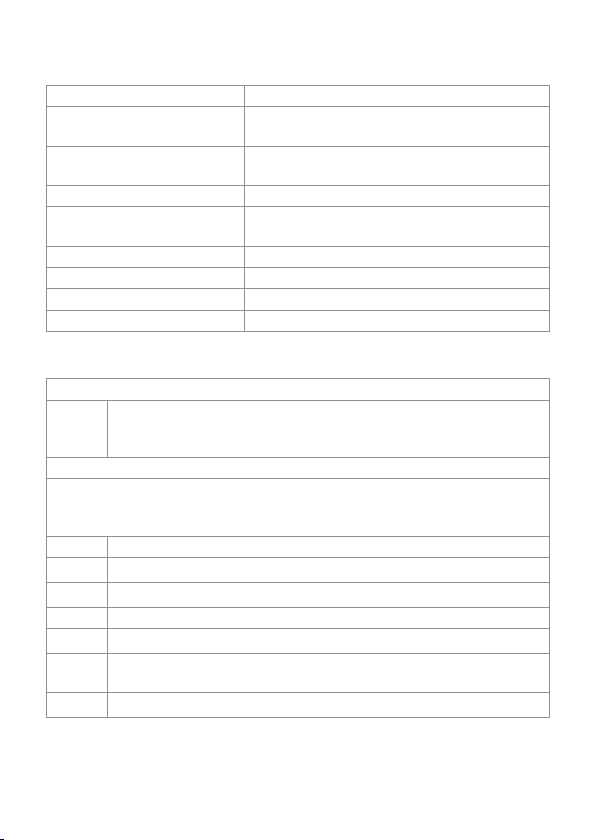
Dimensions/Abmessungen
All dimensions in mm/Alle Abmessungen in mm
71.5
63.5
56
microSD
Link
Activity
DMX/RDM Output Engine
Butler S2
EN.BU.0000001
Made in Italy
www.traxontechnologies.com
84.5
Setup Manual - Butler S2
24
Power input: 12 ... 24 V DC
Max. current: 250 mA
PWR
In
1 2 3 1 2 3
DMX/RDM
DMX2 DMX1
e:net
PoE
IEEE 802.3af
47

Downloads and more information at
www.traxontechnologies.com and www.ecue.com
HONG KONG SHANGHAI TOKYO SINGAPORE ROTTERDAM COLOGNE LONDON
MADRID MILAN PARIS ISTANBUL DENMARK MOSCOW WARSZAWA VIENNA
NEW YORK TORONTO DUBAI BUENOS AIRES MEXICO D.F. SAO PAULO COLOMBIA
MUMBAI
FLEXIBILITY, SIMPLICITY & INNOVATION IN LIGHTING SOLUTIONS & SERVICES
 Loading...