

Traxon Allegro Linear AC Series, Allegro Linear AC RGB, Allegro Linear AC RGBW, Allegro Linear AC SW, Allegro Linear AC DW Installation Manual
Page 1
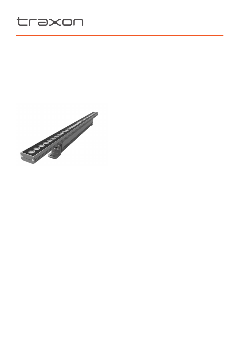
Allegro Linear AC
INSTALLATION GUIDE
V1.0
Cover:
Allegro Linear AC RGB
Allegro Linear AC RGBW
Allegro Linear AC DW
Allegro Linear AC SW (DMX)
Page 2
CONTENT
SAFETY AND OPERATION 3
1. INTRODUCTION 4
2. INSTALLATION 8
3. SYSTEM CONFIGURATION 13
4. CARE AND MAINTENANCE 15
5. TECHNICAL SPECIFICATION 16
6. TROUBLESHOOTING 18
7. WARRANTY STATEMENT 18
www.traxontechnologies.com
©2019 TRAXON TECHNOLOGIES - AN OSRAM BUSINESS. ALL RIGHTS RESERVED. TRAXON™, TX CONNECT®, ARE TRADEMARKS OF TRAXON TECHNOLOGIES. U.S. PATENTS, E.U.
PATENTS, JAPAN PATENTS, OTHER PATENTS PENDING. SPECIFICATIONS ARE SUBJECT TO CHANGE WITHOUT NOTICE.
Installation Guide 12/19 V1.0 P. 2 of 19
Page 3
SAFETY AND OPERATION
Please read through Safety and Operation before start of the installation.
1. CAUTION - Unplug the power supply from the mains power before connecting any
cables as this can damage the products.
2. CAUTION - Avoid looking directly into the LED light source at close range for your own
safety.
3. Persons installing this product should make sure:
a. The installation complies with all applicable codes, state and local laws, ordinances,
standards and safety regulations.
b. The installation environment is carefully studied and suitable surge protection
measure(s) is taken.
c. He or she is qualified for the handling of electrical equipment.
4. Do not attempt to install or use the product until installation instructions and safety labels
are fully understood. This product is designed for indoor and outdoor use.
5. Ensure product operates within the specified temperature range. (Refer to 5. TECHNICAL
SPECIFICATION for more details.)
6. Do not attempt to open the product. Not user serviceable.
7. Do not use the product if any part of it, or the power cables are damaged.
8. Only use product for specified voltage, do not exceed. (Refer to 5. TECHNICAL
SPECIFICATION for more details.)
9. Always maintain connection to ensure waterproofing.
10. If the product has been subjected to drastic temperature variances, for example,
following transportation, do not connect the fixture until it has reached room temperature,
as moisture condensation may cause electric shock and product damages.
11. When installing the products and system power supplies, please ensure they will not
be exposed to moisture and extreme heat (and direct sunlight for outdoor products).
Besides, keep a clean operating environment for the fixtures and system power supplies.
12. Please study this Installation Guide thoroughly and check the latest Technical
Specification Sheets available from the Traxon website www.traxontechnologies.com
before setup.
13. Any non-compliance of the Installation Guide will void the Traxon warranty.
www.traxontechnologies.com
©2019 TRAXON TECHNOLOGIES - AN OSRAM BUSINESS. ALL RIGHTS RESERVED. TRAXON™, TX CONNECT®, ARE TRADEMARKS OF TRAXON TECHNOLOGIES. U.S. PATENTS, E.U.
PATENTS, JAPAN PATENTS, OTHER PATENTS PENDING. SPECIFICATIONS ARE SUBJECT TO CHANGE WITHOUT NOTICE.
Installation Guide 12/19 V1.0 P. 3 of 19
Page 4
1. INTRODUCTION
1.1 General
The Allegro Linear AC series is a slim profile, AC line powered high brightness luminaire. The
series is controllable via DMX512, and is available in four lengths. The luminaire can be simply
daisy-chained to form long runs.
Model Power Consumption (W) Length (mm)
Allegro Linear AC 300 15 320
Allegro Linear AC 600 28 615
Allegro Linear AC 900 41 915
Allegro Linear AC 1200 55 1215
Features:
• Outdoor applications
• Protection Class IP66
• Suitable for coastal environments
• Impact rating IK07
• Windforce compliant to IEC 60598-2-3
• Vibration compliant to 3G ANSI C136.31
• Input voltage: 220-240V AC, 120V/277V AC 50/60Hz
• Integrated mounting feet with ±90° adjustment on beam aiming
• DMX512
• Remote Device Management (RDM)
• CE, cETLus
• DynaMood
®
: BinOne · BoostOne · AddressOne
www.traxontechnologies.com
©2019 TRAXON TECHNOLOGIES - AN OSRAM BUSINESS. ALL RIGHTS RESERVED. TRAXON™, TX CONNECT®, ARE TRADEMARKS OF TRAXON TECHNOLOGIES. U.S. PATENTS, E.U.
PATENTS, JAPAN PATENTS, OTHER PATENTS PENDING. SPECIFICATIONS ARE SUBJECT TO CHANGE WITHOUT NOTICE.
Installation Guide 12/19 V1.0 P. 4 of 19
Page 5
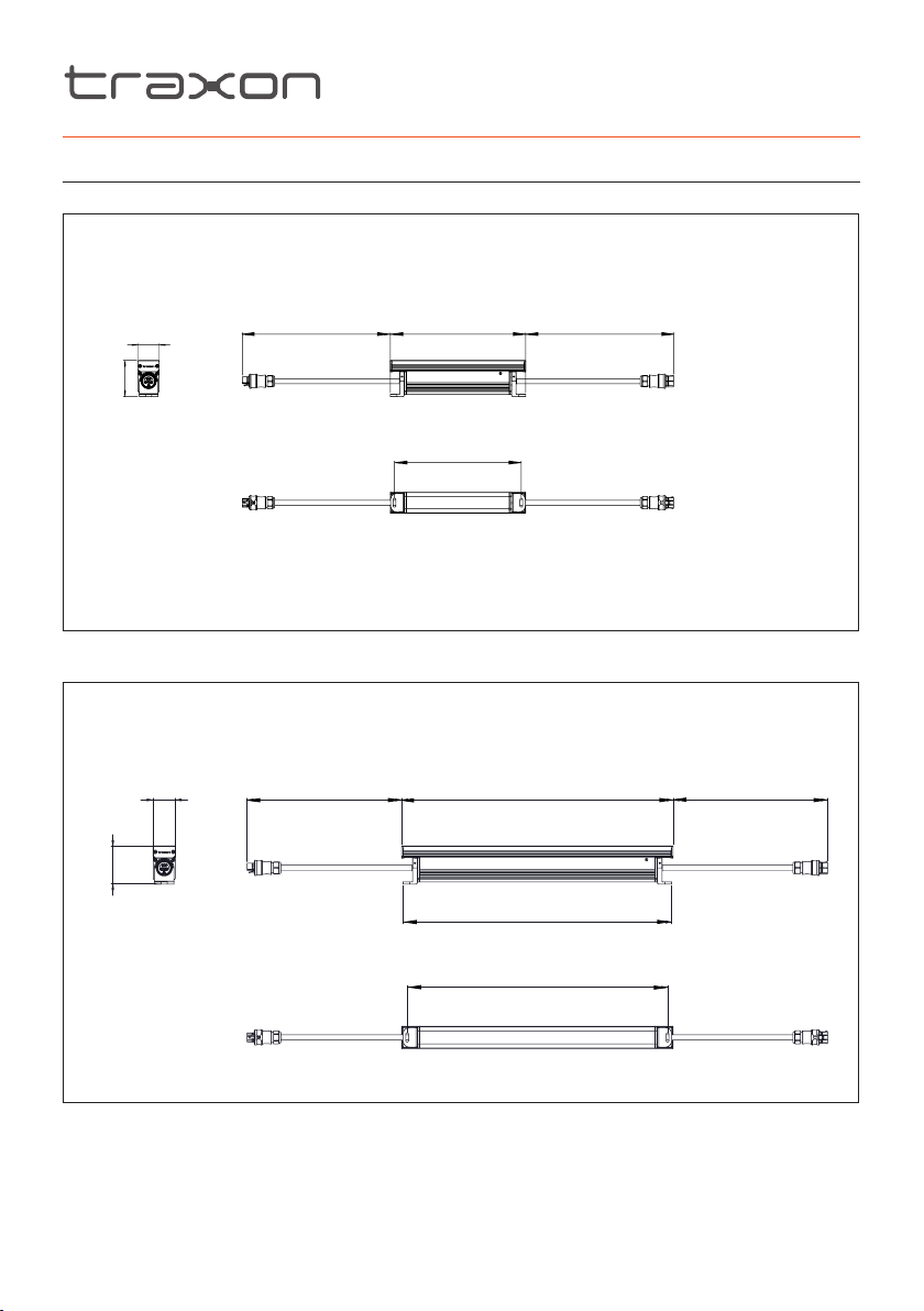
1.2 Dimensions
320mm/12.6”
350mm/13.8”
300mm/11.8”
50mm/1.97”
86mm/3.4”
350mm/13.8”
FIG.1: Allegro Linear AC 300
FIG.2: Allegro Linear AC 600
50mm/1.97”
350mm/13.8”
615mm/24.2”
350mm/13.8”
86mm/3.4”
610mm/24”
590mm/23.2”
www.traxontechnologies.com
©2019 TRAXON TECHNOLOGIES - AN OSRAM BUSINESS. ALL RIGHTS RESERVED. TRAXON™, TX CONNECT®, ARE TRADEMARKS OF TRAXON TECHNOLOGIES. U.S. PATENTS, E.U.
PATENTS, JAPAN PATENTS, OTHER PATENTS PENDING. SPECIFICATIONS ARE SUBJECT TO CHANGE WITHOUT NOTICE.
Installation Guide 12/19 V1.0 P. 5 of 19
Page 6
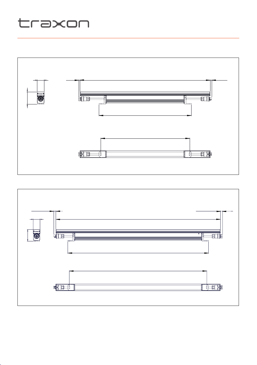
FIG.3: Allegro Linear AC 900
86mm/3.4”
50mm/1.97”
10mm/0.4”
86mm/3.4”
FIG.4: Allegro Linear AC 1200
10mm/0.4”
50mm/1.97”
915mm/36.0”
649mm/25.6”
625mm/24.6”
1215mm/47.8”
1039mm/40.9”
10mm/0.4”
10mm/0.4”
1015mm/40.0”
www.traxontechnologies.com
©2019 TRAXON TECHNOLOGIES - AN OSRAM BUSINESS. ALL RIGHTS RESERVED. TRAXON™, TX CONNECT®, ARE TRADEMARKS OF TRAXON TECHNOLOGIES. U.S. PATENTS, E.U.
PATENTS, JAPAN PATENTS, OTHER PATENTS PENDING. SPECIFICATIONS ARE SUBJECT TO CHANGE WITHOUT NOTICE.
Installation Guide 12/19 V1.0 P. 6 of 19
Page 7
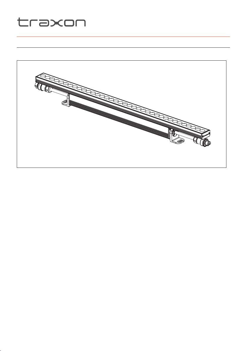
1.3 Packing Contents
FIG.5: Packing Contents
1 x Allegro Linear AC
www.traxontechnologies.com
©2019 TRAXON TECHNOLOGIES - AN OSRAM BUSINESS. ALL RIGHTS RESERVED. TRAXON™, TX CONNECT®, ARE TRADEMARKS OF TRAXON TECHNOLOGIES. U.S. PATENTS, E.U.
PATENTS, JAPAN PATENTS, OTHER PATENTS PENDING. SPECIFICATIONS ARE SUBJECT TO CHANGE WITHOUT NOTICE.
Installation Guide 12/19 V1.0 P. 7 of 19
Page 8
2. INSTALLATION
2.1 Points To Consider
Plan your installation before mounting any Allegro Linear AC. The following should
be considered for a successful installation:
• Weather conditions and ambient temperature of installation site.
• Installation distances and appropriate cable lengths. Please consult your local Traxon™
office or authorized agent for necessary aid.
• The number of Allegro Linear AC and appropriate power sources.
• Distance between each Allegro Linear AC for thermal expansion.
• Proper surge protection.
2.1.1 Installation Checklist
1. Prepare cables and all necessary accessories.
2. Perform functional check of Allegro Linear AC. Take care not to damage cables/
connectors during pre-installation checks.
3. Ensure all pre-installation checks laid out below have been followed.
4. Mount the Allegro Linear AC on-site. If the installation is to be left uncompleted overnight,
place all non-connected LED Engines and Allegro Linear AC in an indoor environment.
Ensure all the Interconnection Cables, Allegro Linear AC and power sources
are initially stored in a dry area to guarantee the complete sealing of the
system from water before installation.
www.traxontechnologies.com
©2019 TRAXON TECHNOLOGIES - AN OSRAM BUSINESS. ALL RIGHTS RESERVED. TRAXON™, TX CONNECT®, ARE TRADEMARKS OF TRAXON TECHNOLOGIES. U.S. PATENTS, E.U.
PATENTS, JAPAN PATENTS, OTHER PATENTS PENDING. SPECIFICATIONS ARE SUBJECT TO CHANGE WITHOUT NOTICE.
Installation Guide 12/19 V1.0 P. 8 of 19
Page 9
2.2 Pre-Installation Checks
2.2.1 Sequence For Cable And Connector Preparation
1. Trim Cable.
2. Plan for any possible bending of cables.
3. Fix cable ends with connectors.
4. Complete sealing of connectors by tightening screw nut with spanner/wrench.
5. Unplug Dust Caps/Waterproof End Caps and keep safe for reuse.
6. Connect luminaries with power sources and data injector boxes with connection cables
in the daisy-chain manner described in the wiring diagram.
7. Open Short Test should be performed to ensure cable wires are connected correctly. Recrimping of wires should be done if any failures occur.
8. Perform functional check on all Allegro Linear AC.
9. Report any functional defect found to your nearest Traxon Technologies office. DO NOT
attempt to install an Allegro Linear AC with functional defects on-site.
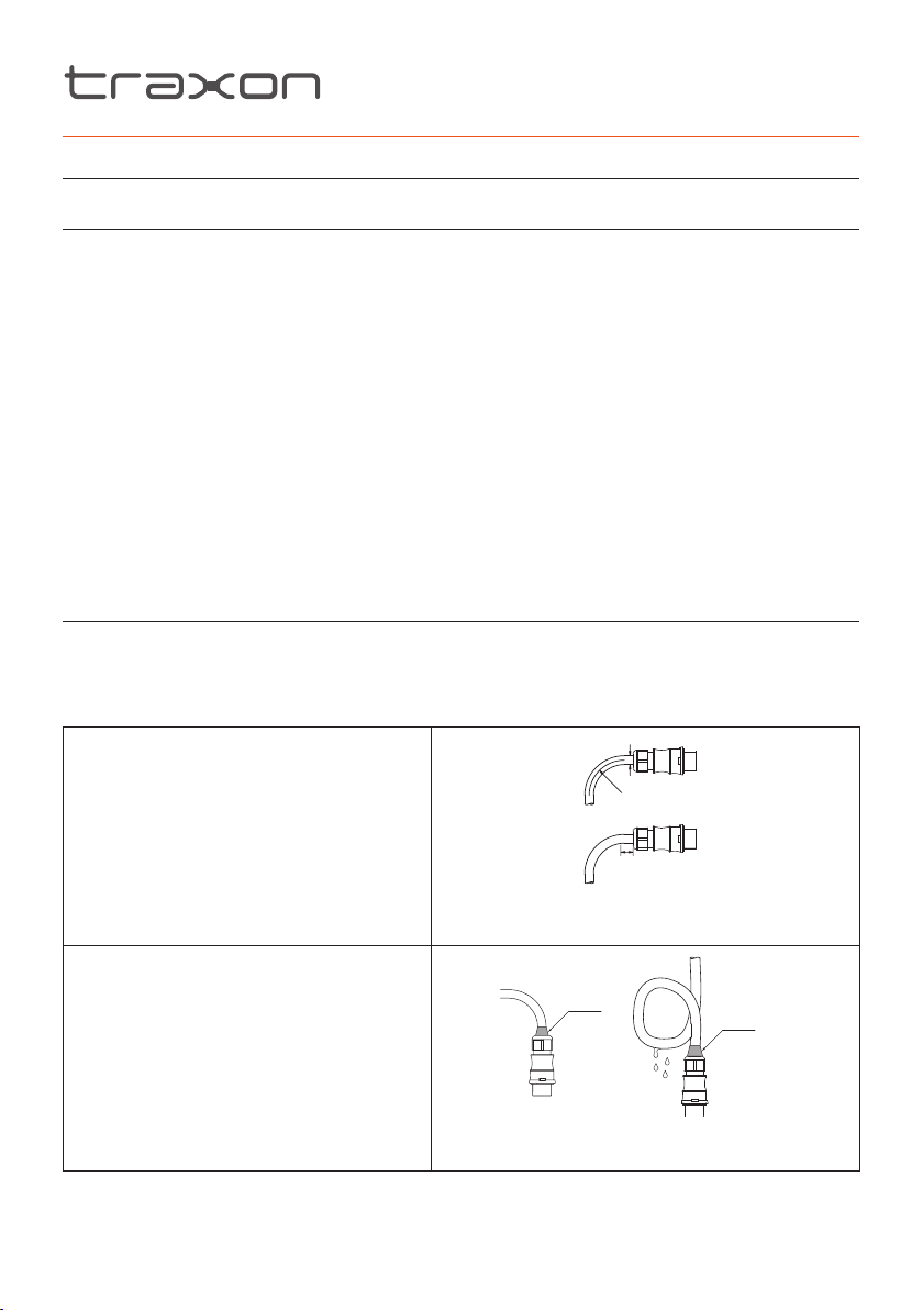
2.2.2 Cable Bending
Cable must NOT be bent below the Minimum Bending Radius (4 x Cable Diameter) as
specified by cable manufacturer and the Non-Bendable Length of 5cm near the connector
end MUST be adhered to.
a
Bending radius (for conductors):
Note the minimum bending radius for
conductors > 1.5mm2.
Pull forces on the contact points can be
avoided by proceeding as follows:
a – Bend the wire as required
(Minimum Bending Radius)
FIG.6: Cable Bending
D
≥4D
5cm
(Non-Bendable Length)
Avoid vertical placement of the
connectors.
If vertical installation is unavoidable:
Silicone Glue
Silicone Glue
• Add silicon glue on the surface of cable
gland.
• Layout the cable to have drip loop to
allow water run off the wire.
FIG.7: Connector vertical installation warning
www.traxontechnologies.com
©2019 TRAXON TECHNOLOGIES - AN OSRAM BUSINESS. ALL RIGHTS RESERVED. TRAXON™, TX CONNECT®, ARE TRADEMARKS OF TRAXON TECHNOLOGIES. U.S. PATENTS, E.U.
PATENTS, JAPAN PATENTS, OTHER PATENTS PENDING. SPECIFICATIONS ARE SUBJECT TO CHANGE WITHOUT NOTICE.
Installation Guide 12/19 V1.0 P. 9 of 19
Page 10
2.3 On-Site Installation
• DO NOT attempt installation in wet or severe weather conditions.
• DO NOT leave and expose any Allegro Linear AC or power sources
unconnected under wet/raining or snowing environment.
• IP failure induced by stressed/damaged cables during or after installation
will not be under warranty by Traxon Technologies.
• ALWAYS keep the cables protected from sharp objects and ensure no
damage is generated on the cable.
• Failure to keep Allegro Linear AC within the operating temperature range
of –30°C to +50°C (–22°F to +122°F) and storage temperature range of
–40°C to +70°C (–40°F to +158°F) will void the product’s warranty.
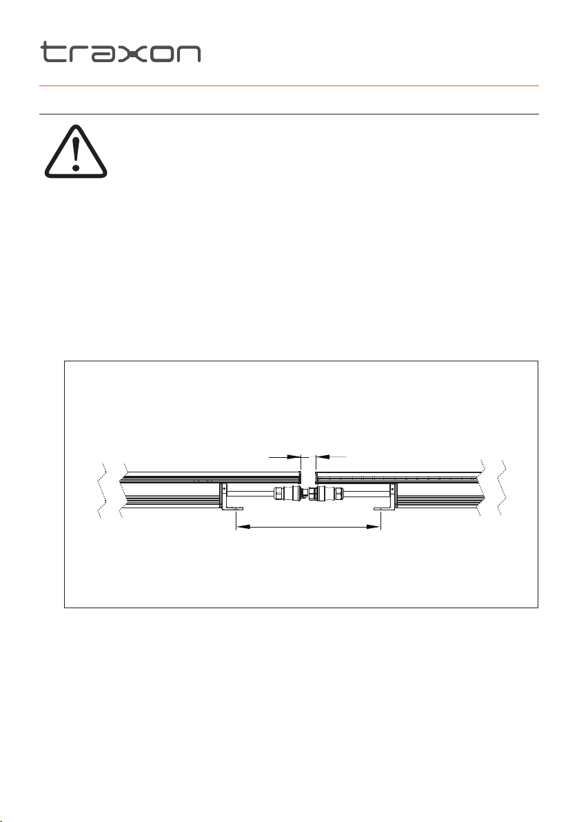
1. Do not leave and expose Allegro Linear AC without Dust Cap plugged under wet/raining
or snowing environment as the Allegro Linear AC is not IP66 compliant unless properly
connected. Make sure there is a minimum spacing of 5mm/0.2” between Allegro Linear
AC for thermal expansion.
FIG.8: Min. clearance between fixtures
Min.
5mm/0.2”
X Y
www.traxontechnologies.com
©2019 TRAXON TECHNOLOGIES - AN OSRAM BUSINESS. ALL RIGHTS RESERVED. TRAXON™, TX CONNECT®, ARE TRADEMARKS OF TRAXON TECHNOLOGIES. U.S. PATENTS, E.U.
PATENTS, JAPAN PATENTS, OTHER PATENTS PENDING. SPECIFICATIONS ARE SUBJECT TO CHANGE WITHOUT NOTICE.
Installation Guide 12/19 V1.0 P. 10 of 19
Page 11
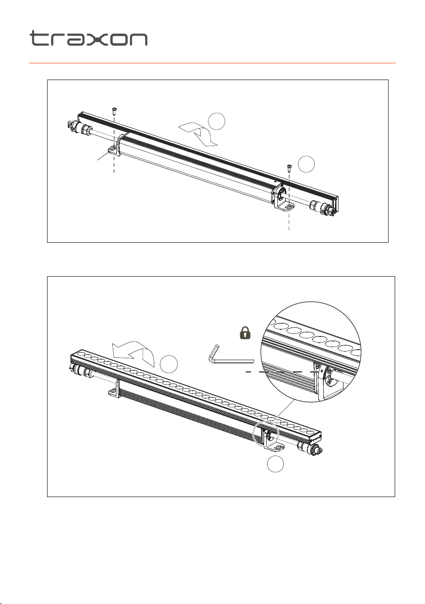
2. Rotate fixture to gain access to mounting holes.
FIG.9: Mounting
6mm screw (x2)
(not included)
1
Mounting
Bracket
3. Fix screws to mounting brackets.
4. Tilt the Allegro Linear AC head to the desired angle.
FIG.10: Locking fixture position
1
2.5mm
2
2
5. Then tighten lock screws with provided Hex Key in clockwise direction.
6. Unplug the Dust Caps/Waterproof End Caps and keep them in a container for reuse.
www.traxontechnologies.com
©2019 TRAXON TECHNOLOGIES - AN OSRAM BUSINESS. ALL RIGHTS RESERVED. TRAXON™, TX CONNECT®, ARE TRADEMARKS OF TRAXON TECHNOLOGIES. U.S. PATENTS, E.U.
PATENTS, JAPAN PATENTS, OTHER PATENTS PENDING. SPECIFICATIONS ARE SUBJECT TO CHANGE WITHOUT NOTICE.
Installation Guide 12/19 V1.0 P. 11 of 19
Page 12
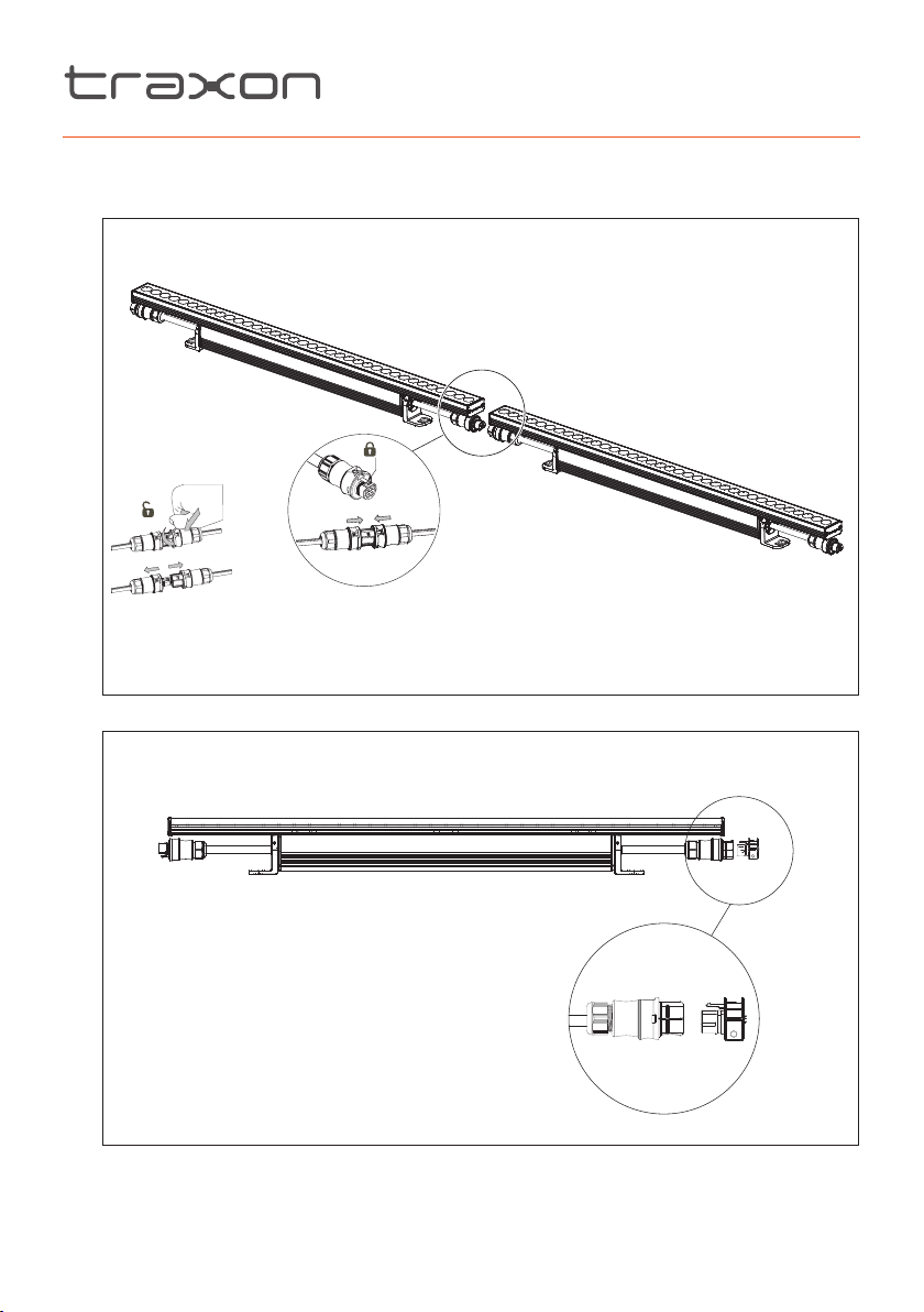
7. Fully connect all the Allegro Linear AC with connection cables one after the other. Do
!
not work on the other unit’s connections until the first unit under installation is properly
connected.
FIG.11: Interconnecting fixtures
8. Please use end cap for final fixture in connection chain.
FIG.12: Install the end cap
www.traxontechnologies.com
©2019 TRAXON TECHNOLOGIES - AN OSRAM BUSINESS. ALL RIGHTS RESERVED. TRAXON™, TX CONNECT®, ARE TRADEMARKS OF TRAXON TECHNOLOGIES. U.S. PATENTS, E.U.
PATENTS, JAPAN PATENTS, OTHER PATENTS PENDING. SPECIFICATIONS ARE SUBJECT TO CHANGE WITHOUT NOTICE.
Installation Guide 12/19 V1.0 P. 12 of 19
Page 13
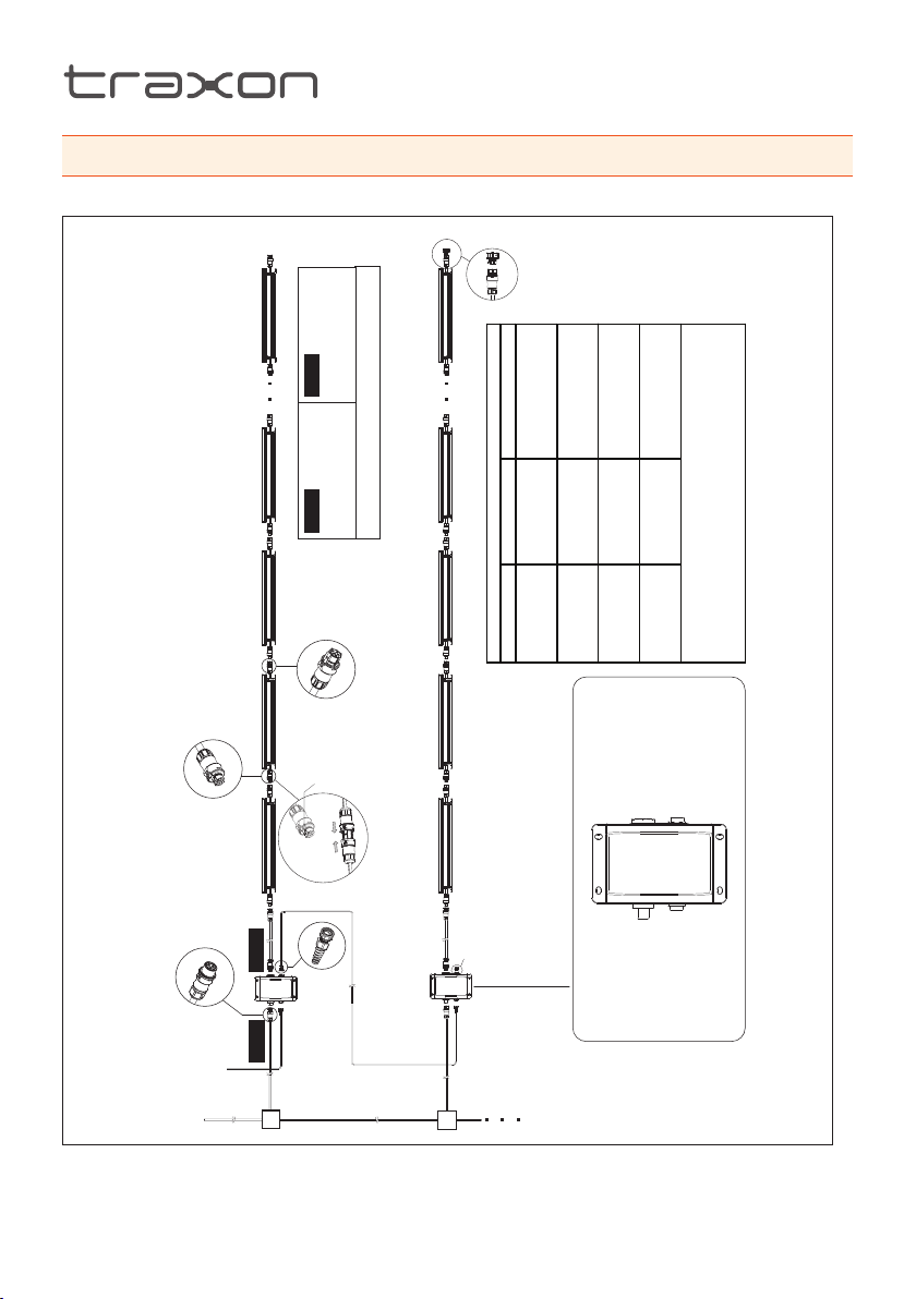
3. SYSTEM CONFIGURATION
CLICK!
FIG.13: System Diagram for CE
(CE)
2
Use end cap for
final fixture in chain
XB.AC.2304000
5-pin Male
connector
3-pin Female
connector
DMX In
Cable B
Cable A
Outside Ø10-14mm
Cable B
H07RN-F 5G 2.5mm
(CE)
2
Outside Ø10-14mm
Cable A
H07RN-F 3G 2.5mm
Ensure locking clip
is present when
making a connection
DMX Out
RJ45 Male Connector
Housing IP67
DE.AC.0100000
Use Traxon accessory parts to ensure installation compatibility.
Failure to do so can void the warranty.
Fixture Voltage Max. number of fixt ures
Fixture daisy chain per Data Injector:
5-pin Female
connector
Use provided end cap for
final data injector in chain
To construct a longer data cable,
use outdoor data cable with RJ45 housing.
Outdoor cable specification:
CAT-5e UTP/FTP
PVC jacket; UV resistant
Outer diameter 6mm/0.24”
Filled type
220-240V CE 86
220-240V CE 128
600
300
Quattro
Data Injector
220-240V CE 62
220-240V CE 47
900
1200
RJ45RJ45
5-pin Female connector
3-pin Male connector
s office to
r cable leng ths are used. Please consult regional sale
Max. number of fixt ures is based o n minimal interconnection leng ths between Data
Injector-to-Fixture and Fix ture-to-Fix ture.
Actual number of fix tures is dependent on cable interconnection lengths. Number of
fixtures will reduce if longe
confirm maximums.
Mains AC ~
www.traxontechnologies.com
©2019 TRAXON TECHNOLOGIES - AN OSRAM BUSINESS. ALL RIGHTS RESERVED. TRAXON™, TX CONNECT®, ARE TRADEMARKS OF TRAXON TECHNOLOGIES. U.S. PATENTS, E.U.
PATENTS, JAPAN PATENTS, OTHER PATENTS PENDING. SPECIFICATIONS ARE SUBJECT TO CHANGE WITHOUT NOTICE.
Installation Guide 12/19 V1.0 P. 13 of 19
Page 14
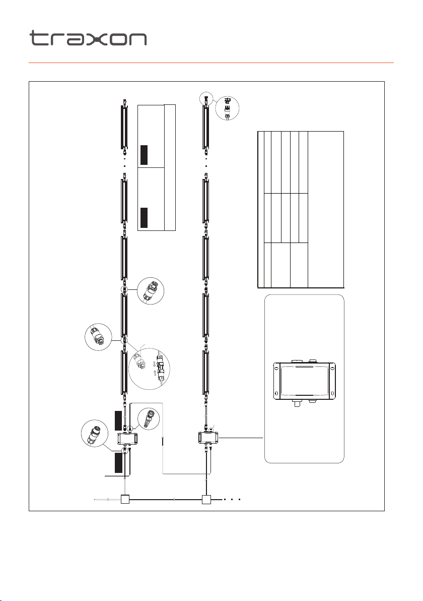
FIG.14: System Diagram for ETL
CLICK!
Outside Ø10-14mm
Use end cap for
final fixture in chain
XB.AC.2304000
5-pin Male
connector
3-pin Female
connector
DMX In
Cable B
Cable A
SJTW 5C AWG14 (UL)
Cable B
Outside Ø6-10mm
SJTW 3C AWG14 (UL)
Cable A
Ensure locking clip
is present when
making a connection
DMX Out
RJ45 Male Connector
Housing IP67
DE.AC.0100000
Use Traxon accessory parts to ensure installation compatibility.
Failure to do so can void the warranty.
5-pin Female
connector
Use provided end cap for
final data injector in chain
To construct a longer data cable,
use outdoor data cable with RJ45 housing.
Outdoor cable specification:
CAT-5e UTP/FTP
PVC jacket; UV resistant
Outer diameter 6mm/0.24”
Filled type
Fixture daisy chain per Data Injector:
120-127V ETL 45
Fixture Voltage Max. number of fixt ures
Quattro
Data Injector
1ft
22
277V ETL 57
277V ETL 128
120-127V ETL
4ft
Max. number of fixt ures is based o n minimal interconnection leng ths between Data
RJ45RJ45
5-pin Female connector
3-pin Male connector
r cable leng ths are used. Please consult regional sales office t o
onfirm maximums.
Injector-to-Fixture and Fix ture-to-Fix ture.
Actual number of fix tures is dependent on cable interconnection lengths. Number of
fixtures will reduce if longe
c
Mains AC ~
www.traxontechnologies.com
©2019 TRAXON TECHNOLOGIES - AN OSRAM BUSINESS. ALL RIGHTS RESERVED. TRAXON™, TX CONNECT®, ARE TRADEMARKS OF TRAXON TECHNOLOGIES. U.S. PATENTS, E.U.
PATENTS, JAPAN PATENTS, OTHER PATENTS PENDING. SPECIFICATIONS ARE SUBJECT TO CHANGE WITHOUT NOTICE.
Installation Guide 12/19 V1.0 P. 14 of 19
Page 15

4. CARE AND MAINTENANCE
• Traxon™ products are of superior design and quality and should be treated with care. The
recommendations below will help fulfill any warranty obligations and gain good use and
longevity from the products.
• Do not attempt or use the product(s) until you read and understand the installation
instructions. Failure to adhere to these instructions could result in serious injury or property
damage.
• Do not use product(s) if cables are damaged.
• Do not connect cables and connectors when wet or in wet area. Moisture on bare
connectors can cause electric shock and damage to product(s).
• Do not use product(s) in extreme heat environment. Ensure there is sufficient airflow and
use cool air circulation if required.
• Do not drop, knock, or shake product(s). Rough handling can damage the electronics and
void the warranty.
• Do not use harsh chemicals, cleaning solvents, or strong detergents to clean products.
Wipe with a damp cloth on housings and a dry cloth on electronics to remove dirt or dust.
• Do not attempt to service or repair the product(s) unless done by an authorized service
personnel. Contact your local Traxon office or distributor for details.
• If the product is not working as specified, please contact your nearest authorized service
center or Traxon Technologies office for assistance.
www.traxontechnologies.com
©2019 TRAXON TECHNOLOGIES - AN OSRAM BUSINESS. ALL RIGHTS RESERVED. TRAXON™, TX CONNECT®, ARE TRADEMARKS OF TRAXON TECHNOLOGIES. U.S. PATENTS, E.U.
PATENTS, JAPAN PATENTS, OTHER PATENTS PENDING. SPECIFICATIONS ARE SUBJECT TO CHANGE WITHOUT NOTICE.
Installation Guide 12/19 V1.0 P. 15 of 19
Page 16
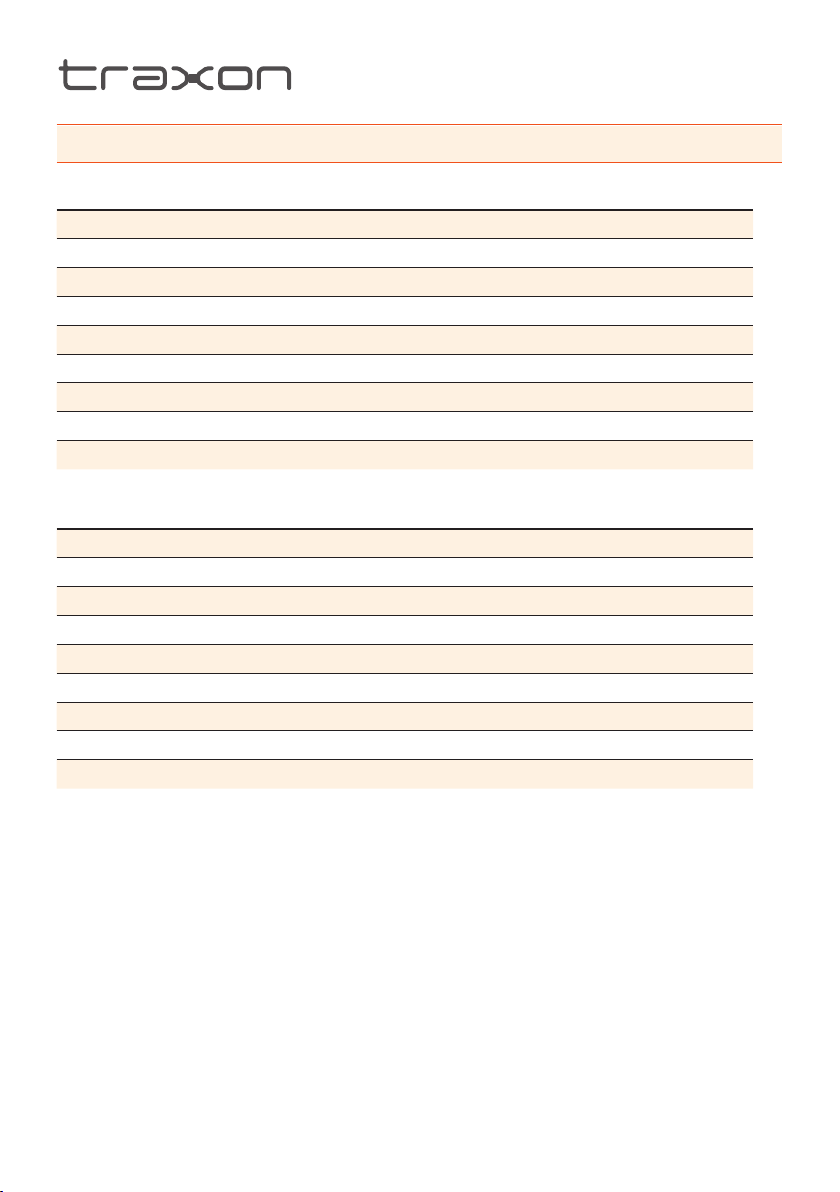
5. TECHNICAL SPECIFICATION
RGBW
300 600 900 1200
Light Source High power LEDs
Color Range RGBW (white CCT 3000K)
Beam Angle 10°, 40°, 60° × 10°, 60° × 30°
Power Input 220-240V AC, 120/277V AC 50/60Hz
Power Consumption 15W 28W 41W 55W
Weight 2.0kg/4.4lb 3.3kg/7.3lb 4.0kg/8.8lb 5.5kg/12.1lb
Operating Temperature −30°C to +50°C / −22°F to +122°F (−20°C / −4°F starting)
Storage Temperature −40°C to +70°C / −40°F to +158°F
RGB
300 600 900 1200
Light Source High power LEDs
Color Range RGB
Beam Angle 10°, 40°, 60° × 10°, 60° × 30°
Power Input 220-240V AC, 120/277V AC 50/60Hz
Power Consumption 15W 28W 41W 55W
Weight 2.0kg/4.4lb 3.3kg/7.3lb 4.0kg/8.8lb 5.5kg/12.1lb
Operating Temperature −30°C to +50°C / −22°F to +122°F (−20°C / −4°F starting)
Storage Temperature −40°C to +70°C / −40°F to +158°F
www.traxontechnologies.com
©2019 TRAXON TECHNOLOGIES - AN OSRAM BUSINESS. ALL RIGHTS RESERVED. TRAXON™, TX CONNECT®, ARE TRADEMARKS OF TRAXON TECHNOLOGIES. U.S. PATENTS, E.U.
PATENTS, JAPAN PATENTS, OTHER PATENTS PENDING. SPECIFICATIONS ARE SUBJECT TO CHANGE WITHOUT NOTICE.
Installation Guide 12/19 V1.0 P. 16 of 19
Page 17
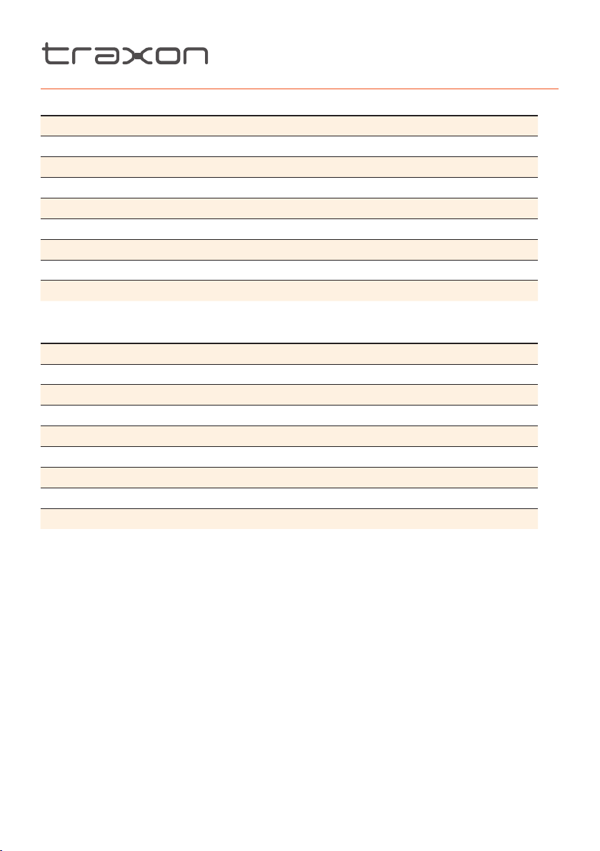
DW
300 600 900 1200
Light Source High power LEDs
Color Range Dynamic White (2700K-5700K)
Beam Angle 10°, 40°, 60° × 10°, 60° × 30°
Power Input 220-240V AC, 120/277V AC 50/60Hz
Power Consumption 15W 28W 41W 55W
Weight 2.0kg/4.4lb 3.3kg/7.3lb 4.0kg/8.8lb 5.5kg/12.1lb
Operating Temperature −30°C to +50°C / −22°F to +122°F (−20°C / −4°F starting)
Storage Temperature −40°C to +70°C / −40°F to +158°F
SW
300 600 900 1200
Light Source High power LEDs
Color Range 2700K, 3000K, 4000K, 5700K
Beam Angle 10°, 40°, 60° × 10°, 60° × 30°
Power Input 220-240V AC, 120/277V AC 50/60Hz
Power Consumption 15W 28W 41W 55W
Weight 2.0kg/4.4lb 3.3kg/7.3lb 4.0kg/8.8lb 5.5kg/12.1lb
Operating Temperature −30°C to +50°C / −22°F to +122°F (−20°C / −4°F starting)
Storage Temperature −40°C to +70°C / −40°F to +158°F
As with all electronic devices, LED output degrades over time - a term called lumen
depreciation. This also explains why it is nearly impossible to expect photometric
performances of two LED products with different service life spans to be the same. The
rate of LED degradation is a complex function of many factors such as operating efficiency,
duration of continuous operation, and operating conditions (e.g. ambient temperature).
Because LEDs are semiconductor devices, their performances are subject to inherent
variability commonly found in semiconductor industry. To improve consistency in performance
across the same product, LED manufacturers “sort” LEDs into bins according to different
preset parameters, such as forward driving voltage, illumination, etc. Whereas binning is a
sorting function, it is not a correction process. Inherent variability in the manufacturing process
always results in different binning distributions according to different production lots. Traxon
uses automatically binned LEDs on its products, thereby minimizing output variations within
the model range.
www.traxontechnologies.com
©2019 TRAXON TECHNOLOGIES - AN OSRAM BUSINESS. ALL RIGHTS RESERVED. TRAXON™, TX CONNECT®, ARE TRADEMARKS OF TRAXON TECHNOLOGIES. U.S. PATENTS, E.U.
PATENTS, JAPAN PATENTS, OTHER PATENTS PENDING. SPECIFICATIONS ARE SUBJECT TO CHANGE WITHOUT NOTICE.
Installation Guide 12/19 V1.0 P. 17 of 19
Page 18
6. TROUBLESHOOTING
Caution: Ensure power supply is OFF when disconnecting / connecting
cables.
Problem Cause Possible Solutions
Product does
NOT light up
after installation
Shadowing Light source covered • Check for cables, wires or unwanted
Modules are
dim
Flickering Incorrect power input/
If problems persist or the product is not working as specified, please contact your nearest
authorized service center or Traxon Technologies office for assistance.
Incorrect power
connection
Excess products
connected
Excess products
connected
• Check Mains Power
• Check power supply leads and wire
connections
• Ensure output wires are connected with
proper polarity
debris covering LED light source
• Ensure the power supplies are not
overloaded due to an excess of products
connected
• Ensure the input voltage is correct
• Ensure the power supplies are not
overloaded due to an excess of products
connected
7. WARRANTY STATEMENT
Traxon Technologies warrants its Products against material or workmanship defects from date
of purchase, provided that the purchased items are used under the conditions stated in this
user manual.
Please refer www.traxontechnologies.com for all warranty terms and conditions.
www.traxontechnologies.com
©2019 TRAXON TECHNOLOGIES - AN OSRAM BUSINESS. ALL RIGHTS RESERVED. TRAXON™, TX CONNECT®, ARE TRADEMARKS OF TRAXON TECHNOLOGIES. U.S. PATENTS, E.U.
PATENTS, JAPAN PATENTS, OTHER PATENTS PENDING. SPECIFICATIONS ARE SUBJECT TO CHANGE WITHOUT NOTICE.
Installation Guide 12/19 V1.0 P. 18 of 19
Page 19

Please check for the latest updates and changes on the Traxon website.
© 2019 TRAXON TECHNOLOGIES ALL RIGHTS RESERVED. Information is subject to change without prior notice.
www.traxontechnologies.com
 Loading...