

Traxon 64PXL Installation Manual
64PXL Board RGB
INSTALLATION GUIDE
V1.3
Cover:
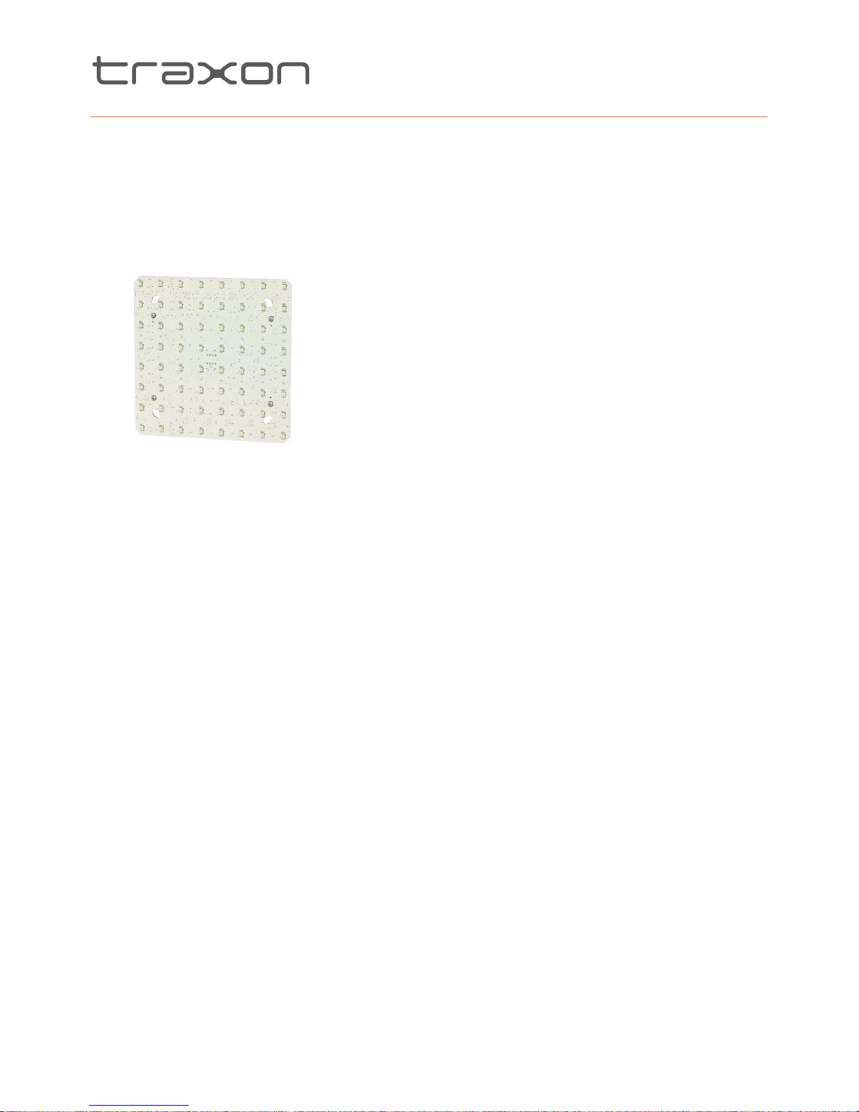
64PXL Board RGB
8PXL Add-On Strip
16PXL Add-On Board
Discontinued
www.traxontechnologies.com
©2015 TRAXON TECHNOLOGIES - AN OSRAM BUSINESS. ALL RIGHTS RESERVED. TRAXON™, TX CONNECT®, ARE TRADEMARKS OF TRAXON TECHNOLOGIES. U.S. PATENTS, E.U.
PATENTS, JAPAN PATENTS, OTHER PATENTS PENDING. SPECIFICATIONS ARE SUBJECT TO CHANGE WITHOUT NOTICE.
Installation Guide 05/15 V1.3 2 of 18
CONTENT
1. INTRODUCTION 3
2. INSTALLATION 5
3. SAFETY AND OPERATION 7
4. SYSTEM CONFIGURATION 8
5. CARE AND MAINTENANCE 12
6. TECHNICAL SPECIFICATION 13
7. TROUBLESHOOTING 14
8. WARRANTY STATEMENT 14
9. ADD-ON FIXTURES 15
For your own safety and that of the product, please read this installation guide
carefully before beginning setup and installation.
Discontinued
www.traxontechnologies.com
©2015 TRAXON TECHNOLOGIES - AN OSRAM BUSINESS. ALL RIGHTS RESERVED. TRAXON™, TX CONNECT®, ARE TRADEMARKS OF TRAXON TECHNOLOGIES. U.S. PATENTS, E.U.
PATENTS, JAPAN PATENTS, OTHER PATENTS PENDING. SPECIFICATIONS ARE SUBJECT TO CHANGE WITHOUT NOTICE.
Installation Guide 05/15 V1.3 3 of 18
INTRODUCTION1.
General1.1
64PXL Board RGB features 64 ultra bright RGB SMD LEDs on a 8 x 8matrix with a
31.25mm/1.23” pitch. Although the LEDs provide ultra brightness, high resolution videos
and graphic replays can be created by combining multiple boards. The 64PXL Board is DMX
compatible which allows daisy chaining with the Traxon TX Connect™ system. On-board
SMART CHIP™ technology with the powerful feature of auto-addressing enables easy setup
and installation.
Features:
64 Ultra Bright RGB SMD LEDs
t
TX Connect™ Systemt
DMX512 / e:pix / DVI capablet
Auto-Addressingt
SMART CHIP™ Technologyt
Indoor Applicationst
Discontinued
www.traxontechnologies.com
©2015 TRAXON TECHNOLOGIES - AN OSRAM BUSINESS. ALL RIGHTS RESERVED. TRAXON™, TX CONNECT®, ARE TRADEMARKS OF TRAXON TECHNOLOGIES. U.S. PATENTS, E.U.
PATENTS, JAPAN PATENTS, OTHER PATENTS PENDING. SPECIFICATIONS ARE SUBJECT TO CHANGE WITHOUT NOTICE.
Installation Guide 05/15 V1.3 4 of 18
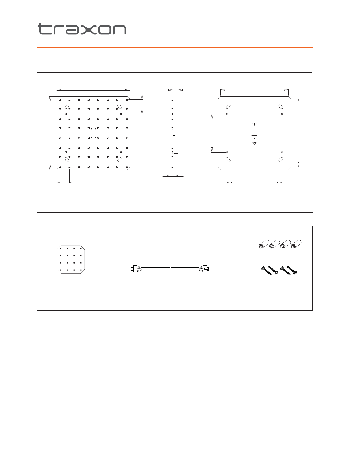
Dimensions1.2
64PXL Board RGB DimensionsFIG.1:
240mm/9.45”
31.25mm/1.23” (typ.)
4.32mm/0.17”
16.00mm/0.63”
31.25mm/1.23” (typ.)
222mm/8.74”
180mm/7.09” (2x)
125mm/4.92” (2x)
222mm/8.74”
Packing Contents1.3
Packing ContentsFIG.2:
1 x TX Connect Smart Interconnection Cable (300mm/11.82”)
4 x Mounting Spacers
1 x 64PXL Board RGB
4 x Mounting Screws
Discontinued
www.traxontechnologies.com
©2015 TRAXON TECHNOLOGIES - AN OSRAM BUSINESS. ALL RIGHTS RESERVED. TRAXON™, TX CONNECT®, ARE TRADEMARKS OF TRAXON TECHNOLOGIES. U.S. PATENTS, E.U.
PATENTS, JAPAN PATENTS, OTHER PATENTS PENDING. SPECIFICATIONS ARE SUBJECT TO CHANGE WITHOUT NOTICE.
Installation Guide 05/15 V1.3 5 of 18
INSTALLATION2.
Points To Consider2.1
Plan your installation before mounting the String. The following should be considered for a
successful installation.
Installation distances and appropriate cable lengths. Please consult your local Traxon™
t
office or authorized agent for necessary aid.
The number of 64PXL Board RGBs and appropriate LED Engines.
t
Any DMX512 controllers to be used with the products.t
On-Site Installation2.2
ALWAYS keep the cables protected from sharp objects and ensure no t
damage is generated on the cables.
Failure to keep the product within the operating temperature range of 0°C t
to 50°C (+32°F to +122°F) and storage temperature range of −20°C to
+70°C (–4°F to +158°F) will void the product’s warranty.
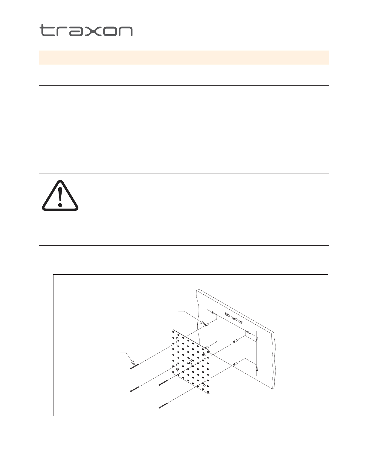
Mounting2.2.1
To mount the board, first fit the nylon spacers into the mounting holes from the rear of 1.
the board. Then use the screws to firmly fasten the board to a flat surface. Careful not to
over-tighten the screws, see below diagram.
Board MountingFIG.3:
125mm/4.92”
SCREW (4x)
MOUNTING SPACER (4x)
Discontinued

www.traxontechnologies.com
©2015 TRAXON TECHNOLOGIES - AN OSRAM BUSINESS. ALL RIGHTS RESERVED. TRAXON™, TX CONNECT®, ARE TRADEMARKS OF TRAXON TECHNOLOGIES. U.S. PATENTS, E.U.
PATENTS, JAPAN PATENTS, OTHER PATENTS PENDING. SPECIFICATIONS ARE SUBJECT TO CHANGE WITHOUT NOTICE.
Installation Guide 05/15 V1.3 6 of 18
To keep a consistent LED pitch when mounting multiple boards, use the dimensions 2.
shown in below diagram.
Mounting Multiple BoardsFIG.4:
180mm/7.09”30mm/1.81” 70mm/2.76”
10mm/0.39”
31.25mm/1.23”
31.25mm/1.23”
31.25mm/1.23”
31.25mm/1.23”
31.25mm/1.23”
31.25mm/1.23”
180mm/7.09”
125mm/4.92” 125mm/4.92” 125mm/4.92” 57.5mm/2.26”
10mm/0.39”
Discontinued
 Loading...