

Page 1
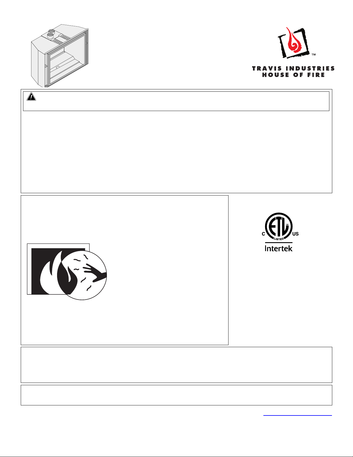
430 Ember-Glo™
GSR2 Insert
Owner’s Manual
WARNING: FIRE OR EXPLOSION HAZARD
Failure to follow safety warnings exactly could result in serious injury, death, or property damage.
- Do not store or use gasoline or other flammable vapors and liquids in the vicinity of this or any
other appliance.
- WHAT TO DO IF YOU SMELL GAS
• Do not try to light any appliance.
• Do not touch any electrical switch; do not use any phone in your building.
• Leave the building immediately
• Immediately call your gas supplier from a neighbor's phone. Follow the gas supplier's
instructions.
• If you cannot reach your gas supplier, call the fire department.
- Installation and service must be performed by a qualified installer, service agency or the gas supplier.
Tested and Listed by
HOT GLASS WILL CAUSE
BURNS
DO NOT TOUCH GLASS
UNTIL COOLED
NEVER ALLOW CHILDREN
TO TOUCH GLASS
A barrier designed to reduce the risk of burns from
the hot viewing glass is provided with this appliance
and shall be installed for the protection of children
Report# G100518003PRT-002
ANSI Z21.88-2017
CSA 2.33-2017
Direct Vent Fireplace Insert
Masonry or Factory-Built
(Metal) Wood-Burning
Fireplace
Residential or Mobile Home
and other at-risk individuals.
This appliance may be installed in an aftermarket, permanently located, manufactured home
(USA only) or mobile home, where not prohibited by local codes.
This appliance is only for use with the type of gas indicated on the rating plate. A conversion
kit is supplied with the appliance.
INSTALLER: Leave this manual with the appliance.
CONSUMER: Retain this manual for future reference.
Travis Industries, Inc. 12521 Harbour Reach Dr., Mukilteo, WA 98275 www.travisproducts.com
Copyright 2019, T.I. $10.00 1/11/2021 100-01521
Page 2
2 Introduction
Introduction
We welcome you as a new owner of a 430 GSR2 Insert. In purchasing this fireplace insert you have
joined the growing ranks of concerned individuals whose selection of an energy system reflects both a
concern for the environment and aesthetics. It is one of the finest home heaters the world over. This
manual will explain the installation, operation, and maintenance of this heater. Please familiarize yourself
with the Owner's Manual before operating your heater and save the manual for future reference. Included
are helpful hints and suggestions that will make the operation and maintenance of your new heater an
easier and more enjoyable experience. We offer our continual support and guidance to help you achieve
the maximum benefit and enjoyment from your heater.
Important Information
No other 430 EG GSR2 Insert has the same serial
number as yours. The serial number is below and to
the left of the gas control valve.
This serial number will be needed in case you require
service of any type.
Model: 430 EG GSR2
Serial Number:
Purchase Date:
Purchased From:
Register your warranty online at:
traviswarranty.com
Save Your Bill of Sale.
To receive full warranty coverage, you will
need to show evidence of the date you
purchased your heater.
We suggest that you attach your Bill of Sale
to this page so that you will have all the
information you need in one place should the
need for service or information occur.
Listing Details
This appliance was listed by Intertek. The listing label is attached to the appliance near the gas control
valve. A copy is shown on page 44.
Massachusetts Approval
This manual has been submitted to the Massachusetts Board of State Examiners of Plumbers and Gas Fitters.
National Fireplace Institute
© Travis Industries 1/11/2021 - 1521 430 EG GSR2
Page 3

Table of Contents 3
Introduction ...................................................... 2
Important Information ...................................... 2
Listing Details ................................................... 2
Features ............................................................ 6
Installation Options .......................................... 6
Heating Specifications ..................................... 6
Dimensions ....................................................... 6
Electrical Specifications (for blowers) ........... 6
Fuel .................................................................... 6
Installation Warnings ....................................... 7
Packing List ...................................................... 7
Additional Items Required ............................... 7
Order of Installation ......................................... 7
Fireplace Requirements .................................. 8
Masonry Fireplace Hearth Requirements ...... 8
Factory-Built (Metal) Wood-Burning Fireplace
Requirements ................................................... 9
Factory Built Fireplace Hearth Requirements9
Clearances ...................................................... 10
Mantel Clearances .............................................. 10
Televisions Placed Above the Insert ............ 11
Leveling Bolts ................................................. 12
Electrical Requirements ................................ 13
Gas Line Requirements ................................. 14
Gas Inlet Pressure .............................................. 14
Gas Line Installation ...................................... 15
Vent Requirements ........................................ 16
Vent Installation ............................................. 17
Vent Location ................................................. 18
Altitude Considerations ................................. 18
Vent Attachment – Tight Installations .......... 19
Exhaust Restrictor Settings .......................... 21
Glass Frame Removal and Installation ........ 24
Steps for Finalizing the Installation ............. 25
Before You Begin ........................................... 28
Remote Set-Up ............................................... 29
Starting the Heater for the First Time .......... 30
Location of Controls ...................................... 30
Direct Operation ............................................. 30
Continuous/Intermittent Pilot Switch ........... 31
Remote Operation .......................................... 32
Manual On-Off / Smart Thermostat / Standard
Thermostat ..................................................... 33
Mode Controls (Flame, Blower, Light,
Comfort Control, EmberBed Light) .............. 34
Mode Controls - continued ........................... 35
Display Fahrenheit or Celsius ...................... 35
Low Battery Indicator .................................... 36
Battery Replacement ..................................... 36
Power Outages ............................................... 36
Child-Proof Feature ....................................... 37
Normal Operating Sounds ............................ 37
Normal Operating Odors ............................... 37
Maintaining Your Heater's Appearance ....... 38
Accent Light Replacement ............................ 38
Ember-Glo Bulb Replacement ...................... 39
Yearly Service Procedure ............................. 41
Troubleshooting Table .................................. 42
Wiring Diagram .............................................. 43
Replacement Parts ........................................ 43
CONDITIONS & EXCLUSIONS ...................... 45
IF WARRANTY SERVICE IS NEEDED: ......... 45
LP Conversion Instructions .......................... 46
Fireback Installation ...................................... 49
Oak and Birch Log Set Installation (sku#
94500957, 94500956) ...................................... 53
Log Set Overview – Oak (sku# 94500957) ... 53
Log Set Overview – Birch (sku# 94500956) . 54
Driftwood Log Set Installation (sku#
94500953) ........................................................ 63
Log Set Overview – Driftwood (sku#
94500953) ........................................................ 65
© Travis Industries 1/11/2021 - 1521 430 EG GSR2
Page 4
4 Safety Precautions
Failure to follow all of the requirements may result in property damage, bodily injury, or even death.
Young children should be carefully supervised when they are in the same room
as the appliance. Toddlers, young children, and others may be susceptible to
accidental contact burns. A physical barrier is recommended if there are at-risk
individuals in the house. To restrict access to a fireplace or stove, install an
adjustable safety gate to keep toddlers, young children, and other at-risk
individuals out of the room and away from hot surfaces.
Children and adults should be alerted to the hazards of high surface temperature
and should stay away to avoid burns or clothing ignition. Do not touch the hot
surfaces of the heater. Educate all children of the danger of a high-temperature
heater.
Due to the high temperature, the heater should be located out of traffic and away
from furniture and draperies.
This unit must be installed by a qualified installer to prevent the possibility of an explosion.
This appliance must be installed in accordance with all local codes if any; if not, in U.S.A. follow ANSI
Z223.1 and NFPA 54(88), in Canada follow CSA B149.1.
A manufactured home (USA only) or mobile home OEM installation must conform with the
Manufactured Home Construction and Safety Standard, Title 24 CFR, Part 3280, or, when such a
standard is not applicable, the Standard for Manufactured Home Installations, ANSI/NCSBCS
A225.1, or Standard for Gas Equipped Recreational Vehicles and Mobile Housing, CSA Z240.4. This
appliance may be installed in Manufactured Housing only after the home is site located.
All exhaust gases must be vented outside the structure of the living area. Combustion air is drawn
from outside the living-area structure. The venting must not be connected to a chimney flue serving a
separate solid-fuel burning appliance.
Notify your insurance company before hooking up this fireplace.
The instructions in this manual must be strictly adhered to. Do not use makeshift methods or
compromise in the installation. Improper installation will void the warranty and safety listing.
This heater is approved for use with natural gas (NG) or propane (LP). Burning the incorrect fuel will
void the warranty and safety listing and may cause an extreme safety hazard. Direct questions about
the type of fuel used to your dealer.
Contact your local building officials to obtain a permit and information on any installation restrictions
or inspection requirements in your area.
If the flame becomes sooty, dark orange in color, or extremely tall, do not operate the heater. Call
your dealer and arrange for proper servicing.
It is imperative that control compartments, screens, or circulating air passageways of the heater be
kept clean and free of obstructions. These areas provide the air necessary for safe operation.
Do not operate the heater if it is not operating properly in any fashion or if you are uncertain. Call
your dealer for a full explanation of your heater and what to expect.
Do not store or use gasoline or other flammable liquids in the vicinity of this heater.
Do not operate if any portion of the heater was submerged in water or if any corrosion occurs.
Immediately call a qualified service technician to inspect the appliance and to replace any part of the
control system and any gas control which has been underwater.
© Travis Industries 1/11/2021 - 1521 430 EG GSR2
Page 5

Safety Precautions 5
Safety Warnings (continued)
Because this heater can be controlled by a thermostat there is a possibility of the heater turning on
and igniting any items placed on or near the appliance.
Light the heater using the built-in igniter. Do not use matches or any other external device to light
your heater.
Never remove, replace, modify, or substitute any part of the heater unless instructions are given in
this manual. All other work must be done by a trained technician. Don't modify or replace orifices.
The viewing glass should be opened only for conducting service.
Allow the heater to cool before carrying out any maintenance or cleaning.
Operate the heater according to the instructions included in this manual.
If the main burners do not start correctly turn the gas off and call your dealer for service.
This unit is not for use with solid fuel.
Do not place anything inside the firebox (except the optional artwork).
Warning: Do not operate appliance with the glass front removed, cracked, or broken. Replacement
of the glass should be done by a licensed or qualified service person.
Do not throw this manual away. This manual has important operating and maintenance instructions
that you will need at a later time. Always follow the instructions in this manual.
Instruct everyone in the house how to shut the gas off to the appliance and at the gas main shutoff
valve. The gas main shutoff valve is usually next to the gas meter or propane tank and requires a
wrench to shut off.
A barrier designed to reduce the risk of burns from the hot viewing glass is provided with this
appliance and shall be installed for the protection of children and other at-risk individuals.
If the barrier becomes damaged, the barrier shall be replaced with the manufacturer’s barrier for this
appliance.
Clothing or other flammable material should not be placed on or near the appliance.
Any safety screen, guard, or barrier removed for servicing an appliance must be replaced prior to
operating the appliance.
Installation and repair should be done by a qualified service person. The appliance should be
inspected before use and at least annually by a professional service person. More frequent cleaning
might be required due to excessive lint from carpeting, bedding material, et cetera. It is imperative
that control compartments, burners, and circulating air passageways of the appliance be kept clean.
Travis Industries, Inc. grants no warranty, implied or stated, for the installation or
maintenance of your heater, and assumes no responsibility of any consequential damage(s).
© Travis Industries 1/11/2021 - 1521 430 EG GSR2
Page 6
6 Features and Specifications
Features
- Works During Power Outages (battery backup system)
- Blowers and Remote Control Included
- Continuous or Intermittent (GreenSmart) Pilot
- Convenient Operating Controls
- Variable-Rate Heat Output
- Accent Lights
Installation Options
Residential or Mobile Home
Fireplace Insert
Existing Masonry or Factory Built (Metal)
Wood-Burning Fireplace
Heating Specifications
Approximate Heating Capacity (in square feet)* 500 to 1,600 500 to 1,600
Maximum BTU Input Per Hour 31,000 31,000
* Heating capacity will vary with floor plan, insulation, and outside temperature.
Natural Gas Propane
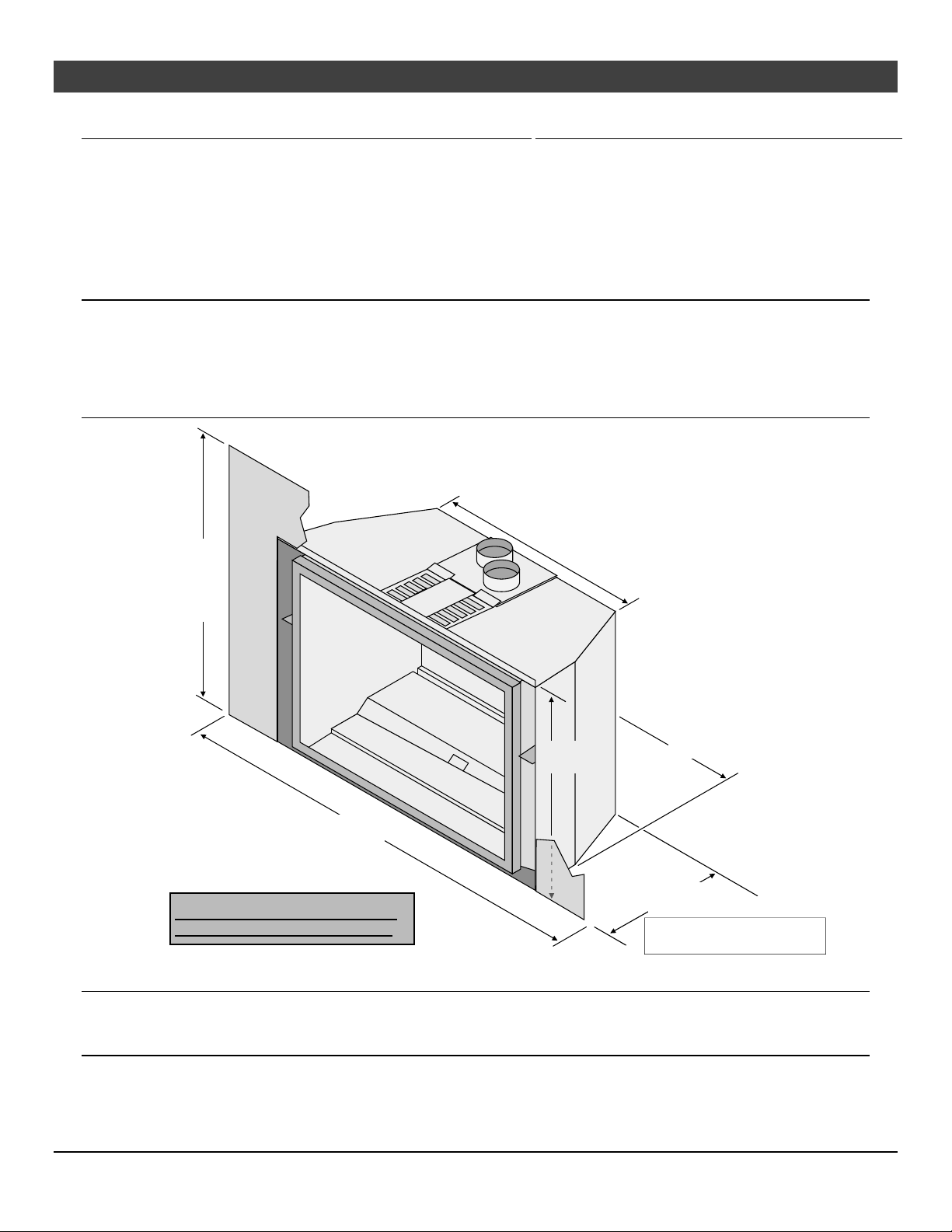
Dimensions
21" *
Small 25"
(63 5 mm)
(534mm) *
Large 28-1/2"
(72 4 mm)
19-1/2" *
(496mm) *
Small 38" (966mm)
Large 40" (1016mm)
* See "Fireplace Requirements"
for minimum fireplace sizing.
IDB1005
Electrical Specifications (for blowers)
Electrical Rating 120 Volts, 1.8 Amps, 60 Hz (205 watts) (typical max amps: 5).
Fuel
29-1/2" *
(750mm) *
15" *
(381mm) *
13-3/4"* if using panel trim.
(350mm) *
This heater is shipped in natural gas (NG) configuration but may be converted to propane (LP) using
the LP Conversion Kit (included) and the LP stepper motor (SKU 250-01463, sold separately). The
sticker on top of the gas control valve will verify the correct fuel.
© Travis Industries 1/11/2021 - 1521 430 EG GSR2
Page 7

Installation (for qualified installers only) 7
Installation Warnings
Failure to follow all of the requirements may result in property damage, bodily injury, or even death.
This heater must be installed by a qualified installer who has gone through a training program
for the installation of direct vent gas appliances.
The installation must conform with local codes or, in the absence of local codes, the National
Fuel Gas Code, ANSI Z223.1/NFPA 54, or the National Gas and Propane Installation Code, CSA
B149.1.
In Manufactured or Mobile Homes must conform with Manufactured Home Construction and
Safety Standard, Title 24 CFR, Part 3280, or, when such a standard is not applicable, the
Standard for Manufactured Home Installations, ANSI/NCSBCS A225.1. This appliance may be
installed in Manufactured Housing only after the home is site located.
The heater is designed to operate on natural gas, or propane (LP).
All exhaust gases must be vented outside the structure of the living area. Combustion air is
drawn from outside the living-area structure.
Notify your insurance company before hooking up this heater.
The requirements listed below are divided into sections. All requirements must be met
simultaneously. The order of installation is not rigid – the qualified installer should follow the
procedure best suited for the installation.
Packing List
Propane (LP) Conversion Kit
Remote Control
"Fireplace Altered" tag (attach to the fireplace)
46” Flex Line with Adapter and Shutoff Valve
Additional Items Required
Faceplate
3" Diameter Gas Liner with Termination (Kit – sku# 96200339)
Gas Line Equipment (shutoff valve, pipe, etc.)
Panel Kit
Fireback Kit
Media
If using LP (propane) a conversion kit is required (sku# 250-01463 – GSR Stepper Motor Kit).
Order of Installation
1. Run gas line to the fireplace.
2. Remove the glass frame.
3. Run vent through fireplace chimney. On larger fireplaces, the vent connector may be left in place. For
smaller fireplaces, remove the vent connector. See “Vent Connector Removal and Installation” for details.
4. Place insert into position and attach the gas line and vent.
5. Remove the burner.
NOTE: If using propane (LP), convert the appliance at this time.
6. Install the firebacks.
7. Replace the burner.
8. Install the media (logs, stones - see instructions included with the media).
9. Install the surround panel (see instructions included with surround panel).
10. Follow the instructions under “Finalizing the Installation.”
© Travis Industries 1/11/2021 - 1521 430 EG GSR2
Page 8
8 Installation (for qualified installers only)
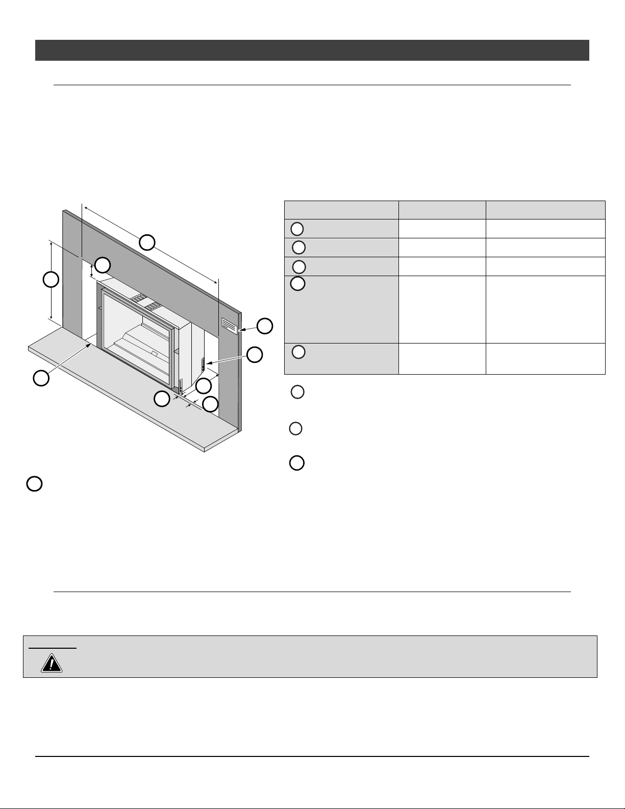
Fireplace Requirements
Insert must be placed within a code-conforming masonry fireplace or tested and listed factory-built
(metal) wood-burning fireplace. Repair any fireplace damage prior to installation.
Because the insert uses a circulation blower, clean the fireplace, smoke shelf, and chimney prior to
installation.
This heater may be placed in a bedroom. Please be aware of the large amount of heat this appliance
produces when determining a location.
Do not place insulation or any other material on top of the insert. This may block the upper accent
light ventilation, leading to premature bulb failure.
Fireplace Sizing 1-Piece Panel 1-Piece Panel w/ Trim
a
Minimum Height
b
g
a
I
h
f
e
I Attach the “This fireplace has been altered…” plate to the fireplace (use two screws or other suitable method). You may
wish to place it in a location where it will be covered by the surround panels.
c
d
b
Minimum Width
c
Minimum Depth
d
Minimum Hearth
Depth (see “Hearth
Requirements” on
the following page
for full details)
e
Extension onto
Hearth
The gas and electrical line should be installed prior to installing
f
the heater.
For tight fits (under 24”) see the section “Removing the Vent
g
Connector”.
See “Leveling Legs” for details on leveling the heater.
h
20-1/4” (515mm)
30-1/2” (775mm)
15-1/2” (394mm)
19-3/4” (502mm)
30-1/4” (768mm)
14-1/4” (357mm)
0” (0mm) 0” (0mm)
0” (0mm) 1-1/4”(32mm)
Fireplace Clearances to Gas Insert
Side of Insert to Inside of Fireplace ½” (13mm)
Back of Insert to Inside of Fireplace ½” (13mm)
Top of Insert to Inside of Fireplace 3/4” (20mm)
Masonry Fireplace Hearth Requirements
A panel trim kit is available for this appliance. When using the kit, the appliance will sit forward of the fireplace
opening 1-1/4” (32mm).
WARNING:Anon‐combustiblehearthisnotrequiredinfrontoftheappliance.However,iftheheaterisinstallednextto
thefloor,werecommendahearthtoprotecttheflooringsurfacefromdiscolorationorothernegativeimpacts
fromtheheater.
© Travis Industries 1/11/2021 - 1521 430 EG GSR2
Page 9
Installation (for qualified installers only) 9
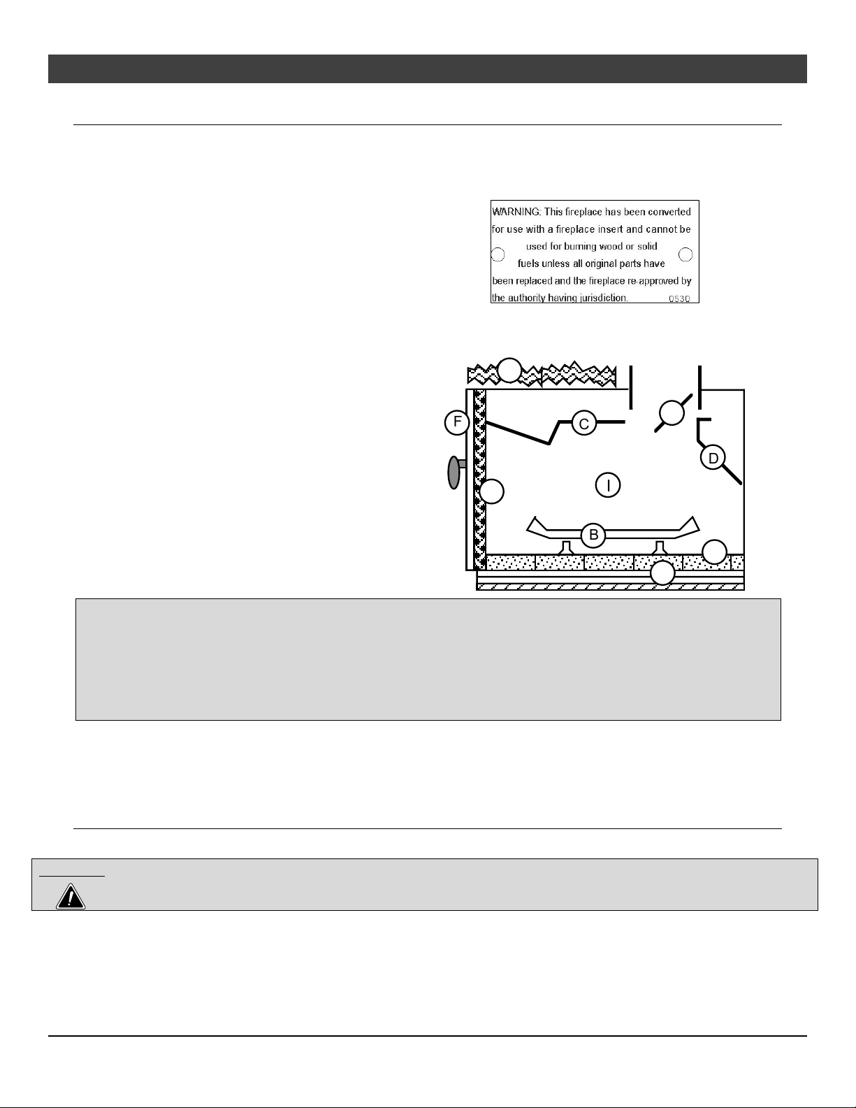
Factory-Built (Metal) Wood-Burning Fireplace Requirements
The damper ("A") and grate (with log set) ("B") must be removed (see the illustration below)
The smoke shelf ("C"), internal baffles ("D"), screen ("E"), masonry lining or refractory ("G" & "I"), and
metal or glass doors ("F") may be removed (if applicable)
The fireplace must be permanently marked to
indicate that it has been altered and is no longer
suitable for burning solid fuel (wood) unless the
removed parts are re-installed. Cutting of any
sheet metal parts is prohibited.
The metal floor (“J”) of the firebox may be removed
in certain cases*.
The insulation ("H"), and any structured rigid frame
members must not be removed or altered (side and
top of door frame, side, and top of the face of the
fireplace, metal sides, etc.).
H
F
E
C
I
A
D
B
G
J
*CAUTION – Removal of the firebox floor of a factory-built solid fuel fireplace in order to accommodate the
installation of a gas-fired fireplace insert is not covered under (ANSI Z21.88 – CSA 2.22 or ANSI Z21.50 – CSA
2.33) standard(s) used to certify the gas-fired fireplace insert or UL 127 and ULC S627 standards used to
certify solid fuel factory-built fireplaces. The Intertek safety certification will not apply to this installation method.
This installation method must be deemed acceptable by the Authority Having Jurisdiction (AHJ) prior to the gasfired fireplace insert being installed. The sheet metal base (or metal wrap) of the fireplace must be left in place
and a minimum ½” cement board sheet placed under the entire length and width of the appliance.
If the factory-built fireplace has no gas access hole(s) provided, an access hole of 1-1/2 inch (37.5 mm) or
less may be drilled through the lower sides or bottom of the firebox in proper workmanship like
manner. This access hole must be plugged with non-combustible insulation after the gas supply line has
been installed.
Factory Built Fireplace Hearth Requirements
½” of non-combustible material is required underneath the entire footprint of the insert.
WARNING:A non-combustible hearth is not required in front of the appliance. However, if the heater is installed next to the
floor, we recommend a hearth to protect the flooring surface from discoloration or other negative impacts from
the heater.
© Travis Industries 1/11/2021 - 1521 430 EG GSR2
Page 10
10 Installation (for qualified installers only)
(
)
)
Maxi
th
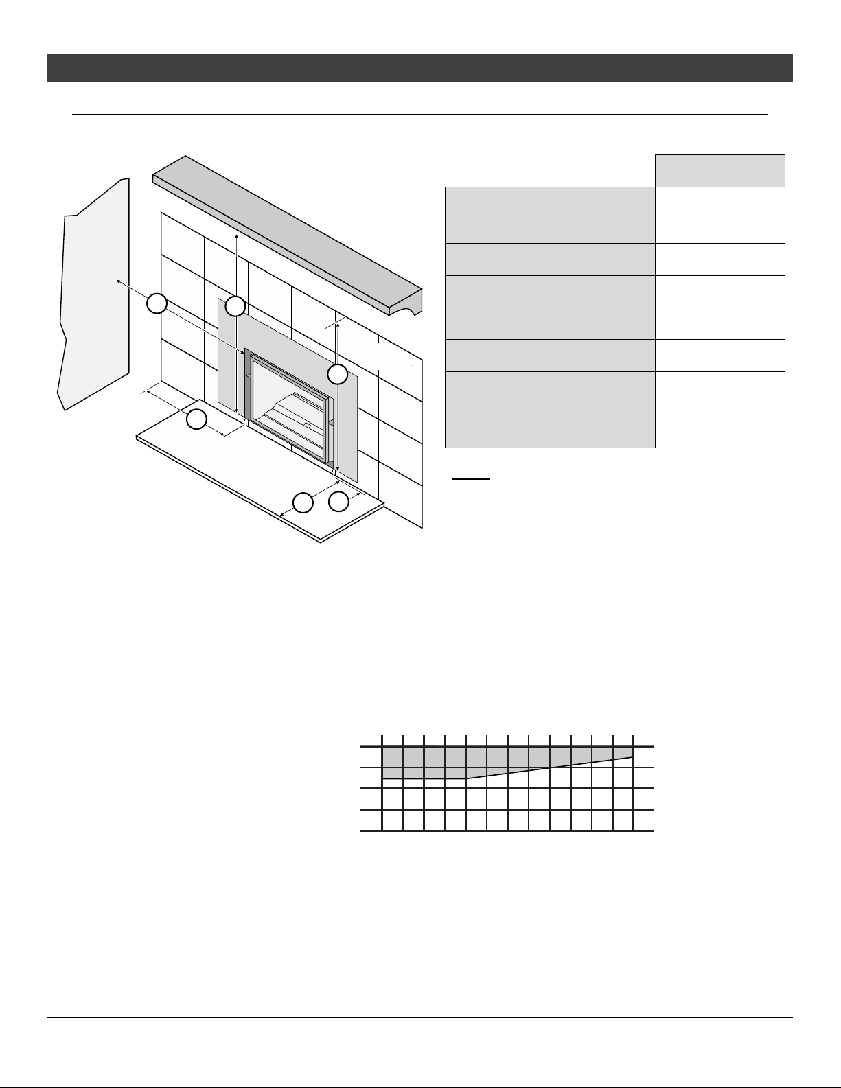
Clearances
Due to the high temperature of the heater, it should be located out of traffic and away from furniture and
draperies.
IDB1007
Side
Wall
k
C
o
m
b
u
s
t
i
b
l
e
o
r
N
o
n
-
C
o
m
b
u
C
o
m
n
s
t
i
b
l
e
b
u
s
t
i
b
M
a
n
t
l
e
T
o
p
e
l
F
a
c
i
n
g
No
n
-
C
o
m
b
F
u
a
s
c
t
i
i
n
b
g
l
m
e
k Sidewall to Insert
l Side Facing
(non-combustible)
m Top Facing*
(non-combustible)
n 12” Mantel* (combustible
or non-combustible)
n 4” Mantel* (combustible
or non-combustible)
p Hearth Extension to the
Front of Insert
x Extension onto Hearth
Minimum
Clearances
5" (127mm)
3-3/8 " (86mm)
32-3/8" (823mm)
34-1/2" (877mm)
33-1/2" (851mm)
0" (0mm)
1 Piece Panel
l
1 Piece Panel w/Trim Kit
1-1/4” (32mm)
* Measured from the base of the insert.
NOTE: the non-combustible top facing must extend
32-3/8” (823mm) above the base of the insert or to
p
x
the bottom of the mantel (whichever is less).
Mantel Clearances
The maximum mantel depth is 12” (305mm).
NOTE: The combustible area above the facing must not protrude more than 3/4" (20mm) from the facing.
If it does, it is considered a mantel and must meet the mantel requirements listed in this manual.
mum Mantel Dep
)
)
)
)
)
m
m
m
6
2
(
"
"
"
0
2
1
m
m
m
1
7
5
(
0
7
1
(
(
"
"
3
4
35"+(889mm+)
antel Height
Above Base
of Fireplace
34"(864mm)
33"(839mm)
32"(813mm)
788mm
31"
)
m
m
2
2
1
(
"
5
)
)
m
m
7
(
"
6
m
m
m
m
8
3
0
7
5
2
1
1
(
(
"
"
7
8
)
)
)
m
m
4
2
(
"
9
m
m
m
m
4
9
5
2
2
(
"
"
1
0
1
1
m
m
m
m
5
0
0
8
3
2
(
(
"
2
1
0" (0mm)
© Travis Industries 1/11/2021 - 1521 430 EG GSR2
Page 11
Installation (for qualified installers only) 11
Televisions Placed Above the Insert
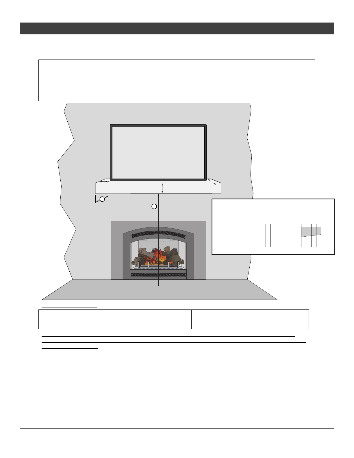
The following section gives guidelines to place a television above the insert.
IMPORTANT NOTE REGARDING TELEVISIONS AND THIS INSERT
Most television manufacturers instruct the homeowner not to place the television above a heat source like this insert.
Doing so may decrease the longevity of the television and negate the warranty. If you do place a television above the
insert, you should place a mantel between the insert and television. Follow the guidelines below to reduce the
amount of heat reaching the television. Travis Industries does not take responsibility for any negative impact on
televisions placed near this insert.
Television (TV)
Min. 1" (26mm)
Min. 2" (51mm)
Min. 1" (152mm)
b
a
(a)
Heig ht
36"+(915mm+)
Above
Base of
Fireplace
(4) AA Batteries
F
U
S
E
TOP
F
E
U
S
S
U
E
F
35"(889mm)
34"(864mm)
(
"
"
0
1
(b) Depth
)
)
)
m
)
1
(
m
2
0
"
5
430 EG
)
m
m
2
1
(
m
m
m
m
m
m
m
7
3
8
2
0
5
7
2
1
1
(
(
(
(
"
"
"
"
8
9
6
7
)
)
m
m
m
m
m
1
6
5
5
7
2
(
(
"
"
"
2
3
4
Minimum Dimensions:
(a) Minimum Mantel Height above Base of Insert* 34” (864mm) with 8” (204mm) mantel depth
(b) Minimum Mantel Depth* 8” (204mm)*
* Minimum mantel depth must be 8”(204mm) to allow heat to dissipate. If using a mantel larger than 8”
(204mm), make sure to adjust the mantel height (a) to meet the mantel clearance (see mantel requirements
on page 10 for details).
The mantel must extend 2” in front of the television and 1” to both sides.
If you have a television that is greater than 6” deep (including the 1” gap behind), you will need to alter the
mantel depth and height (see the example below).
The television must have a 1” gap to the wall to allow for proper cooling.
WIRING NOTE: If running wiring into the enclosure, use thermal insulating wrap around the wiring. Secure the wiring
to protect from contact with hot surfaces.
)
)
)
m
m
9
2
2
"
0
1
)
)
m
m
m
m
m
m
9
4
5
7
5
0
2
2
3
(
(
(
"
"
1
2
1
1
© Travis Industries 1/11/2021 - 1521 430 EG GSR2
Page 12
12
Installation (for qualified installers only)
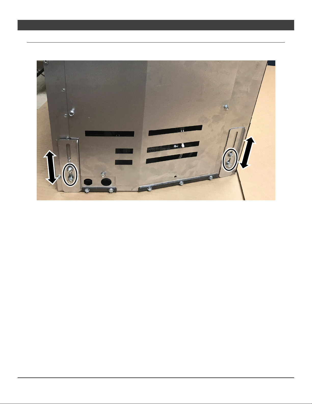
Leveling Bolts
This heater includes front and rear leveling legs to accommodate fireplaces with a step-down firebox.
Loosen the (4) bolts and adjust the legs down until the insert is properly supported and level.
© Travis Industries 1/11/2021 - 1521 430 EG GSR2
Page 13
Installation (for qualified installers only) 13
Electrical Requirements
Travis Industries manufactures a wiring kit specifically for inserts (sku 97200315). This kit allows installers to
wire 120 volt AC power into a fireplace directly to the insert, eliminating the need for an external power cord.
Plug the power cord into a grounded 120 Volt outlet (do not remove the grounding pin).
The appliance, when installed, must be electrically grounded in accordance with local codes or, in the
absence of local codes, with the National Electrical Code, ANSI/NFPA 70, or the Canadian Electrical
Code, CSA C22.1.
Do not route the power over the appliance or near any hot or moving components.
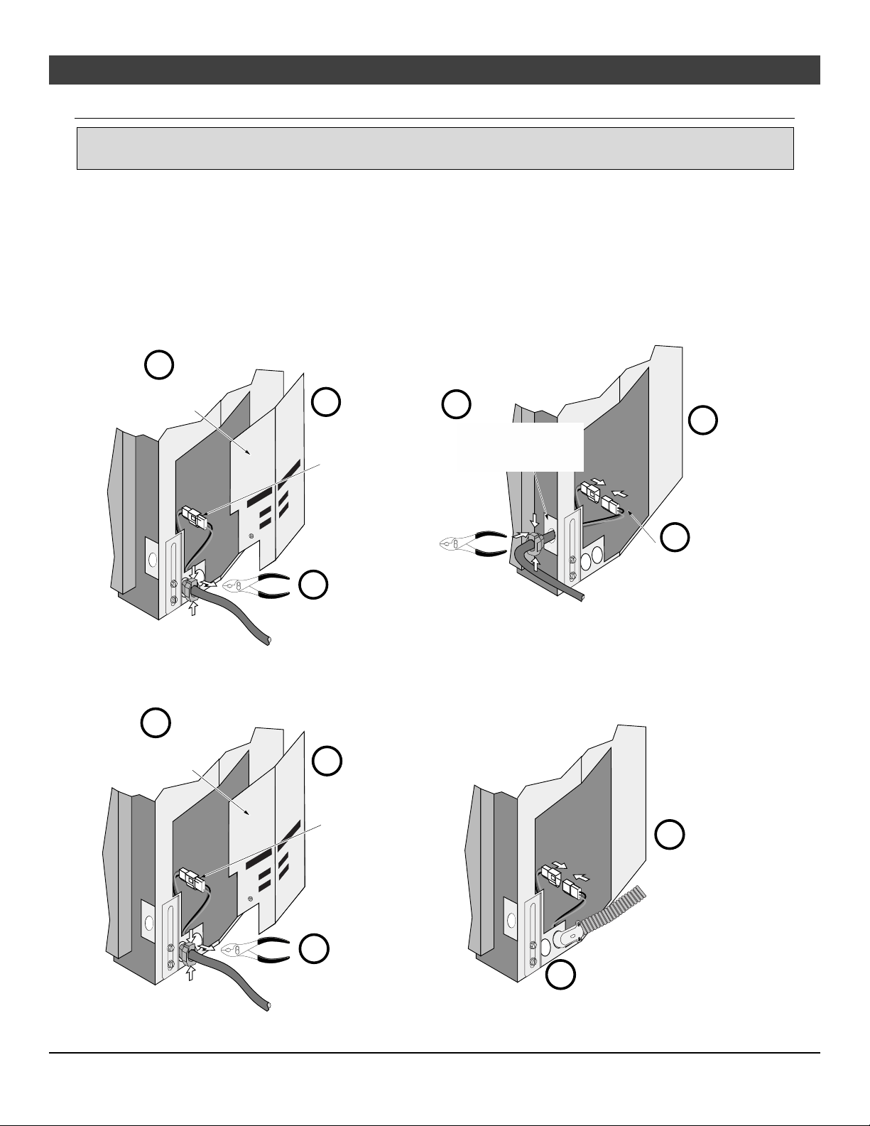
Re-Routing the Power Cord to the Front of the Insert
The power cord is shipped attached to the side of the insert. It may be routed to the front where it exits
behind the face but in front of the surround panel. See the directions below for details.
a
Remove the side
access panel.
c
Disconnect the
molex connection
and remove the
power cord.
d
Route wires through the
front mounting bracket.
Use pliers to reinstall the
strain relief.
d
Reinstall the
access panel
a
b
Use pliers to remove
the strain relief.
Using the Insert Wiring Kit
See the instructions included with the wiring kit for attaching the kit to the side of the insert.
a
Remove the side
access panel.
c
Disconnect the
molex connection
and remove the
power cord.
a
e
Reconnect the
molex connection.
e
Reconnect the Molex connector
and replace the access panel.
b
Use pliers to remove
the strain relief.
© Travis Industries 1/11/2021 - 1521 430 EG GSR2
d
Attach the hard wire kit to
insert (see kit instructions for details).
Page 14
14
Installation (for qualified installers only)
Gas Line Requirements
MASSACHUSETTS INSTALLATIONS - WARNING:
THIS PRODUCT MUST BE INSTALLED BY A LICENSED PLUMBER OR GAS FITTER WHEN INSTALLED WITHIN THE
COMMONWEALTH OF MASSACHUSETTS.
OTHER MASSACHUSETTS CODE REQUIREMENTS:
Flexible connector must not be longer than 36 inches.
Shutoff valve must be a “T” handle gas cock.
Only direct vent sealed combustion products are approved for bedrooms or bathrooms.
Fireplace dampers must be removed or welded in the open position prior to the installation of a fireplace insert or gas log.
A carbon monoxide (CO) detector is required in the same room as the appliance.
The gas line must be installed in accordance with all local codes if any; if not, follow ANSI 223.1 and
the requirements listed below.
A manual shutoff valve is required within 3’ of the heater. It should be placed upstream of the flex line
(if used) and may be installed behind the access door inside the heater.
The heater and gas control valve must be disconnected from the gas supply piping during any
pressure testing of that system at test pressures in excess of 1/2 psig. For pressures under 1/2 psig,
isolate the gas supply piping by closing the manual shutoff valve.
Leak test all gas line joints and the gas control valve prior to and after starting the heater.
This heater is designed either for natural gas or for propane (but not for both). Check the sticker on
the top of the gas control valve to make sure the correct fuel is used (see illustration on page 4).
Installation must be performed by a qualified installer, service agency, or the gas supplier (In
Massachusetts a licensed plumber/gas-fitter).
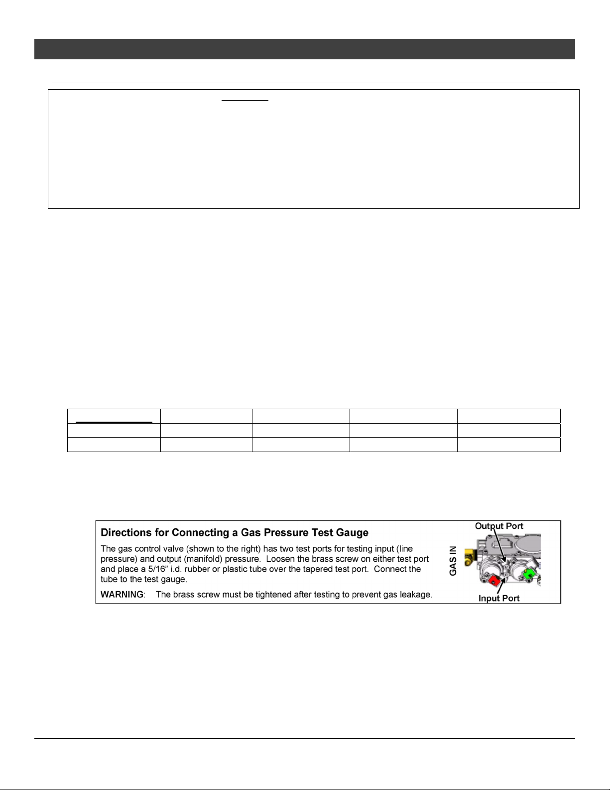
Gas Inlet Pressure
Gas Pressure
Natural Gas
Propane
If the pressure is not sufficient, make sure the piping used is large enough, the supply regulator is
adequately adjusted, and the total gas load for the residence does not exceed the amount supplied.
The supply regulator (the regulator that attaches directly to the residence inlet or to the propane tank)
should supply gas at the suggested input pressure listed above. Contact the local gas supplier if the
regulator is at an improper pressure.
Max. Input Pressure Min. Input Pressure Max. Manifold Pressure Min. Manifold Pressure
7" W.C. (1.74 kPA) 5.5” W.C. (1.37 kPA) 3.5” W.C. (0.87 kPA) 1.6” W.C. (0.40 kPA)
13" W.C. (3.23 kPA) 11” W.C. (2.74 kPA) 11” W.C. (2.74 kPA) 2.9” W.C. (0.72 kPA)
© Travis Industries 1/11/2021 - 1521 430 EG GSR2
Page 15
Installation (for qualified installers only) 15
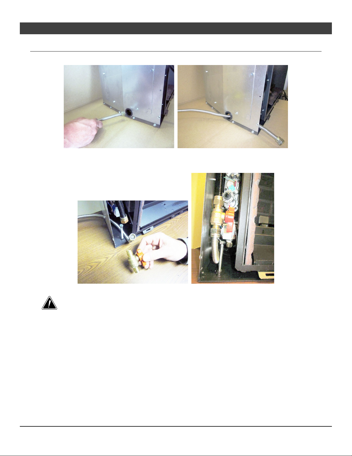
Gas Line Installation
1. Route the included flex tube through the hole in the left side of the insert and out the front as shown below.
2. Bend the flex tube up.
3. Attach the included gas shutoff valve to the end of the flex tube and gas inlet as shown below.
Position so the valve handle is on the right as shown.
Leak-test all gas line connections.
© Travis Industries 1/11/2021 - 1521 430 EG GSR2
Page 16
16 Installation (for qualified installers only)
Vent Requirements
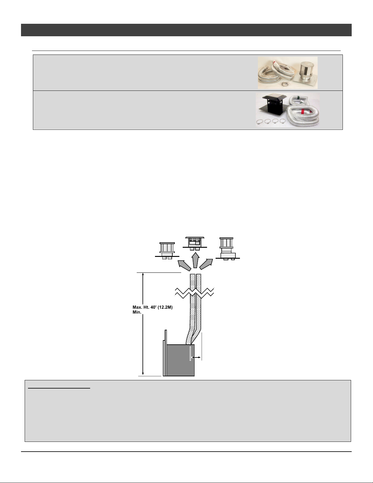
Travis Industries manufactures a vent kit specifically for this insert (sku
96200339). It includes 30’ (10M) of vent, hose clamps, and a high wind
cap. The flashing on the cap is 18” (458mm) by 18” (458mm).
Travis Industries manufactures a vent kit specifically for this insert (sku
96200330). It includes 30’ (10M) of vent, hose clamps, and a prairie
cap. The flashing on the cap is 18” (458mm) by 18” (458mm).
The gas appliance and vent system must be vented directly to the outside of the building, and never be attached to
a chimney serving a separate solid fuel or gas-burning appliance. Each direct vent gas appliance must use its own
separate vent system.
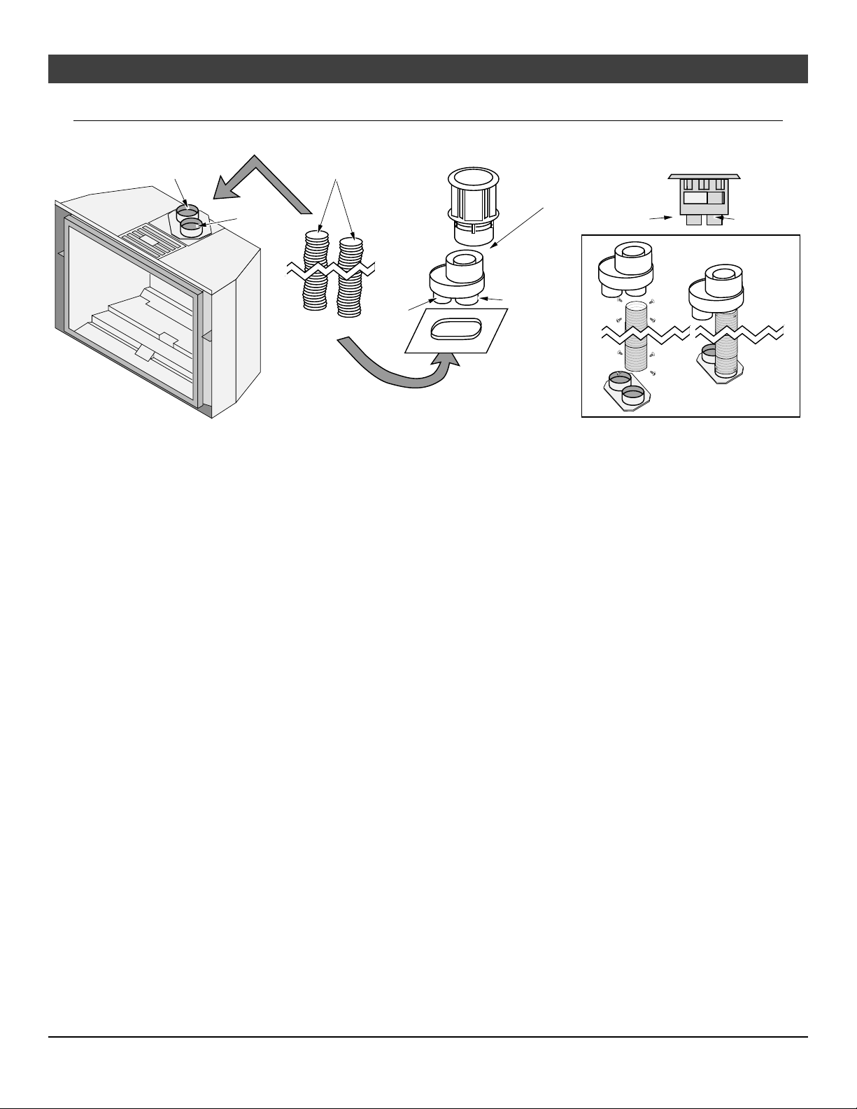
Make sure the exhaust pipe on the heater connects to the exhaust portion of the cap. The illustrations below show
how the flex liners should be attached.
The exhaust vent must reline the entire length of the chimney and terminate above the chimney top.
Be careful not to crimp or rupture the liner when bending it into chimney offsets.
When installed, the vent must meet all of the vent manufacturer's requirements.
Use the following vent:
3” UL 441 or 1777 Gas Liner for Exhaust, 3” UL 441 or 1777 Gas Liner for Air Inlet
Duravent 6-5/8” to 3” Co-Linear Adapter and Flashing (46DVA-Gk)
Duravent High-Wind Vertical Termination (46DVA-VCH) for high-wind applications or Prairie Cap
Max. Ht. 40' (12.2M)
Min. Ht. 16' (5M)
Max. 4'
(1.2M)
offset
Drafting Performance
This direct vent appliance requires natural draft to operate (similar to a wood stove or other heating appliance). Draft
can be adjusted using the included restrictor. The restrictor settings detailed in the manual should be followed
(variations may occur depending upon installation parameters).
Many factors may negatively influence the draft of the appliance. Travis Industries will not be responsible for improper
draft due to factors such as trees, hills, buildings, obstructions, excessive wind, extreme hot or cold outdoor
temperatures, restrictive vent terminations, or influence from mechanical systems.
© Travis Industries 1/11/2021 - 1521 430 EG GSR2
Page 17
Finalizing the Installation 17
Vent Installation
Secure the vent to the insert and termination kit using screws.
Inlet (3" 76mm)
3" (76mm) dia. Gas Liner
Approved
Cap
Exhaust
(3" 76mm)
Inlet
Additional Coaxial
Sections May Be Added
(support as needed)
Exhaust
For optimum performance, keep the vent as straight as possible (no 90 bends).
Inlet Exhaust
© Travis Industries 1/11/2021 - 1521 430 EG GSR2
Page 18
18 Finalizing the Installation
Vent Location
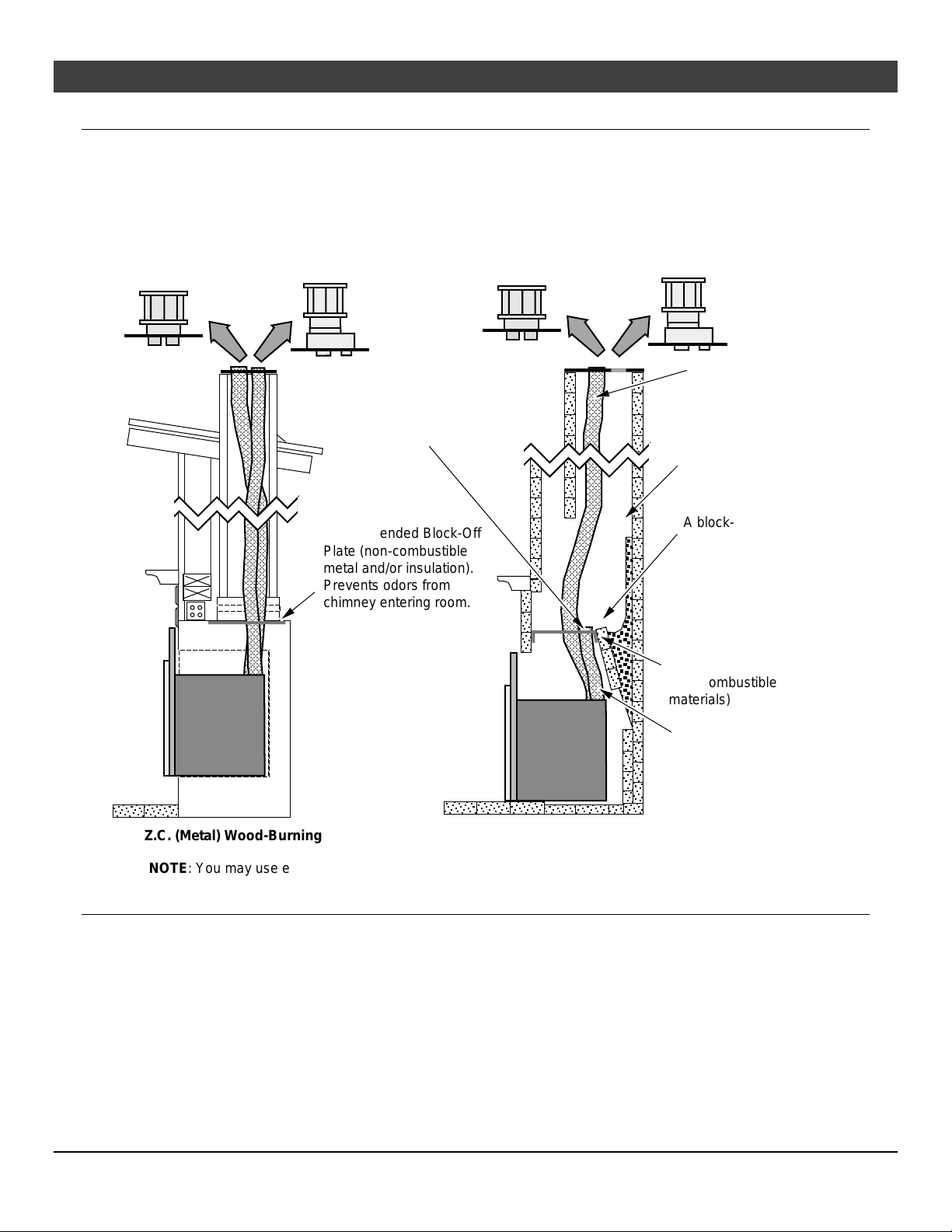
An Exhaust Restrictor is built into the appliance to adjust the flow rate of exhaust gases. This
ensures proper combustion for all vent configurations. Depending upon the vent configuration, you
may be required to adjust the restrictor position. See “Exhaust Restrictor Settings” on page 21.
Vent Configurations
Inlet & Exhaust Re-Line
Recommended Block-Off
Plate (non-combustible
metal and/or insulation).
Prevents odors from
chimney entering room.
Inlet
Exhaust Only Re-Line
Exhaust
Any cracks or
damage inside the
chimney must be
repaired.
A block-off plate must
seal the intake to the
chimney space. This
way air is drawn down
the chimney for
combustion air.
Block-Off Plate
(non-combustible
materials)
Inlet
Z.C. (Metal) Wood-Burning Fireplace
NOTE: You may use either re-line configuration with a masonry or zero-clearance fireplace.
Masonry Fireplace
Altitude Considerations
This heater has been tested at altitudes ranging from sea level to 6,000 feet (1,800 M). In this
testing, we have found that the heater, with its standard orifice, burns correctly with just an air shutter
adjustment.
Failure to adjust the air shutter properly may lead to improper combustion which can create a safety
hazard. Consult your dealer or installer if you suspect an improperly adjusted air shutter.
© Travis Industries 1/11/2021 - 1521 430 EG GSR2
Page 19
Finalizing the Installation 19
R
Vent Attachment – Tight Installations
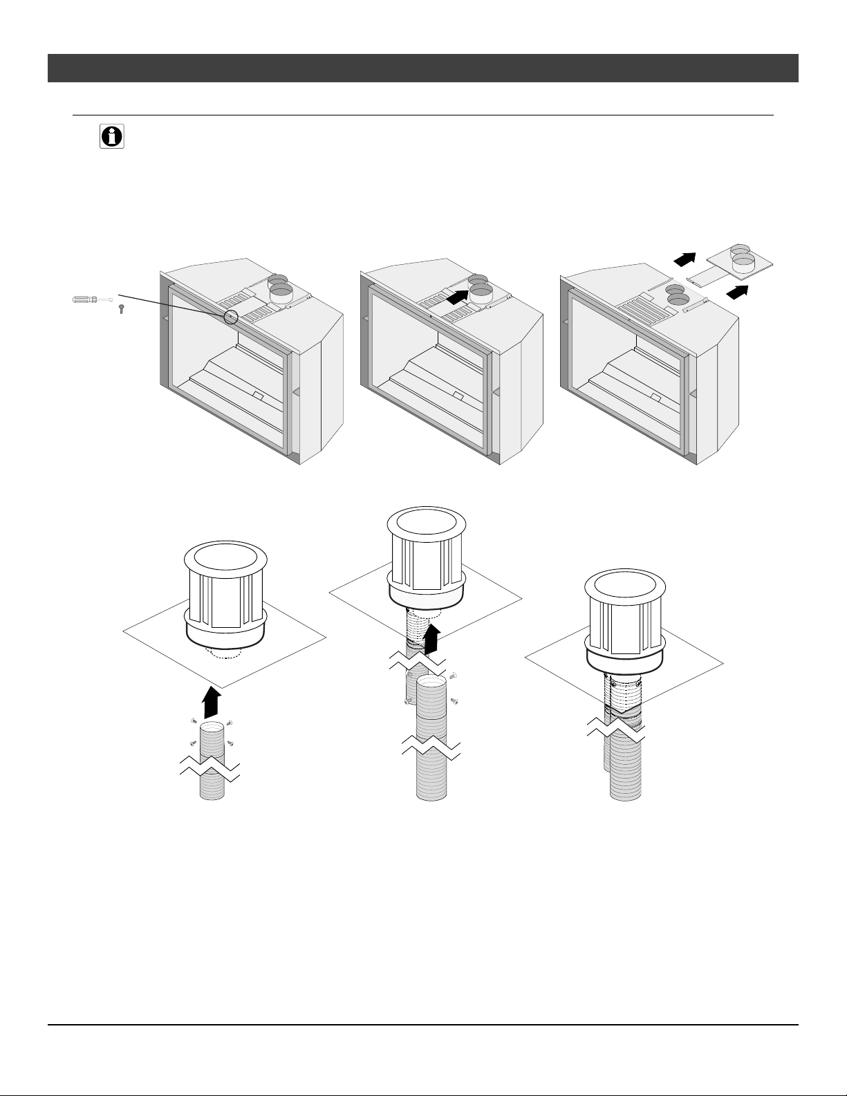
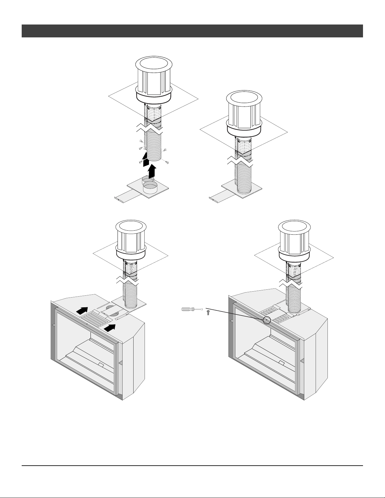
The vent connector is shipped attached to the insert but must be removed to facilitate tight
installations. See the directions below for installation.
1. Locate the screw in the top-center of the front of the insert. Use a ¼” nut driver to remove the screw
and slide the connector toward the back of the insert to disengage the connector from the top of the
insert.
emove Screw
1/4" Nutdriver
2. Stretch the liners to their full length. Attach the flex liners to the cap (secure with screws). Route the
flex vent through the chimney from above.
© Travis Industries 1/11/2021 - 1521 430 EG GSR2
Page 20
20 Finalizing the Installation
w
3. Pull the liners straight and cut to length (height of the insert). Attach the bottom of the flex liners to the
connector, removed in step 1.
4. Slide the insert into place while guiding the vent connector into the guides on top of the insert. Secure
the vent connector to the appliance using the screw removed in step 1.
e-install Scre
1/4" Nutdriver
© Travis Industries 1/11/2021 - 1521 430 EG GSR2
Page 21
Finalizing the Installation 21
40 Feet
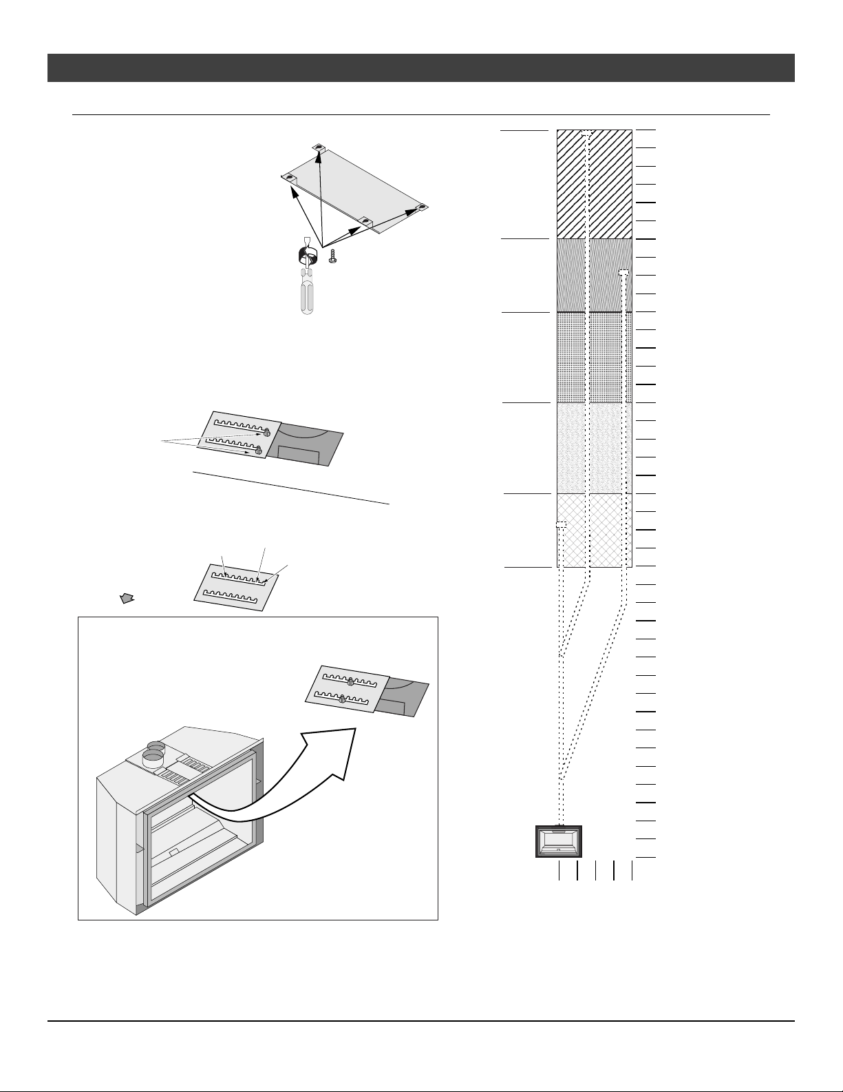
Exhaust Restrictor Settings
(max.)
Use a 1/4” nut driver to loosen
the screws that secure the baffle
to the top of the firebox. Slide
the baffle slightly forward until
the screw heads are in line with
the keyhole slots . Lower the
baffle and remove from the
firebox. (Re-install baffle after
the restrictor has been
adjusted).
1/4" Nutdriver
Slide the restrictor to the correct position (consult the vent
chart to the right to determine the proper setting for your
installation). The screw location indicates the restrictor
position.
Loosen these
2 screws on the
exhaust restrictor.
Back of Firebox
# 7...
B
a
c
k
W
a
# 2...
#1 (open - stock position)
F
i
r
e
b
o
x
R
o
l
l
o
f
F
i
r
e
b
o
x
o
f
Position #7
Position #6
Position #5
Position #3
Position #1
(Stock)
35 Feet
30 Feet
25 Feet
20 Feet
16 Feet (Min.)
15 Feet
In this example, the restrictor is set in the #5 position.
Tighten the screws to secure the restrictor.
10 Feet
5 Feet
0 Feet
0 Feet
2 Feet
4 Feet
(max.)
© Travis Industries 1/11/2021 - 1521 430 EG GSR2
Page 22
22 Finalizing the Installation
Horizontal Termination
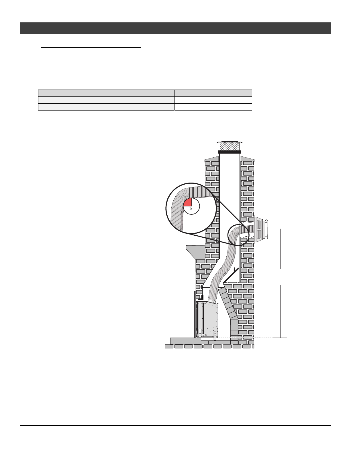
DuraVent manufactures a vent kit for horizontal that allows for terminating horizontally when installed in a
masonry fireplace (not for use with ZC fireplaces). The DuraVent kit (46DVA-HCL33 and 46DVA HCL34)
is approved for use with Travis Industries gas inserts.
These kits can be purchased from your Travis Industries dealer.
Application DuraVent Part #
For inserts that use 3” exhaust and 3” intake 46DVA-HCL33
For inserts that use 4” exhaust and 3” intake 46DVA-HCL34
Refer to the kit manufacturer’s instructions for details and requirements for installation. In addition to the
manufacturer’s requirements, the following requirements must be met:
The termination center MUST be
a minimum of 5’ from the base of
insert.
The termination center MUST
NOT be more than 8’ from the
base of the insert.
The radius of any bends in the
flexible venting MUST NOT be
less than a 4” radius
All portions of the venting MUST
have at least a 1/4” rise per 12” of
horizontal run
r 4”
Radius
4” Min
Min. 5’
Max. 8’
© Travis Industries 1/11/2021 - 1521 430 EG GSR2
Page 23
Finalizing the Installation 23
’
Co-Linear to Co-Axial Pipe
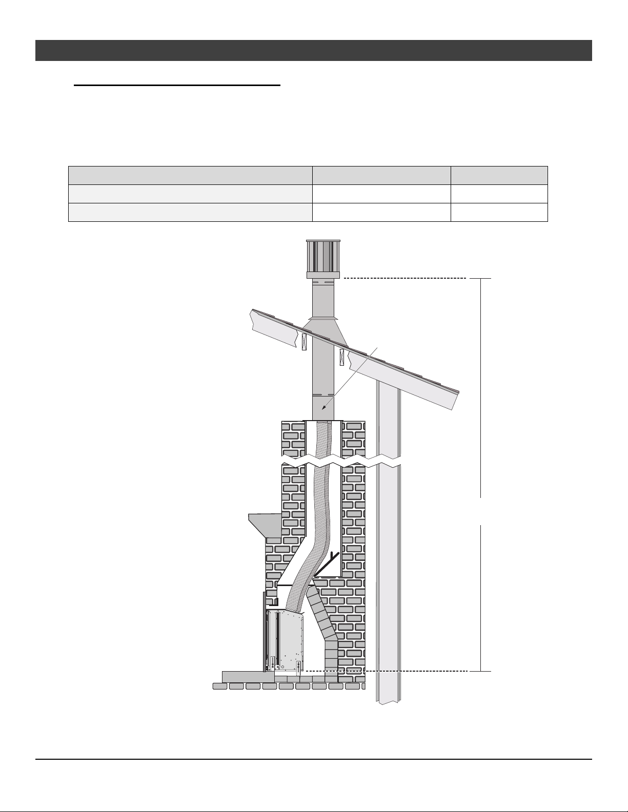
DuraVent manufactures a vent kit that adapts flexible co-linear venting to co-axial pipe. This can be
helpful for situations such as when a damaged masonry chimney top is removed to below the roofline or
when an additional story is added to a home and the added height covers the existing masonry chimney
height. The DuraVent kits (46DVA-CLTA and 46DVA-34CLTA) are approved for use with Travis
Industries gas inserts.
These kits can be purchased from your DuraVent dealer.
Application DuraVent Part # DuraVent Stock #
For inserts that use 3” exhaust and 3” intake 46DVA-CLTA 810014742
For inserts that use 4” exhaust and 3” intake 46DVA-34CLTA 810014340
- Check with the local
Authority Having
Jurisdiction before
installing in this manner.
- The fireplace must be
permanently marked to
indicate that it has been
altered and no longer
suitable for burning solid
fuel (wood).
- All additional
requirements in the
manual for the installation
must be met.
- Refer to the vent
manufacturer’s
instructions for further
details.
DuraVent Co-Linear
to Co-Axial Adapter
Max. 40
(12.2M)
© Travis Industries 1/11/2021 - 1521 430 EG GSR2
Page 24
24 Finalizing the Installation
Glass Frame Removal and Installation
A barrier designed to reduce the risk of burns from the hot viewing glass is provided with this
appliance and shall be installed for the protection of children and other at-risk individuals.
If the barrier becomes damaged, the barrier shall be replaced with the manufacturer’s barrier for
this appliance.
The appliance must be completely cool before removing the glass.
Do not strike or slam the glass.
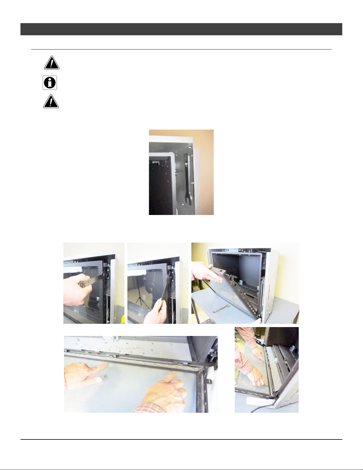
1. The glass removal tool is located at the upper right of the convection area and may be removed with a ¼”
nut driver.
NOTE: Replace the tool in this location after removing the glass frame.
2. Remove the glass frame as shown below. The glass frame is held in place with three tabs inserted
into three slots at the bottom of the insert.
© Travis Industries 1/11/2021 - 1521 430 EG GSR2
Page 25
Finalizing the Installation 25
Steps for Finalizing the Installation
1. Remove the glass (see page 21).
NOTE: If using propane (LP) convert the appliance prior to installing the media.
2. We recommend you purge the gas line at this time (with the glass removed). This allows gas to be
detected once it enters the firebox, ensuring gas does not build up.
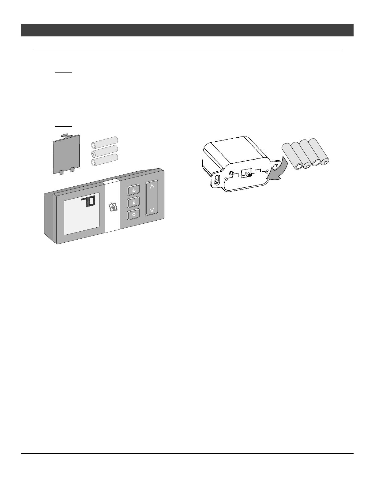
3. Install the four AA batteries (see illustration below). The AA batteries act as a power backup in case
the household (AC) power goes out and are required for operation. Install three AAA batteries into
the remote (see illustration below). Synchronize the transmitter to the IFC (see page 29).
4. Make sure the accent light bulbs are in place and work correctly.
NOTE: Take care to not touch the bulb with your fingers – use a cloth or paper towel).
AA Battery
AA Battery
AAA Battery
AAA Battery
AAA Battery
°F
AA Battery
AA Battery
5. Install the media (see the instructions included with the media kit).
6. Replace the glass.
7. Start the heater.
8. Leak test all gas joints.
9. Adjust the air shutter following the directions on the next page.
10. Attach the face following the directions included with the face.
11. Adjust the flame to its highest position - the flames should not contact the top of the firebox. Check the flame
on low position. The flames should burn off of each burner hole. If the heater does not work correctly,
contact your Travis dealer for a remedy.
12. Give this manual to the homeowner for future reference and fully explain the operation of this heater.
© Travis Industries 1/11/2021 - 1521 430 EG GSR2
Page 26
26
Finalizing the Installation
Air Shutter Adjustment
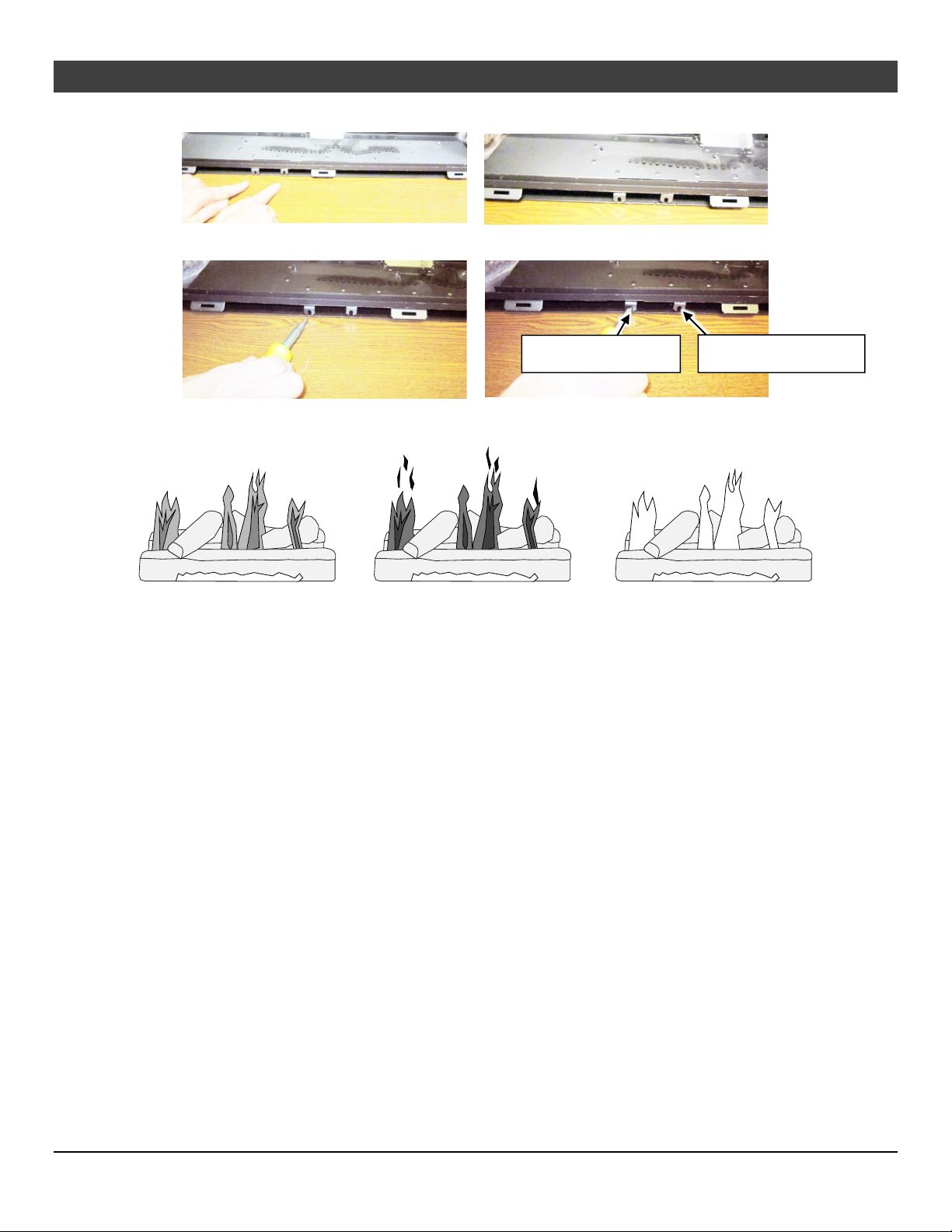
Left = More Air
Rear air shutter (gold)
Front air shutter (red)
Let the heater burn for fifteen minutes (make sure the media and glass are in place). The flames should
be yellow with no sooting. Adjust the air shutter, if necessary, to achieve the correct looking flame.
Correct
Flames should be blue at the
base, yellow-orange on the top.
If the flames are too tall or sooty on the
ends, open the air shutter.
Not Enough Air
Too Much Air
If the flames are all blue and
short, close the air shutter.
© Travis Industries 1/11/2021 - 1521 430 EG GSR2
Page 27
Finalizing the Installation
27
Burner Removal
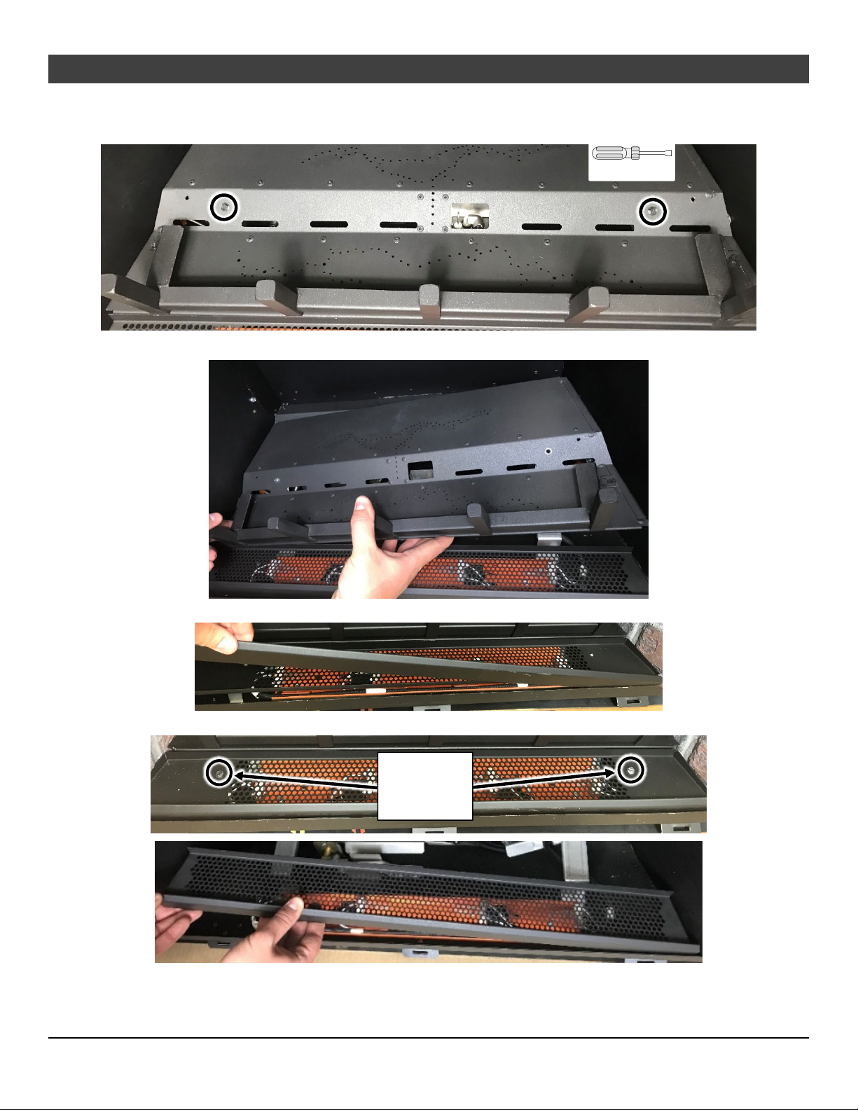
1. Remove the (2) burner attachment screws
1/4" Nutdriver
2. Lift the burner and grate assembly out of the firebox.
3. Lift the media tray skirt upward and remove it from the firebox.
4. Remove the (2) media tray attachment screws and lift the media tray up and out of the firebox.
Remove (2)
Media Tray
Screws
5. Install the firebacks. See the firebacks installation instructions for details.
6. Reverse the previous steps to replace the burner and grate assembly.
© Travis Industries 1/11/2021 - 1521 430 EG GSR2
Page 28
28 Operation
Before You Begin
Read this entire manual before you use your new heater (especially the section "Safety Precautions"
on pages 4 & 5). Failure to follow the instructions may result in property damage, bodily injury, or
even death.
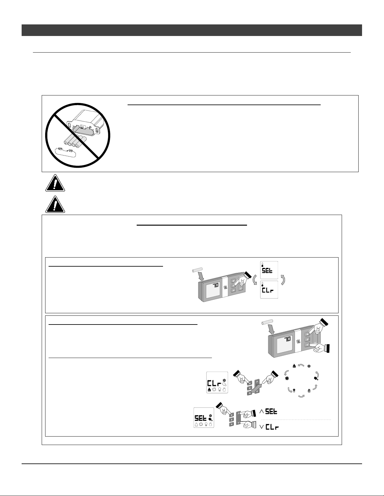
Remote Control Warnings
KEEP BATTERIES AND COVER INSTALLED AT ALL TIMES
The remote control system requires the batteries and battery cover to remain in
place at all times. Once the batteries or cover are removed, the system may re-start
in standing pilot mode. If this occurs when the heater is in Remote Mode, you will
not be able to turn the heater off manually from the battery box.
If you need to replace dead batteries, make sure to turn the appliance off before
removing the batteries.
NOTE: If the batteries go dead, the system will operate normally as long as
The transmitter and IFC are radio frequency devices. Placing the transmitter in or near metal may
severely reduce the signal range.
Turn off the main gas supply to the appliance during installation or maintenance. In case of remote
control malfunction turn off the main gas supply to the appliance.
household power (120v AC) is present.
PROGRAMMING THE REMOTE
The SIT GSR2 remote may be programmed to disable the thermostat or any of the modes (flame height, blower,
light, comfort control, Standing Pilot *, or auxiliary power input). This allows you to tailor the remote to the appliance.
* We do not recommend disabling the standing pilot option for our gas appliances. This feature may be
recommended for cold regions or installations with sub-optimal venting.
How to Disable/Enable the Thermostat
The remote is shipped with the thermostat enabled.
1 Remove one battery from the remote.
2 Press and hold the thermostat button while
replacing the battery. This will toggle the
thermostat function. Repeat this process to toggle
the thermostat function to the desired setting.
AAA Battery
°F
How to Disable/Enable Modes (Light, Blower, etc.)
The remote is shipped with all modes enabled.
1 Remove one battery from the remote.
2 Press and hold the on/off button and mode button while replacing the battery.
Keep the on/off button depressed during the following steps.
3 While keeping the on/off button depressed, press
and release the mode button until the mode that
needs to be changed is illuminated.
4 With the desired mode illuminated (see illustration
to the right), press the “up” or “down” button to
activate or clear the mode being addressed.
Make sure to keep the on/off button depressed
during this process.
5 Release the on/off button to complete
programming.
AAA Battery
"SET" = thermostat
function enabled.
"CLR" = thermostat
function disabled.
°F
Standing
Flame
Pilot
Height
Optional
Blower
Accent
Light
Comfort
Control
AUX
"SET" = selected
mode enabled.
"CLR" = selected
mode disabled.
© Travis Industries 1/11/2021 - 1521 430 EG GSR2
Page 29
Operation 29
Remote Set-Up
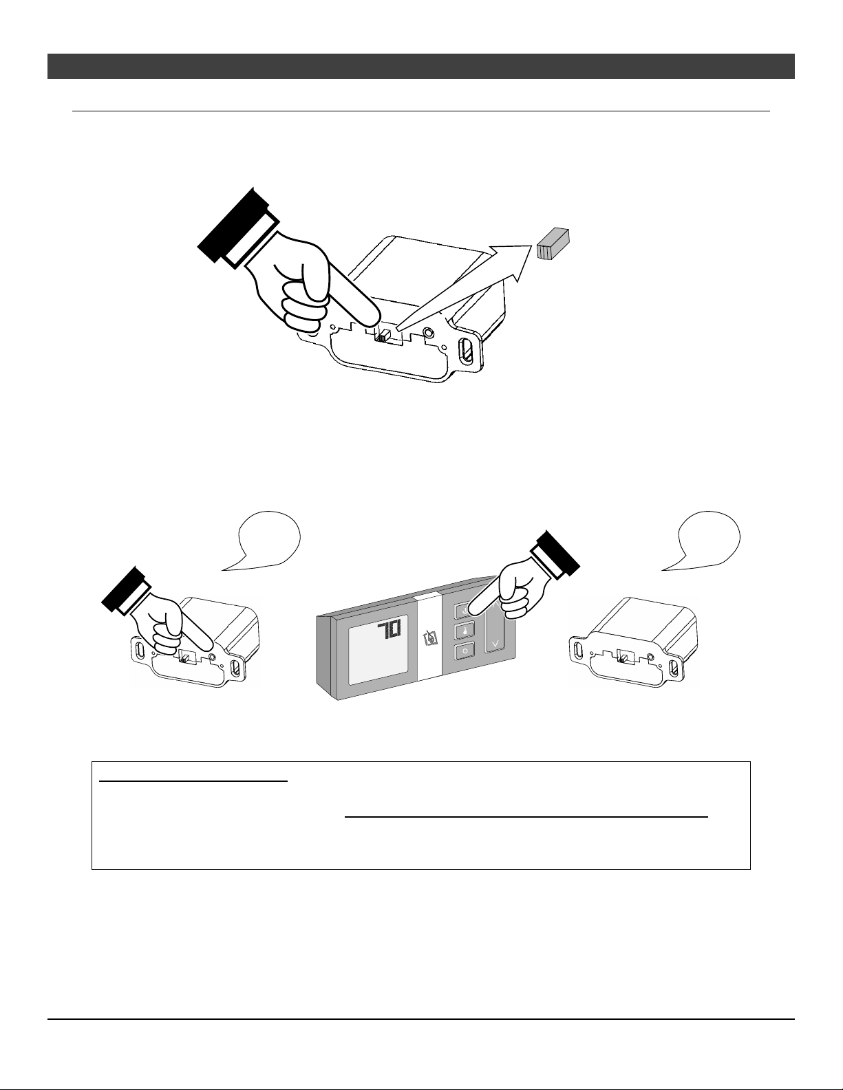
Verify the Switch is on “REMOTE”
The battery holder has a switch built into it (see Figure 1). This switch must remain in the REMOTE
position for the remote to operate.
ON REMOTE OFF
Figure 1
Synchronize the Transmitter to the IFC
The transmitter will need to be synchronized to the IFC (Integrated Fireplace Control) before the remote
will work correctly. Synchronizing is done in the following two steps below (see Figure 2):
1. Press the PRG (Program) button on the battery box (IFC will beep 3 times).
2. Press the “ON” button on the transmitter (IFC will beep 3 times).
"Beep"
"Beep"
"Beep"
°F
Figure 2
"Beep"
"Beep"
"Beep"
NOTE: If power is cut off to the IFC for an extended period of time, you may need to resynchronize the remote.
Clearing the System Memory
This appliance uses an Integrated Fireplace Control (IFC) to store the unique code for the remote control.
If you wish to clear the system memory, MAKE SURE GAS IS TURNED OFF TO THE APPLIANCE then
press the PRG (Program) button for 10 seconds. The pilot will start to spark repeatedly, signifying all
system memory has been cleared. The system will return to its original configuration: a remote will need
to be synchronized; and, the system will operate under continuous pilot mode.
© Travis Industries 1/11/2021 - 1521 430 EG GSR2
Page 30
30 Operation
Starting the Heater for the First Time
Burn the heater at a high setting with the blower off for an extended period (up to 48 hours). This will
cure the painted surfaces. Fumes from the paint curing and oil burning off the steel will occur. This
is normal. We recommend opening a window to vent the room.
Condensation may appear on the glass each time you start the heater - this is normal.
Blue Flames will occur on the heater when it first comes on. After fifteen minutes the flames will turn
a more realistic yellow and orange color.
Verify the batteries are installed (see page Error! Bookmark not defined.).
Location of Controls
Most features will be
controlled by the
included remote.
°F
Direct Operation
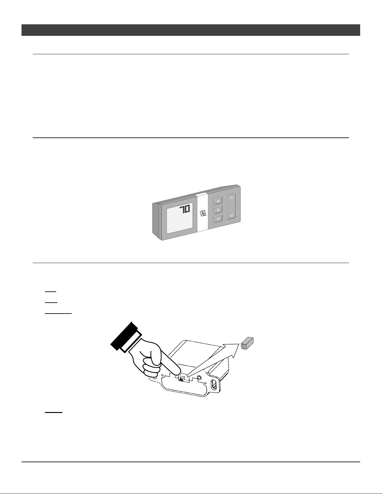
The fireplace may be directly operated from the battery holder (accessed by removing the face). The three
positions are below (see Figure 3):
ON – Burner turns on (regardless of transmitter settings).
OFF – Burner turns off (regardless of transmitter settings).
REMOTE – Burner is controlled by the transmitter.
ON REMOTE OFF
NOTE: When the battery holder switch is turned to ON or OFF, the mode settings (Flame Height, Comfort
Control) will remain in the same state as before the switch was moved (i.e.: the IFC “remembers” the last
setting). If you wish to adjust the mode settings use the transmitter mode button to adjust the settings.
The thermostat and burner on/off operating functions will not work on the transmitter.
Figure 3
© Travis Industries 1/11/2021 - 1521 430 EG GSR2
Page 31
Operation 31
Continuous/Intermittent Pilot Switch
This heater may run with the pilot continuously running or in intermittent mode. For most homeowners,
the intermittent mode is preferred (this saves fuel, doesn’t give off un-needed heat). However, in some
situations, the homeowner may prefer to switch the heater to continuous pilot. The most typical reasons
for switching to continuous pilot are:
Very Cold Conditions – in very cold conditions you may notice that the burner does not light quickly,
and the flames lift off the burner. If this is the situation, we recommend you switch to continuous pilot.
This will create a slight draft in the vent, allowing for the burner to light quickly and draft correctly.
Excessive Condensation on Glass After Startup – certain installations may encounter excessive
fogging on the window after startup (not just the first time the heater was started). This is an aesthetic
condition that may be remedied by switching the heater to continuous pilot.
Cold Glass or Heater Front – in very cold conditions you may notice that the heater front and glass
become very cold. To remedy this, switch the heater to continuous pilot.
Frequent On / Off Operation – if you are frequently turning the heater on and off, you may wish to
leave it in continuous pilot. This allows the burner to turn on more quickly, without pilot ignition delay.
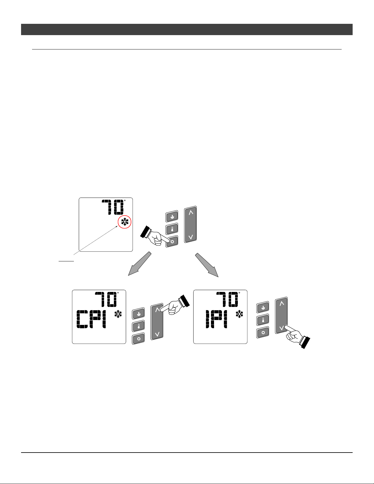
Switching from Intermittent (IPI) to Continuous Pilot (CPI)
The pilot mode on this appliance is adjusted using the remote. With the remote in the off position
(thermostat off, manual off), follow the directions below to adjust the pilot mode.
F
Press the "MODE" button
when the appliance is off to
adjust the IPI/CPI.
NOTE: This icon appears
when the appliance is in
CPI mode.
Press the "UP" button
to activate CPI mode.
Figure 4
Press the "DOWN" button
to activate IPI mode.
FF
© Travis Industries 1/11/2021 - 1521 430 EG GSR2
Page 32
32 Operation
Remote Operation
When the switch on the battery holder is set to “REMOTE” the transmitter operates the fireplace. Once
you understand how the transmitter works, you will be able to operate your fireplace quickly and easily.
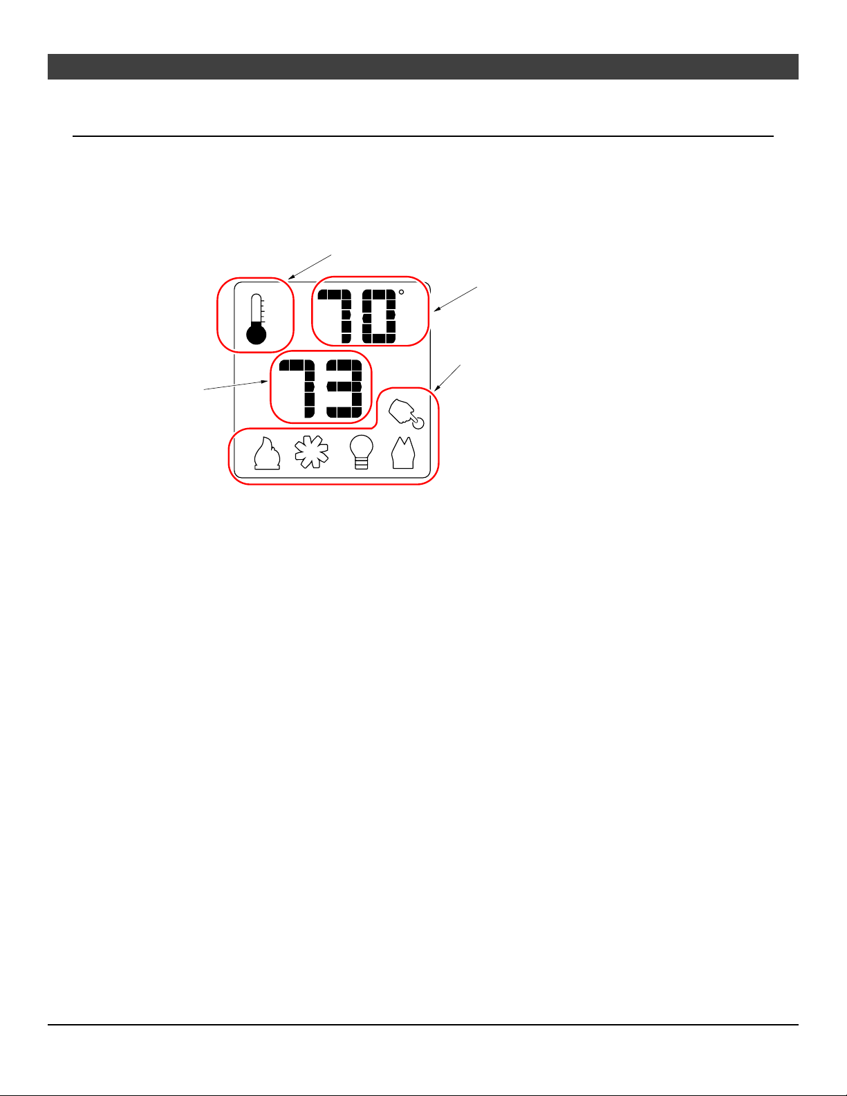
Display Overview
The transmitter display has four main sections (see Figure 5).
Thermostat Display
Room Temperature Display
F
ON
Mode Display (Flame, Blower, Light, Comfort Control)
Read-Out
(Thermostat Setting,
Function, etc.)
Figure 5
Listen for the “Beep”
Each time you press a button on the transmitter that controls the fireplace, a “beep” will come from the
IFC. When you change thermostat target settings the IFC will not beep.
NOTE: When the batteries start to get low, the IFC will beep twice whenever a button is pressed. When
the batteries are nearly depleted, the IFC will no longer beep. See “
IFC Batteries” on page 36).
© Travis Industries 1/11/2021 - 1521 430 EG GSR2
Page 33
Operation 33
Manual On-Off / Smart Thermostat / Standard Thermostat
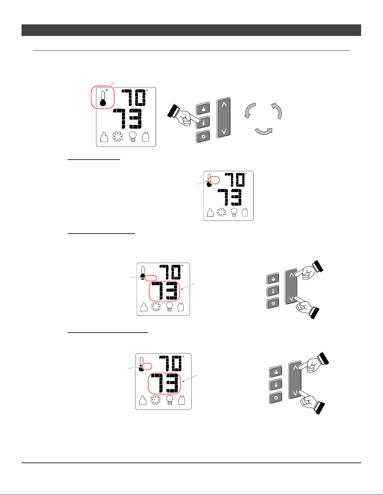
Use the thermostat button to cycle through the three thermostat settings (see Figure 6).
Look here for the
thermostat setting.
F
ON
Press the thermostat button to cycle
through the thermostat settings.
OFF
ON
Figure 6
SMART
MANUAL ON/OFF – The burner will turn on and off using the remote (see Figure 7). Press the
On/Off button to control the burner. When off, the display will only show the current temperature.
When in manual setting, the
OFF
word "OFF" will appear here.
Figure 7
F
SMART THERMOSTAT – While in smart thermostat, the transmitter will control the burner to
achieve the target temperature (see Figure 8 below). Flame height will be adjusted up or down to
allow operation without turning the burner on and off (also called “smart modulation”). To adjust
the target temperature, press the UP and DOWN buttons until a suitable temperature is achieved.
F
When in smart thermostat
setting, the word "SMART"
will appear here.
SMART
This is the target
temperature on the read-
out. Use the up or down
buttons to adjust the target
temperature.
Figure 8
STANDARD THERMOSTAT - While in standard thermostat setting, the transmitter will turn the
burner on and off to achieve the target temperature (see Figure 9 below). To adjust the target
temperature, press the up and down buttons until a suitable temperature is achieved.
F
When in standard thermostat
setting, the word "ON" will
appear here.
ON
This is the target
temperature on the
read-out. Use the up or
down buttons to adjust
the target temperature.
Figure 9
NOTE: If the transmitter batteries go dead while in thermostat setting (standard or smart), the appliance
will shut off after approximately 24 hours.
© Travis Industries 1/11/2021 - 1521 430 EG GSR2
Page 34
34 Operation
Mode Controls (Flame, Blower, Light, Comfort Control, EmberBed Light)
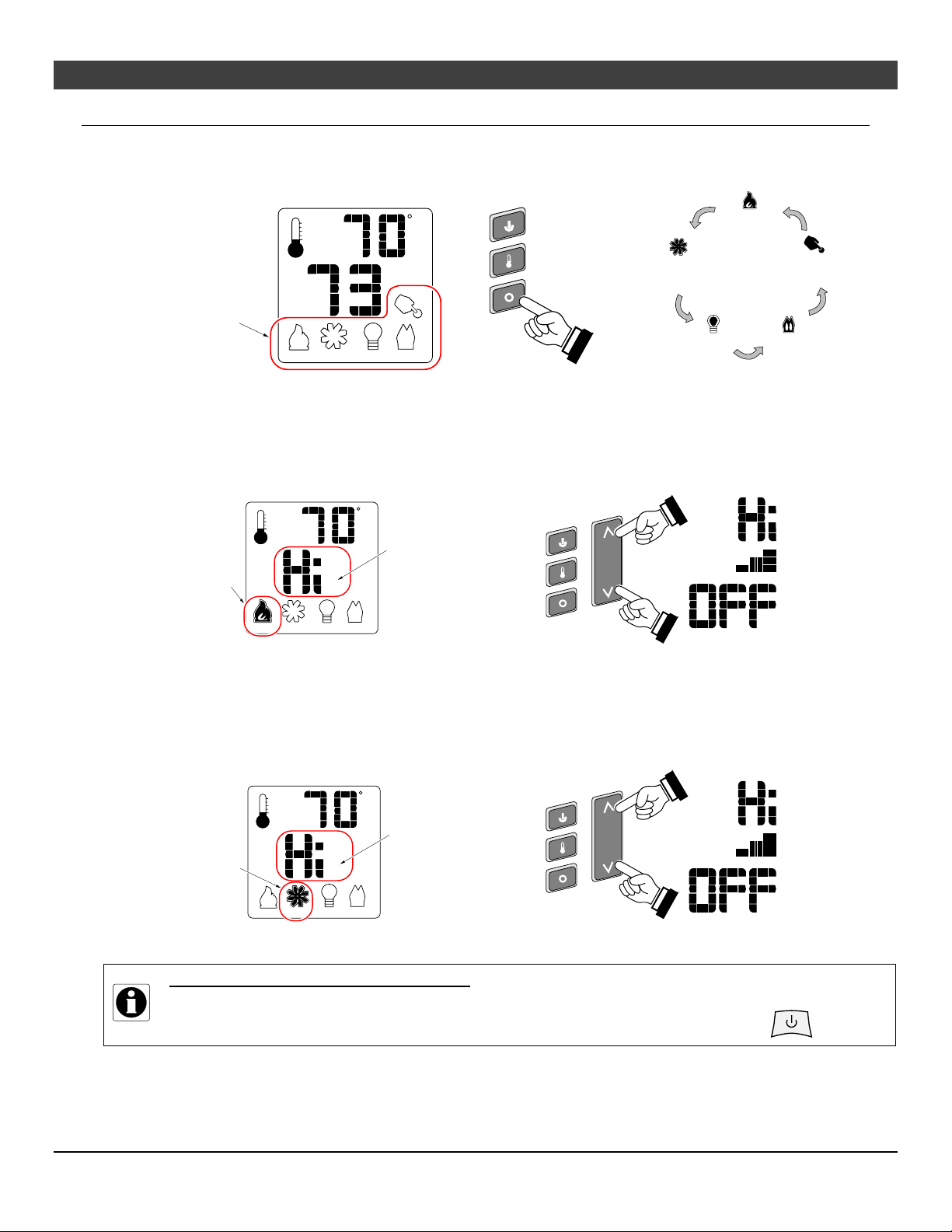
Use the mode button to cycle through the rive mode controls (see Figure 10 below).
Press the mode button to cycle through the mode settings.
F
OFF
Flame
Height
Optional
Blower
Look here for
mode controls.
Accent
Light
Figure 10
Flame Height
Flame height may be controlled using the UP and DOWN buttons when in Flame Height Mode (see
11
below). The center display will display the 7 settings, from “OFF” to “HI” for full on.
NOTE: Flame height may not be adjusted if operating in Smart Thermostat setting.
F
When in flame height
mode, this icon will
appear darkened.
OFF
MAX
This is the flame height
read-out. Use the up or
down buttons to adjust
the flame height (7
settings).
Figure 11
AUX
Comfort
Control
Figure
High
Medium
Off
Blower Speed
The blower may be controlled using the up and down buttons when in Blower Speed Mode (see
The center display will display the 7 settings, from “OFF” to “HI” for full on.
F
OFF
When in blower
mode, this icon will
appear darkened.
MAX
This is the blower
speed read-out. Use
the up or down buttons
to adjust the blower
speed (7 settings).
Figure 12
MANUAL MODE – BLOWER OPERATION
When in Manual Mode the blower will remain on, even if the burner is turned off and the heater cools.
Either manually turn the blower off, or turn off the heater by pressing the On/Off button.
Figure 12).
High
Medium
Off
© Travis Industries 1/11/2021 - 1521 430 EG GSR2
Page 35
Operation 35
Mode Controls - continued
Accent Light
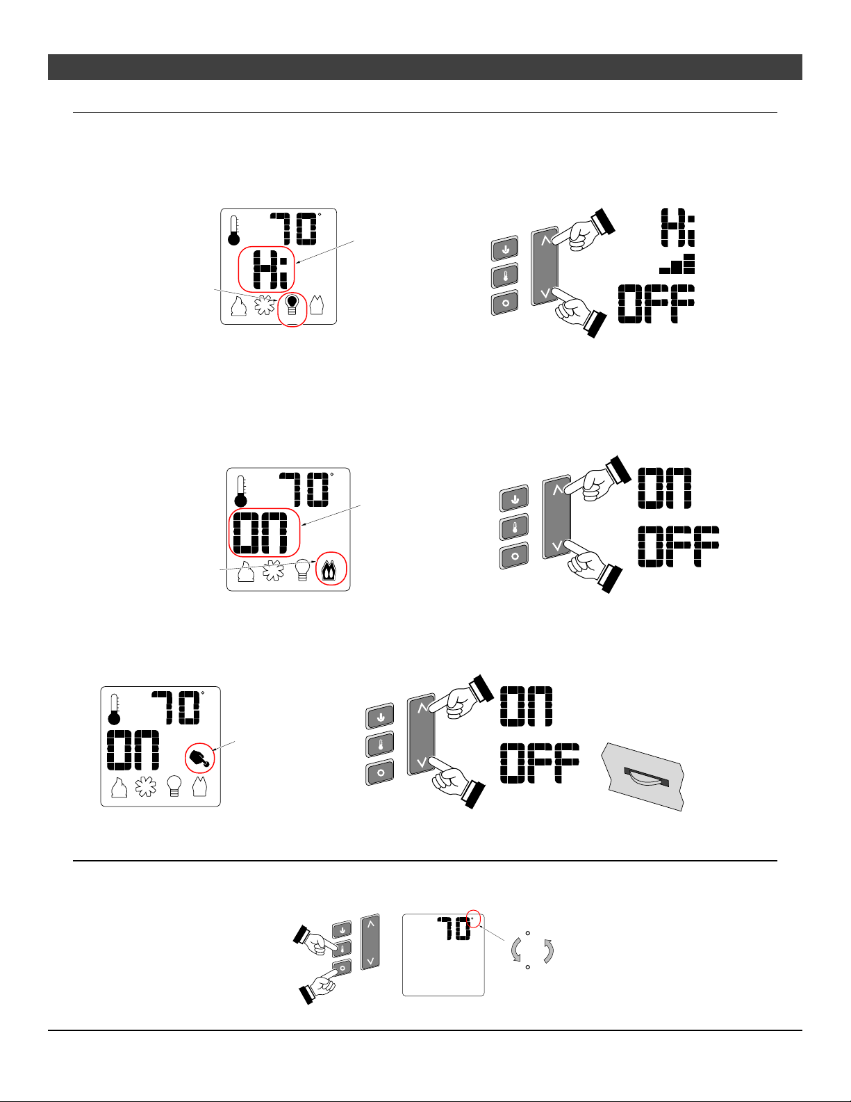
The Accent Light (night light) inside the heater may be turned on and off using the up and down buttons
when in Accent Light Mode (see illustration below). The center display will display the 7 settings, from
“OFF” to “HI” for full on.
F
This is the accent light
read-out. Use the up
or down buttons to
adjust the accent light
brightness (7 settings).
When in accent light
mode, this icon will
appear darkened.
OFF
MAX
HINT: If you wish to leave the accent light on while turning the burner off, adjust the Flame Height to
“OFF” (see above).
Comfort Control (rear burner)
The comfort control (rear burner) may be turned on and off using the up and down buttons when in
Comfort Control Mode (see illustration below). The center display will display either “ON” or “OFF”.
F
OFF
When in comfort
control mode, this
icon will appear
darkened.
This is the comfort
control read-out. Use
the up button to turn
on, down button to
turn off (2 settings).
High
Medium
Off
On
Off
EmberBed Light (AUX)
The emberbed light may be turned on and off using the up and down buttons (see illustration below). You
can adjust the brightness of the emberbed light using the built-in rheostat.
Use the rheostat on the
fireplace to control the
EmberBed brightness.
EM B ERBED LIGHT
OFF
F
When in EmberBed
mode (AUX), this
icon will appear
darkened and the
readout will display
status.
Display Fahrenheit or Celsius
With the system in the “OFF” position, press both the MODE and THERMOSTAT buttons
simultaneously to toggle between Fahrenheit (F) and Celsius (C).
F
F
C
© Travis Industries 1/11/2021 - 1521 430 EG GSR2
Page 36
36 Operation
Low Battery Indicator
Transmitter Batteries
The transmitter has a battery-level indicator. When it indicates low battery voltage (see Figure 13 below), install
three new AAA alkaline batteries into the transmitter (see “
36).
Low Battery Indicator
OFF
Transmitter Battery Installation” on page
F
MAX
Figure 13
IFC Batteries
The IFC (Integrated Fireplace Control) will “beep” twice when a transmitter button is pressed when the
batteries are low. Install four new AA alkaline batteries into the battery box when this occurs (see
“
Battery Installation” on page 36). In applications where the appliance is required to provide heat,
we recommend replacing the batteries before each heating season.
Battery Replacement
Battery Installation
Install four AA batteries into the battery holder (see Figure 14 below). These batteries act as a power
backup in case the household (AC) current goes out.
Transmitter Battery Installation
Install the three included AAA batteries into the remote.
AA Battery
AA Battery
AAA Battery
AAA Battery
AAA Battery
°F
AA Battery
AA Battery
Figure 14
Power Outages
The remote will work if household current (AC power) is disconnected. The batteries inside the battery
box will continue to power the heater but the accent light and blower will not operate.
© Travis Industries 1/11/2021 - 1521 430 EG GSR2
Page 37
Operation 37
P
T
s
w
E
I
(
w
Child-Proof Feature
The child-proof feature disables the control buttons, preventing un-wanted use of the remote.
Press both the MODE and UP buttons simultaneously to turn this feature on and off.
HINT: This feature is especially useful while using the thermostat setting.
Child Proof Indicator
F
OFF
Normal Operating Sounds
xtinction Pops
t is not unusual, especially on Propane
LP) appliances, to experience a "pop"
hen the burner is shut off.
ilot Assembly
he pilot flame will make a clicking
ound when starting up. If left on, it
ill make a slight whisper sound.
MAX
The appliance may creak with change of
temperature -- THIS IS NORMAL.
Blower(s)
The blower(s) push heated air into the
room. You will hear the sound of air
movement that increases as the speed is
increased.
Gas Control Valve
As the gas control valve is turned
on and off you will hear a dull
clicking sound. This is the valve
opening up and shutting down.
Figure 15
Normal Operating Odors
This appliance has several areas that reach high temperatures. Dust or other particles in these areas
may burn and create an odor. This is normal during start-up. You may notice the smell is more acute if
the appliance was left idle for a long period.
© Travis Industries 1/11/2021 - 1521 430 EG GSR2
Page 38
38
Maintenance
DANGER HIGH VOLTAGE: Disconnect power before attempting maintenance or repair.
Maintaining Your Heater's Appearance
Fingerprints or other marks left on the optional plated surface may become etched in place if they are not
wiped clean prior to turning the heater on. Clean the plated surfaces with denatured alcohol and a soft
cloth (with the heater cool). Other cleaners may leave a film that may become etched into the surface.
Accent Light Replacement
The accent lights in your heater provide additional lighting. The bulbs will burn out over time. To replace,
follow the directions below:
1. Shut off gas to the heater and let it cool for 15 minutes.
2. Remove the glass (see page 21) and media.
3. Replace the halogen bulbs with the following bulbs:
NOTE: Take care to not touch the bulbs with your fingers – use foam packing or a paper towel to
handle the bulbs:
35 Watt 120 Volt T4 Halogen Bulb (GY6.35 Base)
Upper Accent Lights
The upper accent light can be accessed by removing the 4 screws with a ¼” nut driver, as shown below.
The upper accent light assembly drops down to expose the accent light.
When replacing the assembly, carefully insert the wiring into this cavity to ensure the wiring is
not pinched.
The upper accent light may now be accessed.
© Travis Industries 1/11/2021 - 1521 430 EG GSR2
Page 39
Maintenance
Loosen the two screws nearest the bulb to disengage the bulb
from the holder. Remove the bulb from the holder. Replace
the bulb, making sure not to touch the bulb with your fingers
(grasp the bulb with the bulb packaging or a paper towel).
Tighten the screws until the bulb is secure (do not overtighten; this may damage the electrical contacts on the bulb).
Do not loosen these screws
Micro (1/16") Standard
or Philips Screwdriver
Ember-Glo Bulb Replacement
The Ember-Glo lights in your insert provide additional lighting and a more realistic fire appearance. The
bulbs will burn out over time. Replace the halogen bulbs with the following bulbs:
35 Watt 120 Volt T4 Halogen Bulb (GY6.35 Base)
To replace, follow the directions below:
1. Shut off gas to the Insert and let it cool for 15 minutes.
2. Remove the glass assembly (see page 22).
3. Remove Ember Glass, Ember Nuggets from the media tray.
(they hold the wires in place).
39
HINT: It is easier to remove the media tray if
you first remove the (4) logs indicated
below.
1. Lift the media tray skirt upward and remove it from the firebox.
2. Remove the (2) media tray attachment screws and lift the media tray up and out of the firebox.
Remove (2)
Media Tray
Screws
© Travis Industries 1/11/2021 - 1521 430 EG GSR2
Page 40
40 Maintenance
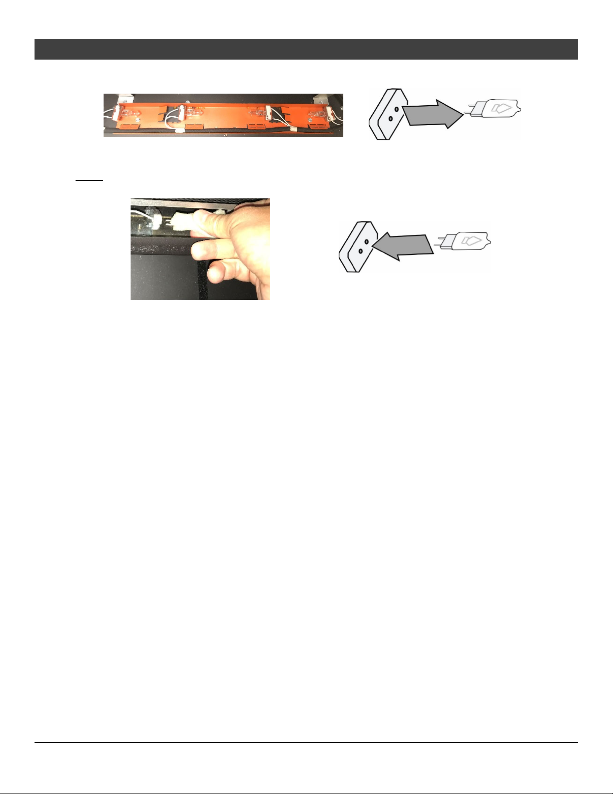
5. Locate the burned-out bulb and remove it from the socket by pulling the bulb directly away from
socket (do not twist).
6. Gently insert the pins on the replacement bulb into the holes on the socket.
(NOTE: Take care to not touch the replacement bulbs with your fingers – use foam packing or paper
towel to hold the bulb)
7. Return the fireplace to its correct configuration.
© Travis Industries 1/11/2021 - 1521 430 EG GSR2
Page 41
Maintenance 41
Yearly Service Procedure
WARNING: Failure to inspect and maintain the stove may lead to improper combustion and a potentially
dangerous situation. We recommend the following procedures be done by a qualified
technician.
Shut off gas to the fireplace and let it cool for 15 minutes. Remove the glass. Inspect and operate the
pressure relief mechanism to verify relief mechanisms are free from obstruction to operate.
Clean glass window with a suitable fireplace glass cleaner. Abrasive cleaners must not be used. Be
careful not to scratch the glass when cleaning.
Vacuum and clean any debris in the firebox.
Check all accessible gas-carrying tubes, connections, pipes, and other components for leaks.
Inspect the burner and firebox. Make sure the burner is not warped, cracked, or damaged. Check the
firebox and area around the pilot to make sure there is no damage. Inspect primary air openings for
blockage. If any problem is found, discontinue use and contact your dealer for service.
Inspect the area behind the access door; clean if necessary. Check the gas control valve and the gas
lines. If damage is found, discontinue use and contact your dealer for service. Clean the air channels,
ducts, and blower (if applicable)
Inspect vent and vent termination for sooting, obstructions, or damage. Make repairs as needed.
Remove any debris or vegetation near the vent termination. Contact your dealer if any sooting or
deterioration is found near the vent termination.
Reinstall the glass assembly. If the glass is damaged, replace it. Make sure the gasket along the
perimeter of the glass contacts the face of the firebox and forms an air-tight seal. If it does not, re-align or
replace the gasket to ensure an air-tight seal.
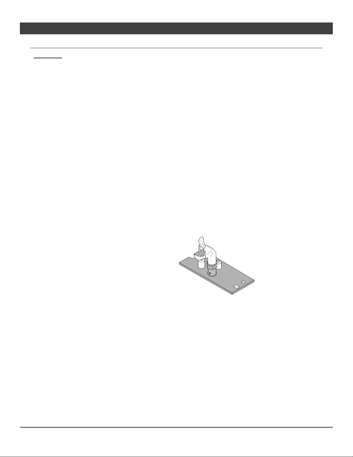
Turn the pilot flame on (continuous pilot). It should touch approximately 3/8" of the top of the flame
sensor (see below). If it does not, contact your dealer.
MV Pilot
GS Pilot
Start the main burner. Inspect and ensure the lighting of the main burner occurs within 4 seconds of the
main gas valve opening.
Test the flame failure response time of the flame safety system. It must de-energize the safety shutoff in
no more than 30 seconds.
After 15 minutes the flames should be orange/yellow and not touch the top of the firebox. If the pilot or
main burners do not burn correctly, contact your dealer for service. Monitor blower operation
© Travis Industries 1/11/2021 - 1521 430 EG GSR2
Page 42
42 Maintenance
Troubleshooting Table
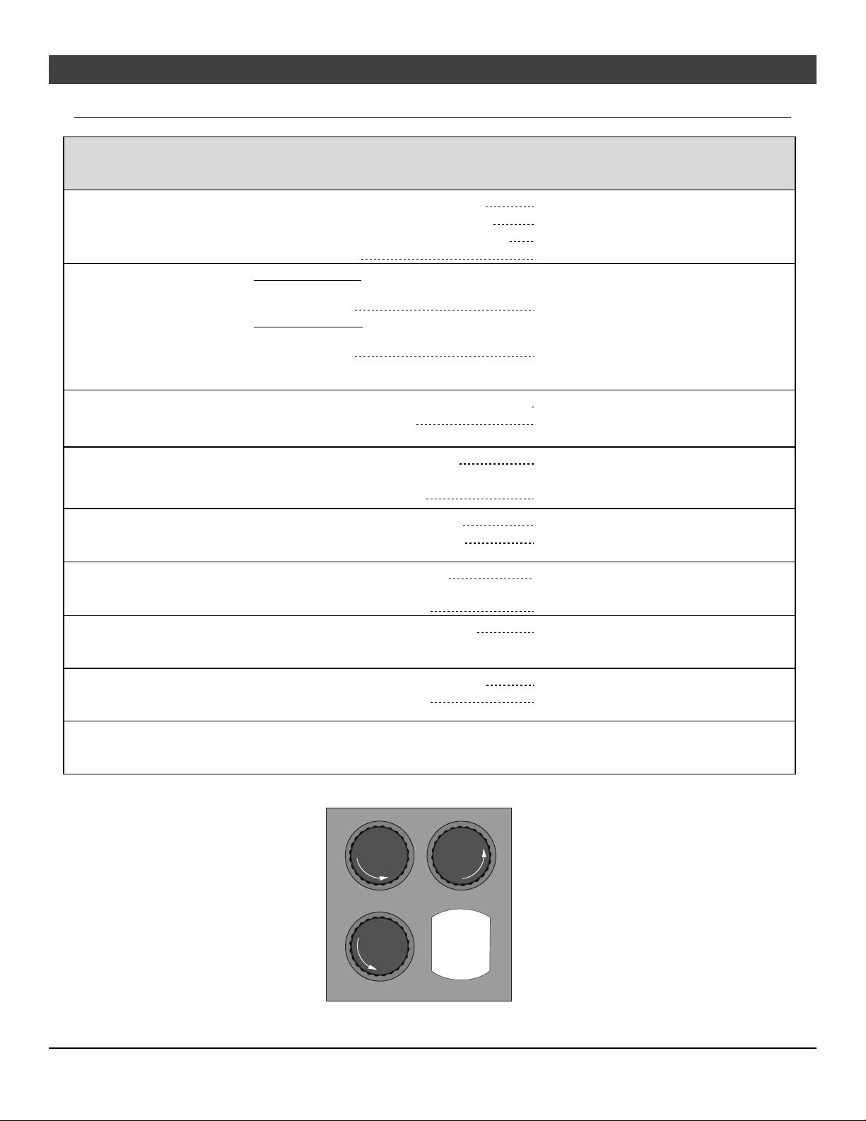
Problem: Possible Cause: Don't Call for Service Until
You:
Main Burners Will
Not Start
Appliance Beeps
Thermostat Does Not
Work
The battery box switch is turned to "OFF"
The remote control is not working correctly
The thermostat is disconnected or set too low
No propane in tank
Heater beeps once:
The heater beeps once whenever a button on the
remote is pressed
Heater beeps twice:
The heater beeps twice whenever a button on the
remote is pressed
The battery box switch is turned to "OFF" or “ON”
The thermostat is set too low
Turn the battery box switch to "ON".
See the remote control instructions.
See "Thermostat Operation".
Check Tank Level.
THIS IS NORMAL
The power backup batteries are low.
Replace the 4 AA batteries in the battery
box (see page 36).
Turn the battery box switch to “REMOTE”.
Check thermostat.
Blower Does Not
Work
Fireplace Will Not
The fireplace is not getting electricity
The fireplace is not up to temperature ..................
The blower fuse may be blown
The fireplace is not getting electricity
The fireplace is not up to temperature
Distribute Heat
Flames Are Too Blue
Rear Flames Are Too
The fireplace has just been started
Improper air shutter adjustment
The flame height may be turned too low
Short (Under 6")
Thin Layer of Soot
The media or coals are placed incorrectly
Improper air shutter adjustment
Covers the Glass
Accent Light Does
The bulb may be burned out. ................................
The accent light fuse may be blown. ....................
Not Work
Location of fuses (3 amp) in lower right corner under the firebox:
F
Lights
U
S
E
Check the breaker switch.
Let the fireplace burn for 10 minutes.
Replace the fuse. See fuse location below.
Check the breaker switch.
Let the fireplace burn for at least 15
minutes.
This is normal - see "Starting the Fireplace
for the First Time".
Adjust Air Shutter - contact your dealer.
Turn the flame height to "HI" -
See "Adjusting the Flame Height".
See "Media Installation".
Adjust air shutter - contact your dealer.
See “Accent Light Replacement” on page 38.
Replace the fuse. See fuse location below.
E
S
U
F
Fan
F
U
Ember-Glo
SE
Lights
© Travis Industries 1/11/2021 - 1521 430 EG GSR2
Optional power
cord location
Page 43
Maintenance 43
Wiring Diagram
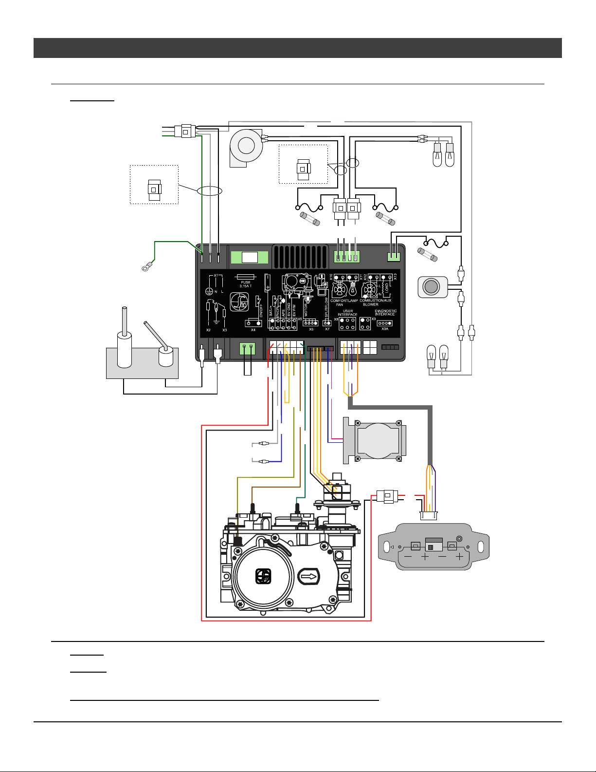
CAUTION: Label all wires prior to disconnection when servicing controls. Wiring errors can cause
improper and dangerous operation.
White
Power
In
May Include
Mole x
Blower(s)*
Black
May Include
Molex
Accent
Light (s)
Appliance
Ground
Flame
Detect
Spark
Rod
3 Amp
Fuse
Integrated Fireplace Control (IFC)
3.15A
FUSE
IPI/CP I
JUMPER WIRE
Red
Yellow
Blac k
Yellow / Green
Whit e
Orange
Blue
Green
System
Jumper
White
White
Black
Black
Grey
Ye l l o w
Purpl e
Blue
Orange
Pink
Comfort Control
Val ve
3 Amp
Fuse
Red
Black
3 Amp
Fuse
Rheostat
EmberBed
Lights*
Gre y
Orange
Purp le
Ye ll o w
TOP
(4) AA Batteries
Battery Box
(Manual On/Off)
Replacement Parts
Caution: Use only Travis Industries replacement parts. Do not use substitute materials.
Warning: Do not operate appliance with the glass front removed, cracked, or broken. Replacement of
the glass should be done by a licensed or qualified service person.
Contact your local Travis Industries Dealer for a Replacement Parts List
© Travis Industries 1/11/2021 - 1521 430 EG GSR2
Page 44
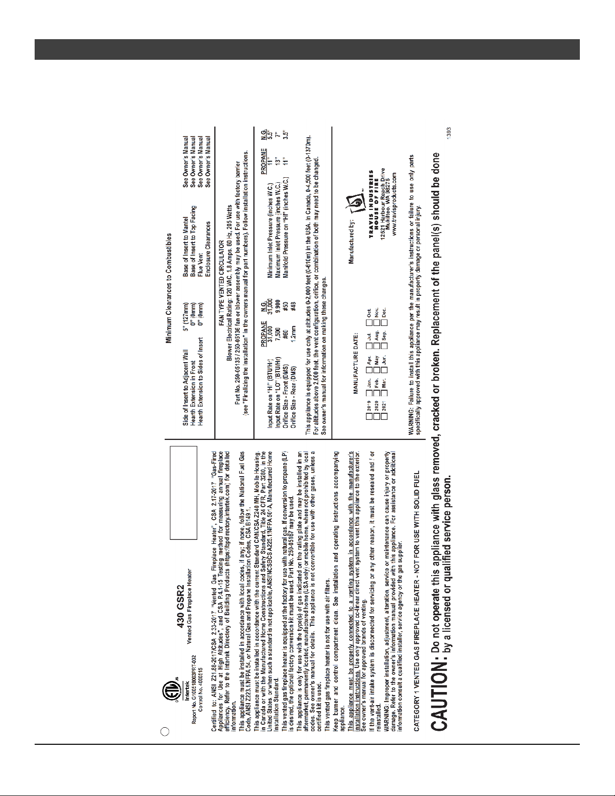
44 Safety Label
Safety Label
The safety (listing) label is attached to the operating tag (chained to the heater near the gas control
valve). A copy is shown below.
© Travis Industries 1/11/2021 - 1521 430 EG GSR2
Page 45
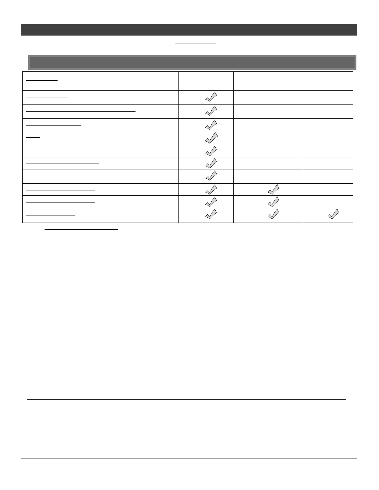
Limited 7 Year Warranty 45
Register your TRAVIS INDUSTRIES, INC. Limited 7 Year Warranty online at traviswarranty.com. TRAVIS INDUSTRIES, INC. warrants this gas appliance
(appliance is defined as the equipment manufactured by Travis Industries, Inc.) to be defect-free in material and workmanship to the original purchaser from the date
of purchase as follows:
Check with your dealer in advance for any costs to you when arranging a warranty call.
Mileage or service charges are not covered by this warranty. This charge can vary from store to store.
Component
Burner Assembly
Burner Pan Assembly, Air Shutter Assembly, Main Burner Orifice
Electrical Assembly (within heater structure):
Wiring harness, snap discs, rheostat speed control, blowers, etc.
Gas Control Assembly
Adjustable control valve, fireplace controller, pilot assembly, and pilot wiring
Glass
Glass (breakage from thermal shock)
Media
Log Set, Stones, etc.
Gold, Nickel & Copper Plating
Face & Door (see “Conditions and Exclusions” # 9)
Accessories
Firebacks, Power Heat Ducts, Andirons, etc…
One-Way Freight Allowance
One-way freight allowance on pre-authorized repair done at factory is covered.
Convection Heat Exchanger
Convection heat exchanger assembly
Firebox Assembly
Adjustable Air Restrictor, Pressure Relief Mechanisms, Glass Attachment Mechanism
Years 1 & 2
Parts & Labor
Years 3 Through 5
Parts & Labor
Years 6 & 7
Parts Only
EXCLUDED COMPONENTS:
Paint, Gasketing, and Accent Light Bulbs
CONDITIONS & EXCLUSIONS
1. This new gas appliance must be installed by a qualified gas appliance technician. It must be installed, operated, and maintained at all times in accordance with the instructions in the Owner’s
Manual. Any alteration, willful abuse, accident, neglect, or misuse of the product shall nullify this warranty.
2. This warranty is non-transferable and is made to the ORIGINAL purchaser, provided that the purchase was made through an authorized TRAVIS dealer.
3. Discoloration and some minor expansion, contraction, or movement of certain parts and resulting noise, is normal and not a defect and, therefore, not covered under warranty. The installer must
ensure the appliance is burning as per the rating tag at the time of installation. Over-firing (operation above the listed BTU rate) of this appliance can cause serious damage and will nullify this
warranty.
4. The warranty, as outlined within this document, does not apply to the chimney components or other Non-Travis accessories used in conjunction with the installation of this product. If in doubt as to
the extent of this warranty, contact your authorized TRAVIS retailer before installation.
5. Travis Industries will not be responsible for inadequate performance caused by environmental conditions such as nearby trees, buildings, rooftops, wind, hills, or mountains or negative pressure or
other influences from mechanical systems such as furnaces, fans, clothes dryers, etc.
6. This Warranty is void if:
a. The unit has been operated in atmospheres contaminated by chlorine, fluorine, or other damaging chemicals.
b. The unit is subject to submersion in water or prolonged periods of dampness or condensation.
c. Any damage to the unit, combustion chamber, heat exchanger, or other components due to water, or weather damage which is the result of, but not limited to, improper chimney/venting installation.
7. Exclusions to this 7 Year Warranty include: injury, loss of use, damage, failure to function due to accident, negligence, misuse, improper installation, alteration or adjustment of the manufacturer's
settings of components, lack of proper and regular maintenance, damage incurred while the appliance is in transit, alteration, or act of God.
8. This 7 Year warranty excludes damage caused by normal wear and tear, such as paint discoloration or chipping, worn or torn gasketing, corroded or cracked logs, embers, etc. Also excluded is
damage to the unit caused by abuse, improper installation, modification of the unit, drilling of the orifices, or the use of fuel other than that for which the unit is configured. Units are shipped for
natural gas and must be converted to propane using the included conversion kit. Confirm fuel configuration with your installer.
9. Damage to gold or nickel surfaces caused by fingerprints, scratches, melted items, or other external sources left on the gold or nickel from the use of cleaners other than denatured alcohol is not
covered in this warranty.
10. TRAVIS INDUSTRIES, INC. is free of liability for any damages caused by the appliance, as well as inconvenience expenses and materials. Incidental or consequential damages are not covered by
this warranty. In some states, the exclusion of incidental or consequential damage may not apply.
11. This warranty does not cover any loss or damage incurred by the use or removal of any component or apparatus to or from the gas appliance without the express written permission of TRAVIS
INDUSTRIES, INC., and bearing a TRAVIS INDUSTRIES, INC. label of approval.
12. Any statement or representation of TRAVIS products and their performance contained in TRAVIS advertising, packaging literature, or printed material is not part of this 7-year warranty.
13. This warranty is automatically voided if the appliance’s serial number has been removed or altered in any way. If the appliance is used for commercial purposes, it is excluded from this warranty.
14. No dealer, distributor, or similar person has the authority to represent or warrant TRAVIS products beyond the terms contained within this warranty. TRAVIS INDUSTRIES, INC. assumes no liability
for such warranties or representations.
15. Travis Industries will not cover the cost of the removal or re-installation of hearths, facing, mantels, venting, or other components.
16. If for any reason any section of this warranty is declared invalid, the balance of the warranty remains in effect and all other clauses shall remain in effect.
17. THIS 7 YEAR WARRANTY IS THE ONLY WARRANTY SUPPLIED BY TRAVIS INDUSTRIES, INC., THE MANUFACTURER OF THE APPLIANCE. ALL OTHER WARRANTIES, WHETHER
EXPRESS OR IMPLIED, ARE HEREBY EXPRESSLY DISCLAIMED AND PURCHASER’S RECOURSE IS EXPRESSLY LIMITED TO THE WARRANTIES SET FORTH HEREIN.
IF WARRANTY SERVICE IS NEEDED:
1. If you discover a problem that you believe is covered by this warranty, you MUST REPORT it to your TRAVIS dealer WITHIN 30 DAYS, giving them proof of purchase, the purchase date, and the
model name and serial number.
2. Travis Industries has the option of either repairing or replacing the defective component.
3. If your dealer is unable to repair your appliance’s defect, he may process a warranty claim through TRAVIS INDUSTRIES, INC., including the name of the dealership where you purchased the
appliance, a copy of your receipt showing the date of the appliance’s purchase, and the serial number on your appliance. At that time, you may be asked to ship your appliance, freight charges
prepaid, to TRAVIS INDUSTRIES, INC. TRAVIS INDUSTRIES, INC., at its option, will repair or replace, free of charge, your TRAVIS appliance if it is found to be defective in material or
workmanship within the time frame stated within this 7-year warranty. TRAVIS INDUSTRIES, INC. will return your appliance, freight charges (years 1 to 5) prepaid by TRAVIS INDUSTRIES, INC., to
your regional distributor, or dealership.
4. Check with your dealer in advance for any costs to you when arranging a warranty call. Mileage or service charges are not covered by this warranty. This charge can vary from store to store.
© Travis Industries 1/11/2021 - 1521 430 EG GSR2
Page 46
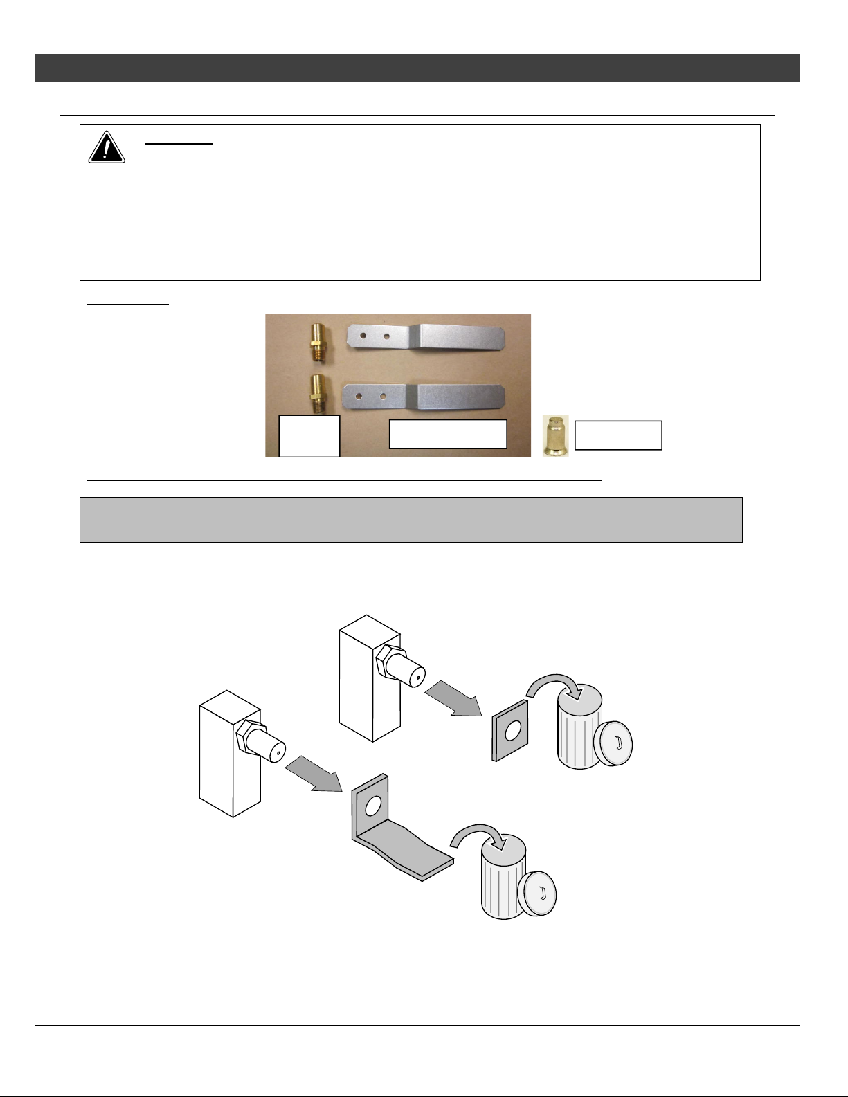
46 Optional Equipment (for qualified installers only)
LP Conversion Instructions
WARNING
This conversion kit shall be installed by a qualified service agency in accordance with the
manufacturer’s instructions and all applicable codes and requirements of the authority
having jurisdiction. If the information in these instructions is not followed exactly, a fire,
explosion, or production of carbon monoxide may result causing property damage,
personal injury, or loss of life. The qualified service agency is responsible for the proper
installation of this kit. The installation is not proper and complete until the operation of the
converted appliance is checked as specified in the manufacturer’s instructions supplied
with the kit.
Packing List
LP
Orifices
(2) LP Seal Plates
Pilot Orifice
Convert the appliance prior to installing the gas line to ensure proper gas use.
The GSR Stepper Motor Kit (4-pack = 94400999), (single = 250-01463) is required for converting
this appliance to LP. The kit contains the stepper motor (regulator) and Torx wrench.
1. Access the firebox.
2. Remove the burners (see “Remove the Burner,” in the owner's manual).
3. When using LP, remove and discard the two existing orifice gaskets (see below).
© Travis Industries 1/11/2021 - 1521 430 EG GSR2
Page 47
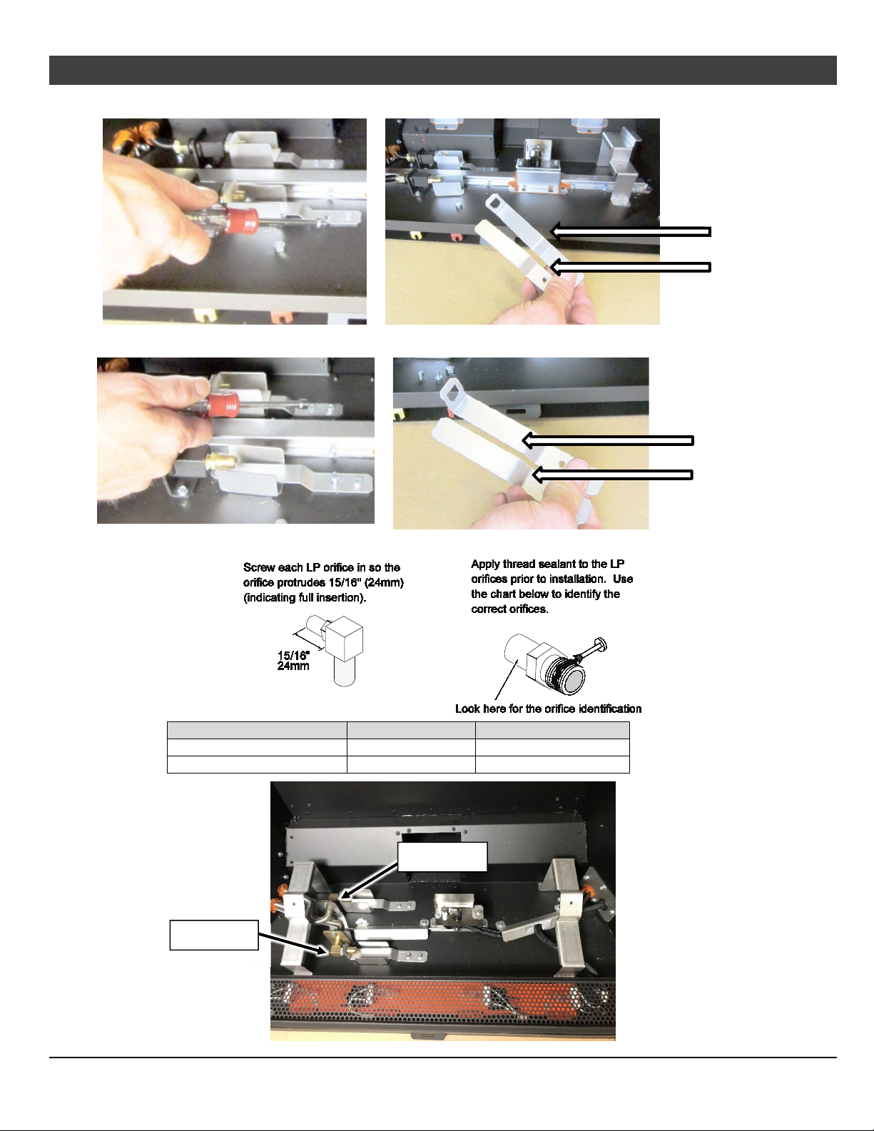
Optional Equipment (for qualified installers only)
4. Remove and discard the stock seal plates. Install the LP seal plates as shown below.
47
Stock Seal Plate
Stock Seal Plate
LP Seal Plate
LP Seal Plate
Stock Seal Plate
LP Seal Plate
5. Install the LP (propane) orifices.
ORIFICE SIZE (ID) Natural Gas LP (Propane)
Front Burner Orifice #48 DMS #60 DMS
Rear Burner Orifice #50 DMS 1.2mm DMS
Rear Orifice
Front Orifice
© Travis Industries 1/11/2021 - 1521 430 EG GSR2
Page 48
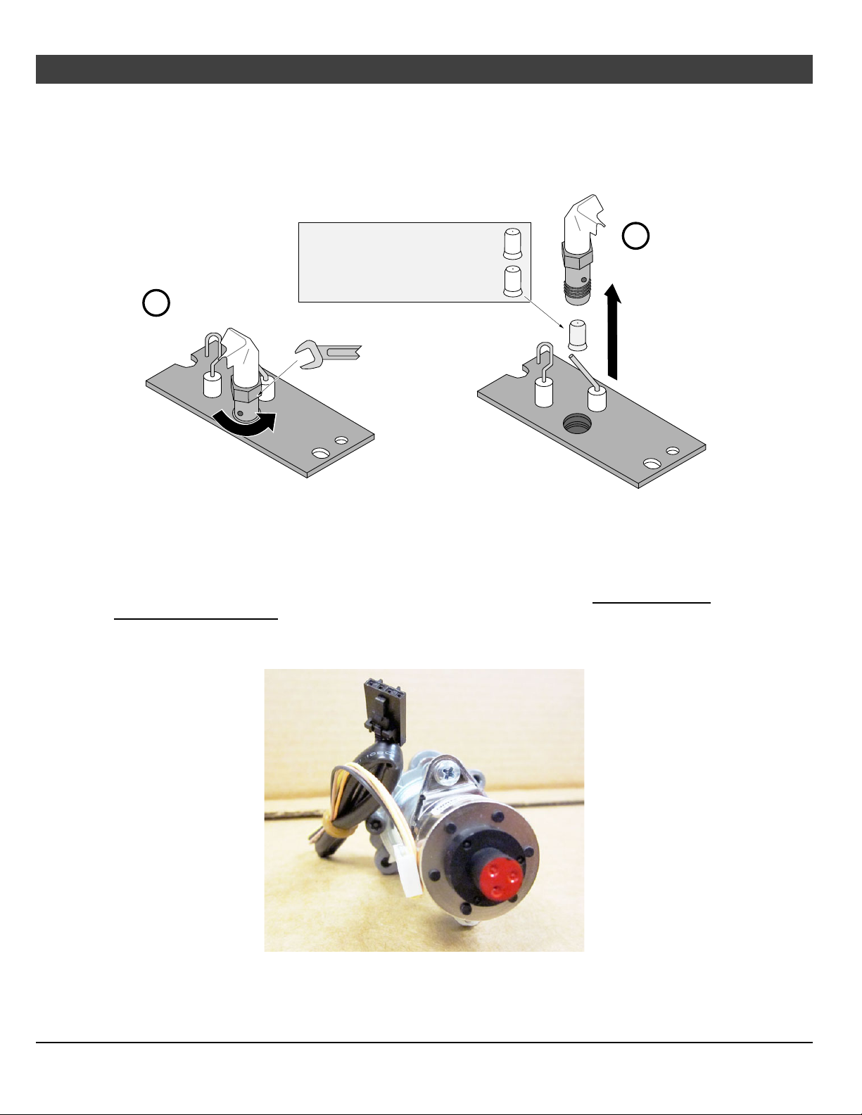
48 Optional Equipment (for qualified installers only)
6. Install the LP pilot orifice following the directions below.
(a) Use a 7/16” open-end wrench to remove the pilot hood.
(b) Remove and discard the Natural Gas (NG) orifice. Place the LP orifice in the pilot assembly then
replace the pilot hood, tightening the pilot hood until it is snug (do not over-tighten).
Natural Gas Orifice = .018N
LP (Propane) Orifce = .014LP
.018N
.014LP
b
a
7/16" Wrench
7. Replace the firebox components. Restore the fireplace to the correct configuration. Install the firebacks
before re-installing the burner.
8. Access the stepper motor (shown below). The stepper motor (adjustable regulator) has an installation
sheet included with it – make sure to follow all of the directions. Disconnect the wiring from the stepper
motor. Remove the stock stepper motor and replace with the LP version. – MAKE SURE IT IS
CORRECTLY ORIENTED. Secure using the screws included with the motor – tighten to 25 Lb-inches.
Leak test this area after installation to verify proper installation. Re-attach the wiring.
9. Restore the appliance to the correct configuration. Make the gas line connection, bleed the gas line (if
applicable), start the heater, and thoroughly leak-test all gas connections and the gas control valve.
© Travis Industries 1/11/2021 - 1521 430 EG GSR2
Page 49
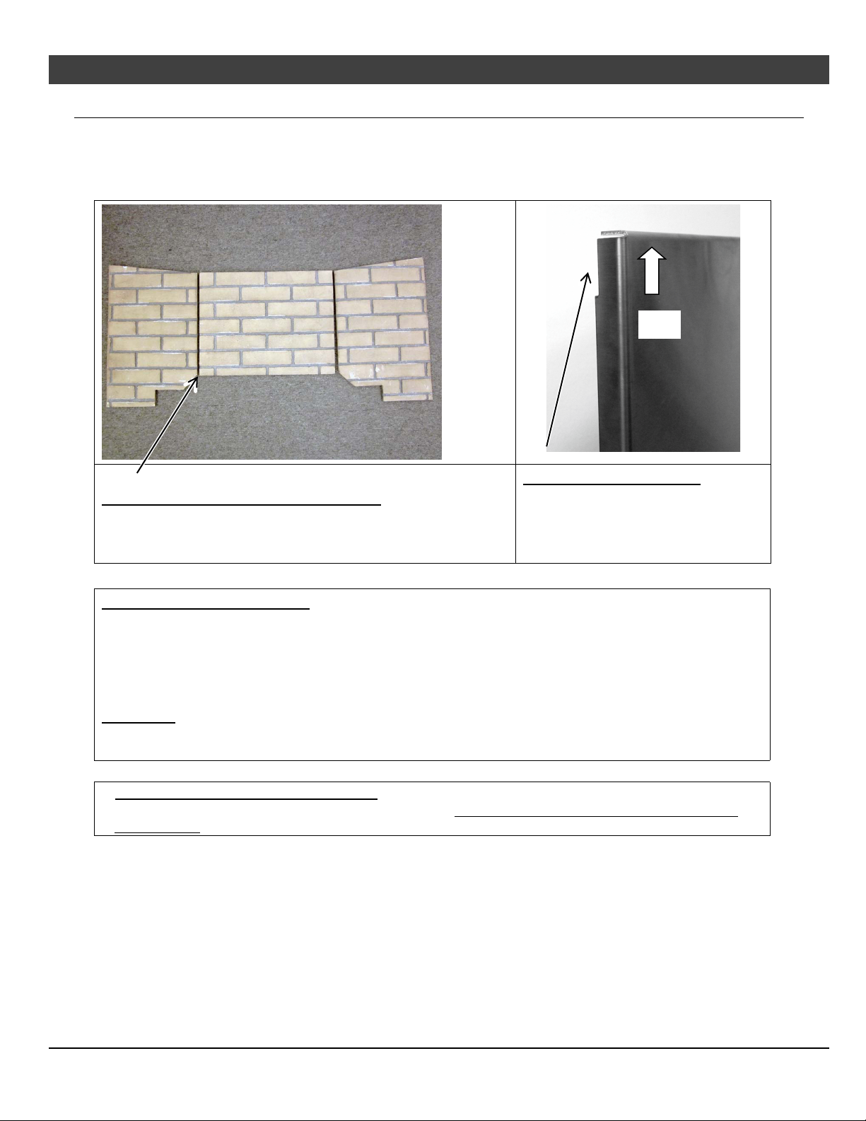
Optional Equipment (for qualified installers only) 49
Fireback Installation
Packing List
Rear, Left, and Right Firebacks
Up
Fireback Orientation – Ceramic Firebacks
The rear fireback is rectangular and must be placed right-sideup. Lay the firebacks on a flat surface prior to installing to verify
Metal Fireback Orientation
Make sure the notch is upwards
when installing.
the grout lines are aligned.
GLASS FIREBACK WARNINGS
HANDLING THE FIREBACKS: The glass firebacks are fragile – especially the edges. Take care to
prevent contacting/scraping the glass against metal or rough surfaces. You may wish to lay out a blanket
during installation in case you need to set the firebacks down.
We recommend the use of gloves and safety glasses during the installation of the glass firebacks.
CLEANING
These firebacks require periodic cleaning. Do not use ammonia-based cleaners (this may cloud the
glass). We recommend ammonia-free glass cleaner (i.e. vinegar and water) to clean the fireback.
CURING BLACK-PAINTED FIREBACKS
The black painted firebacks will fully cure under heat. Run the appliance on low for several hours to
cure the paint. The firebacks may be touched-up using Forrest “Metallic Black” paint.
© Travis Industries 1/11/2021 - 1521 430 EG GSR2
Page 50
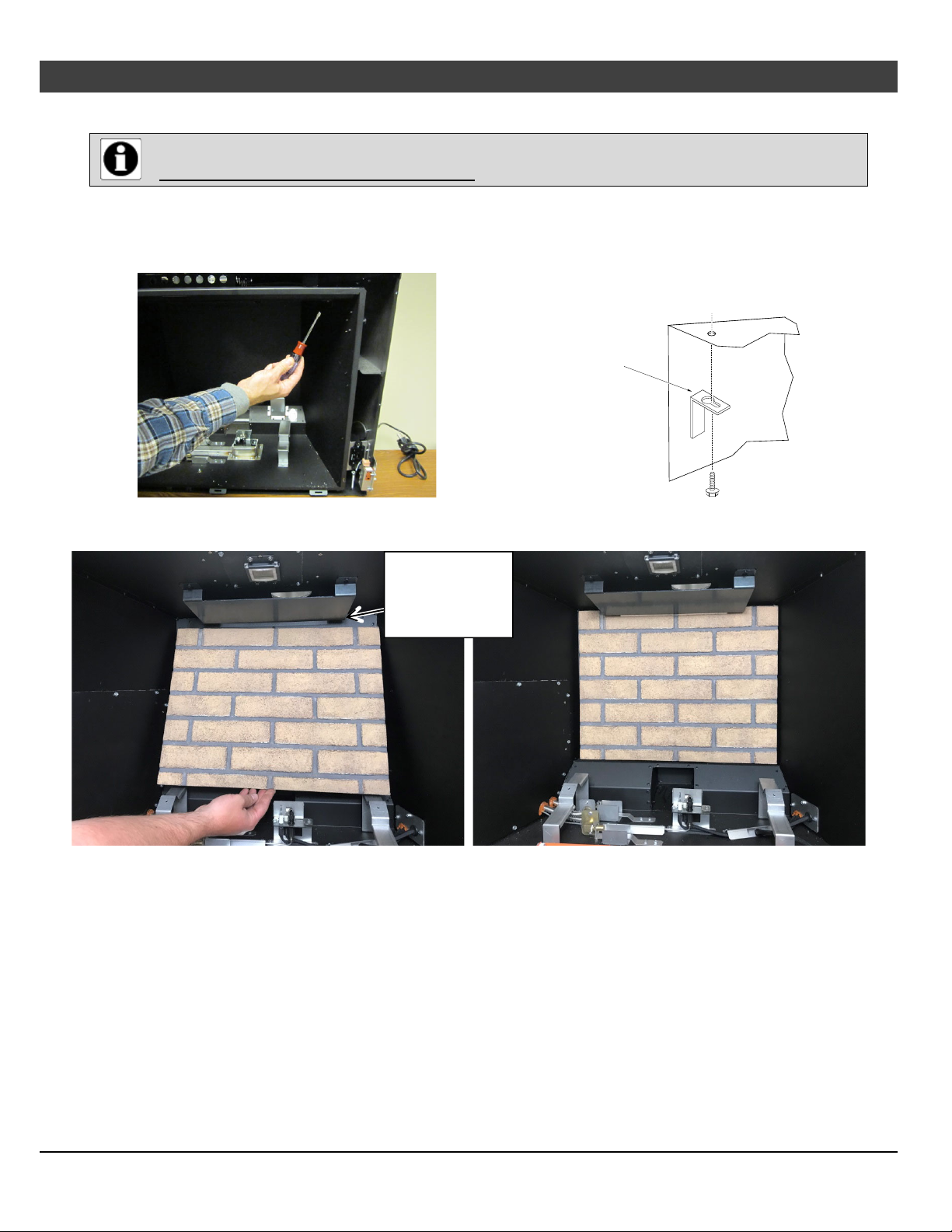
50 Optional Equipment (for qualified installers only)
Installation
The firebacks are installed with the burners removed.
See “Order of Installation” on pg. 7.
1. Remove the burner and media tray (see pg. 27).
2. Remove the two side fireback clips from the firebox ceiling. They are located at the outward edges of
the firebox near the glass opening.
The side fireback clip
has a keyhole slot. It
can be removed by
loosening the screw
and sliding the clip out.
3. Place the rear fireback inside the firebox as shown below. Make sure the
Tuck the fireback
behind the baffle
on the firebox
ceiling.
© Travis Industries 1/11/2021 - 1521 430 EG GSR2
Page 51
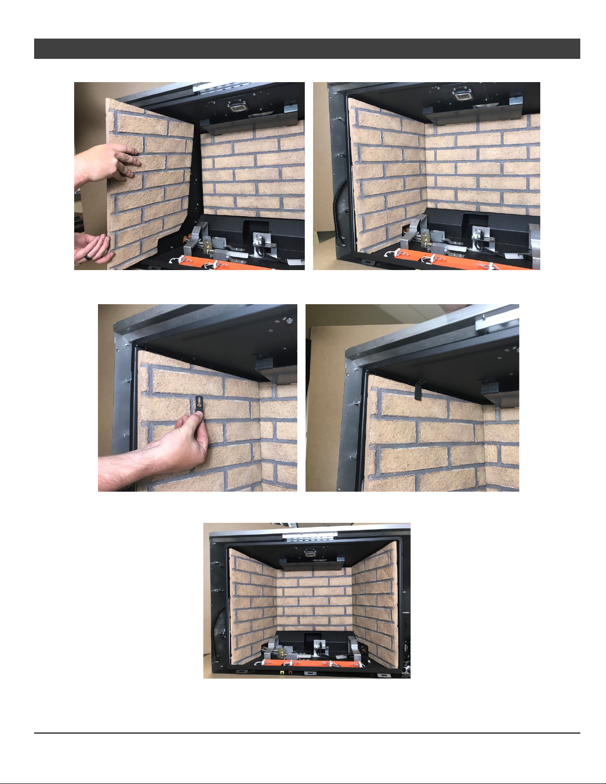
Optional Equipment (for qualified installers only) 51
4. While holding the rear fireback, install the left fireback into the firebox as shown below.
5. Replace the left fireback clip to secure the right fireback in place
6. Install the right fireback and secure using the fireback clip. The firebox should now look like the photo
below.
© Travis Industries 1/11/2021 - 1521 430 EG GSR2
Page 52
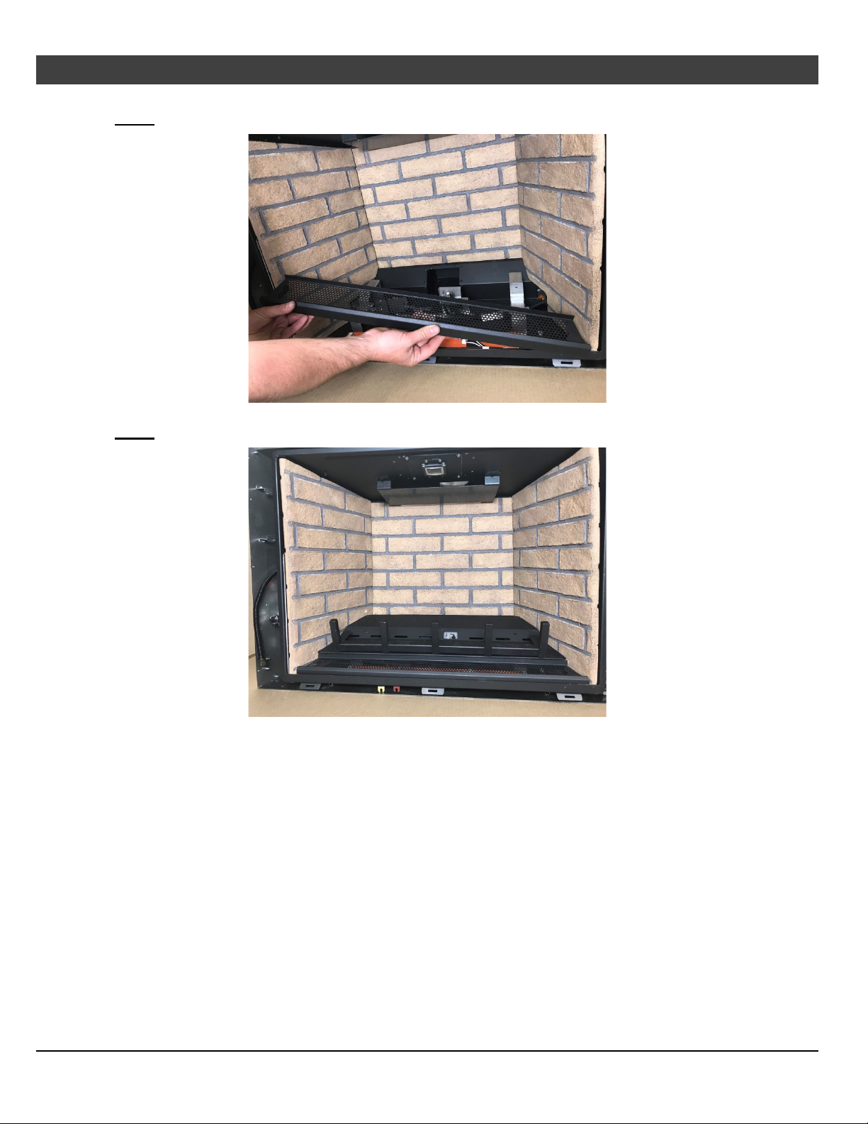
52 Optional Equipment (for qualified installers only)
7. Replace the media tray.
NOTE: The tray may not fit unless the firebacks are all the way against the fireback walls.
8. Replace the burner. Secure it with the 2 screws removed earlier.
NOTE: The burner may not fit unless the firebacks are all the way against the fireback walls.
© Travis Industries 1/11/2021 - 1521 430 EG GSR2
Page 53
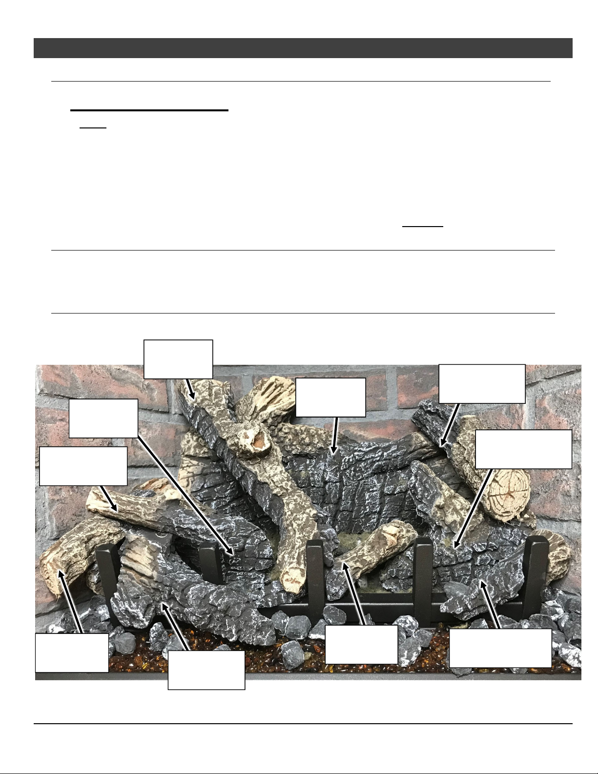
Optional Equipment (for qualified installers only)
Oak and Birch Log Set Installation (sku# 94500957, 94500956)
Installation Warnings
NOTE: Consult the installation manual for order of installation. If using propane (LP), convert the
appliance before installing the log set. Install the firebacks prior to installing the log set.
The logs are fragile, especially after being exposed to heat.
Make sure the gas control valve is OFF and the heater is cool prior to conducting service.
Failure to position the parts in accordance with these diagrams or failure to use only parts
specifically approved with this appliance may result in property damage or personal injury.
The burner must be correctly positioned before installing the log set. Make sure the burner is fully
seated and the pilot is properly aligned. See the owner’s manual for details on burner removal.
This appliance requires the use of a fireback kit. Install the Fireback BEFORE installing the logs.
Installation – Oak vs. Birch
Both log sets are nearly identical in shape. The only difference is the paint scheme and some textural
details. Page 2 contains a picture of the birch log set installed. The installation pictures show the classic
oak log set.
Log Set Overview – Oak (sku# 94500957)
When installed, the ten (10) logs should appear as shown below.
Left Log
250-05243
Center Log
250-05239
Back Log
250-05237
Right Top Log
250-05240
53
Center Left Twig
250-05238
Left Twig
250-05241
Front Left Log
250-05245
Center Twig
250-05242
Right Bottom Log
250-05244
Front Ember Chunk
250-05246
© Travis Industries 1/11/2021 - 1521 430 EG GSR2
Page 54
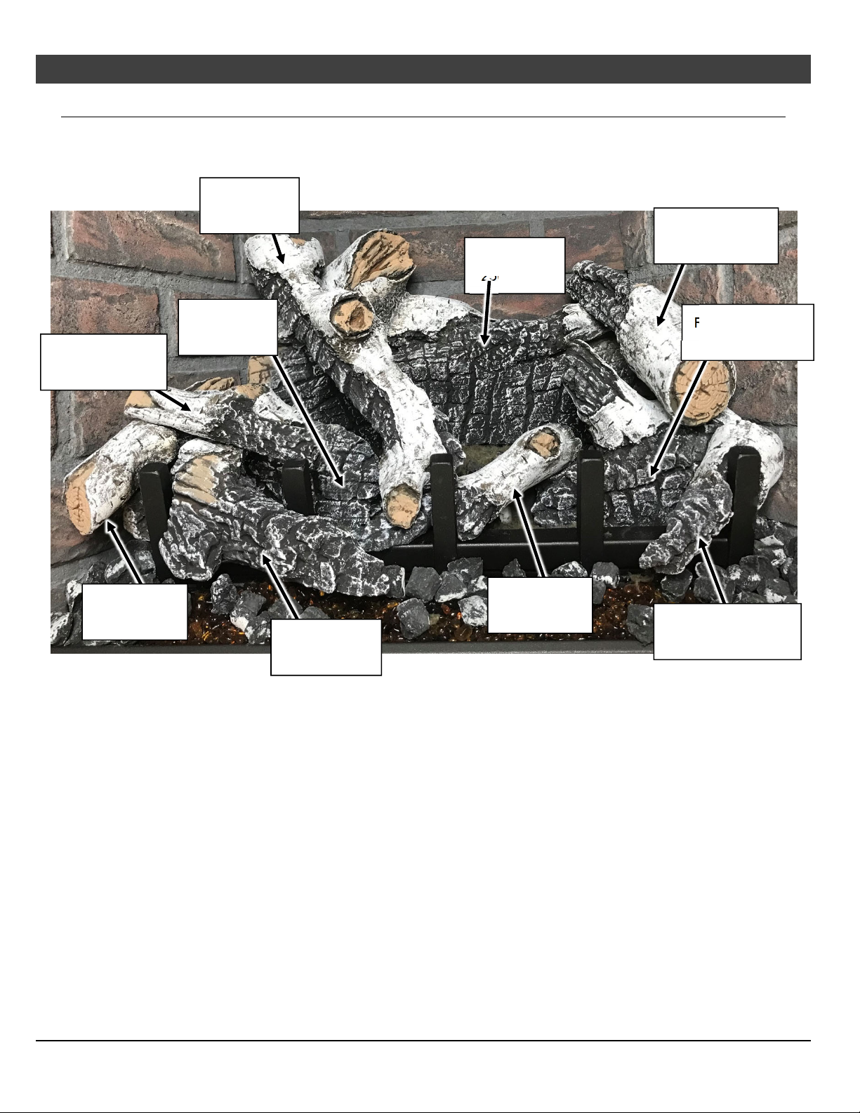
54
Optional Equipment
(for qualified installers only)
Log Set Overview – Birch (sku# 94500956)
When installed, the ten (10) logs should appear as shown below.
Center Log
250-05249
Back Log
250-05247
Right Top Log
250-05250
Center Left Twig
250-05248
Left Twig
250-05251
Left Log
250-05253
Front Left Log
250-05255
Center Twig
250-05252
Right Bottom Log
250-05254
Front Ember Chunk
250-05256
© Travis Industries 1/11/2021 - 1521 430 EG GSR2
Page 55
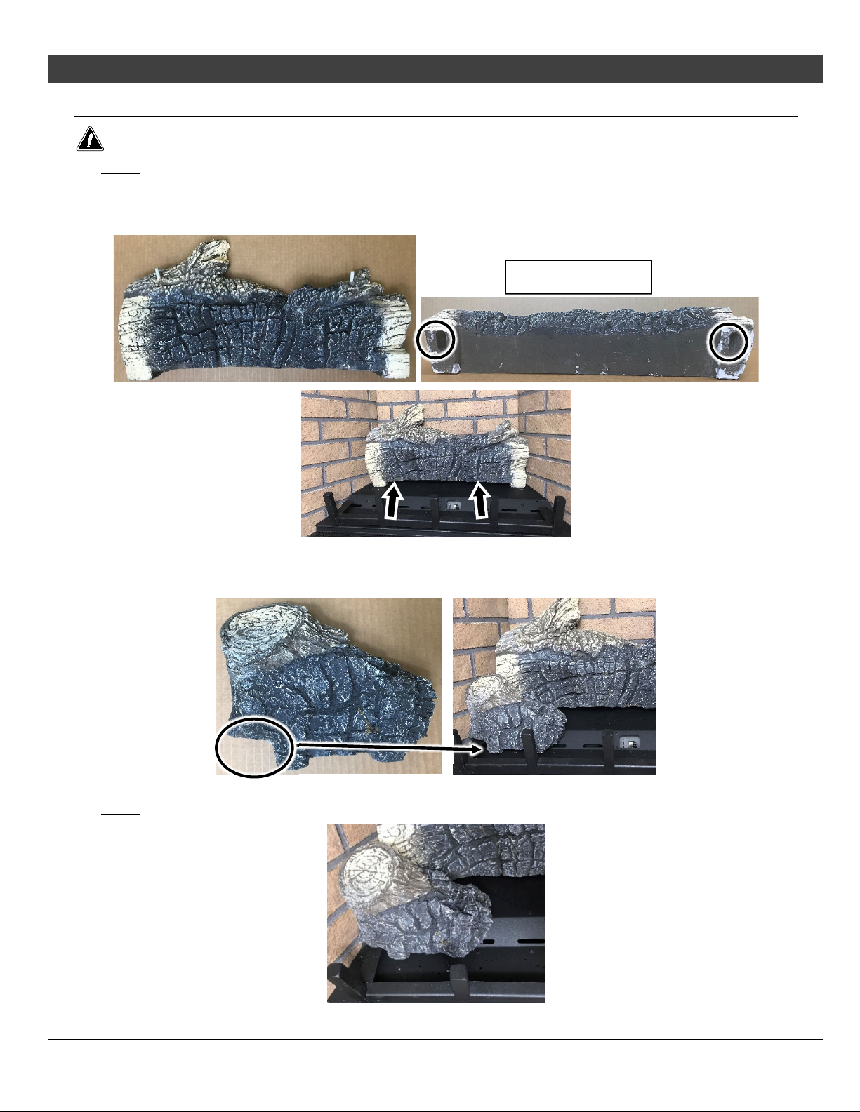
Optional Equipment (for qualified installers only)
Log Set Installation
The logs are fragile, especially after exposure to heat.
NOTE: The insert should be in place, with the gas line and vent attached and the firebacks installed (see
owner’s manual for further details).
1. Place the rear log as shown below. The two slots on the bottom of the log sit over the pin on the burner.
With the rear log in place, push it all the way back
Bottom View of Log
55
2. Place the left log on the lower front portion of the burner. The notch on the bottom left of the
log rests on the grate. Push the log backward until it is in contact with the sloped area between
the front and rear burner.
NOTE: Make sure the log does not obstruct any burner holes.
© Travis Industries 1/11/2021 - 1521 430 EG GSR2
Page 56
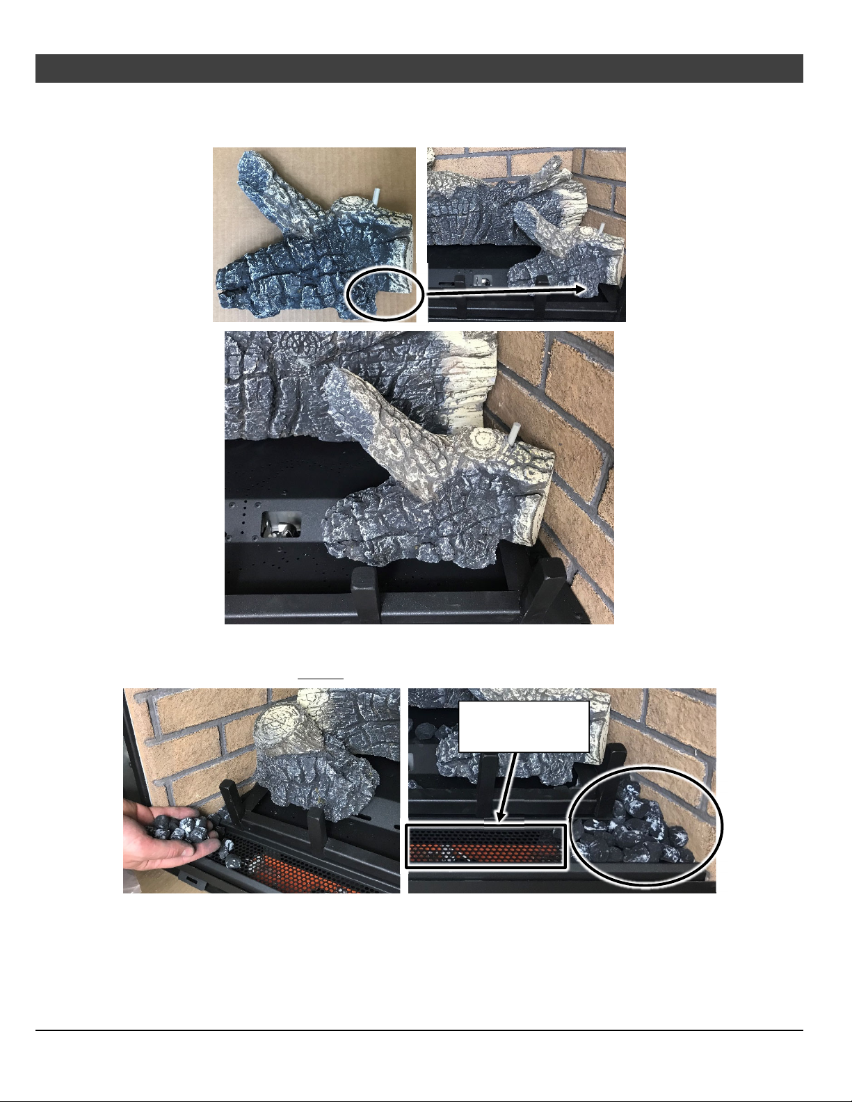
56
Optional Equipment
3. Place the right log as shown below. The notch on the bottom right of the log rests on the grate.
Push the log backward until it is in contact with the sloped area between the front and rear
burner. Make sure burner holes are not obstructed.
(for qualified installers only)
4. Detail around the burner with ember chunks. Cover any exposed metal between the side of the
grate and the side of the firebox. Stack ember chunks over any portion of the perforated metal
along the front of the unit that IS NOT over the Ember-Glo lights (see picture below to the right).
Do not cover
Ember-Glo lights
© Travis Industries 1/11/2021 - 1521 430 EG GSR2
Page 57
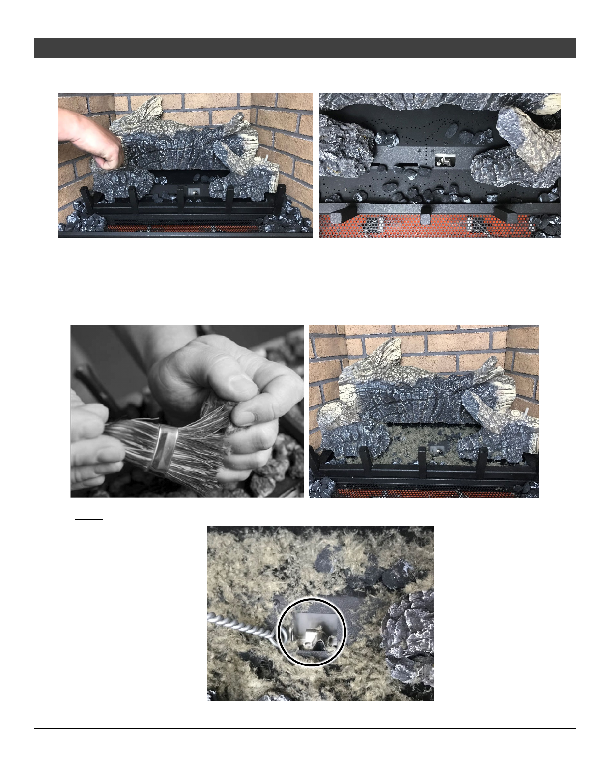
Optional Equipment (for qualified installers only)
5. Place ember chunks on any portion of the front or rear burner as long as it does not obstruct
any burner holes.
6. Detail the burner with Rock Wool. The included rock wool is placed on top of the burner to
enhance the glow from the burner. The rockwool can be applied in a relatively thick layer.
The best method for applying the rock wool is to brush it on to the burner. Compress a clump of
rockwool between your thumb and forefinger. Use a stiff brush to apply rockwool fibers onto the
burner. Do not use the entire bag of rockwool. Use only a small amount and save the
remainder. Over-use of rockwool will diminish the glow and may cause sooting or other adverse
conditions.
57
NOTE: Remove all rockwool from the pilot area (see below).
© Travis Industries 1/11/2021 - 1521 430 EG GSR2
Page 58
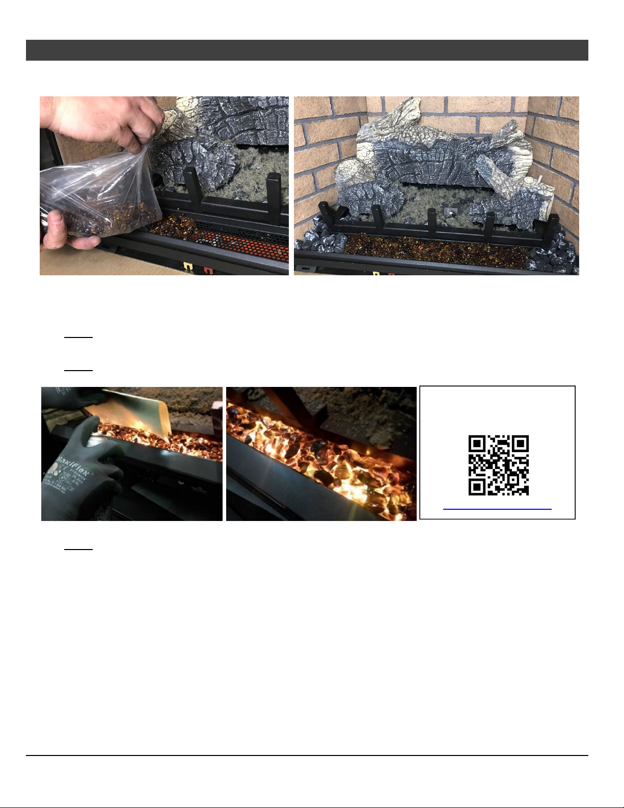
58
Optional Equipment
7. Install the Ember glass on the perforated area directly in front of the grate. Place a thick layer
of the ember glass over the perforations making sure to cover all of the holes.
8. Lightly dress the ember glass with the black touch-up paint provided. Check the appearance
with the lights on and add additional paint, as needed, for a realistic glowing ember
appearance.
NOTE: If power is supplied to the insert it can help to turn the lights on while painting so you can
determine an appropriate amount of paint for a realistic ember appearance.
NOTE: We recommend that you use a piece of paper, cardboard as a shield to mask the log grate and
burner from overspray (see below).
(for qualified installers only)
Scan this code with a QR
reader on your cell phone to
watch a video of the setup.
http://vimeo.com/289322734
NOTE: If power is supplied, turn the rheostat until the embers have a realistic and aesthetically pleasing
appearance. Use the remote to turn the Ember-Glo lights on and off.
© Travis Industries 1/11/2021 - 1521 430 EG GSR2
Page 59
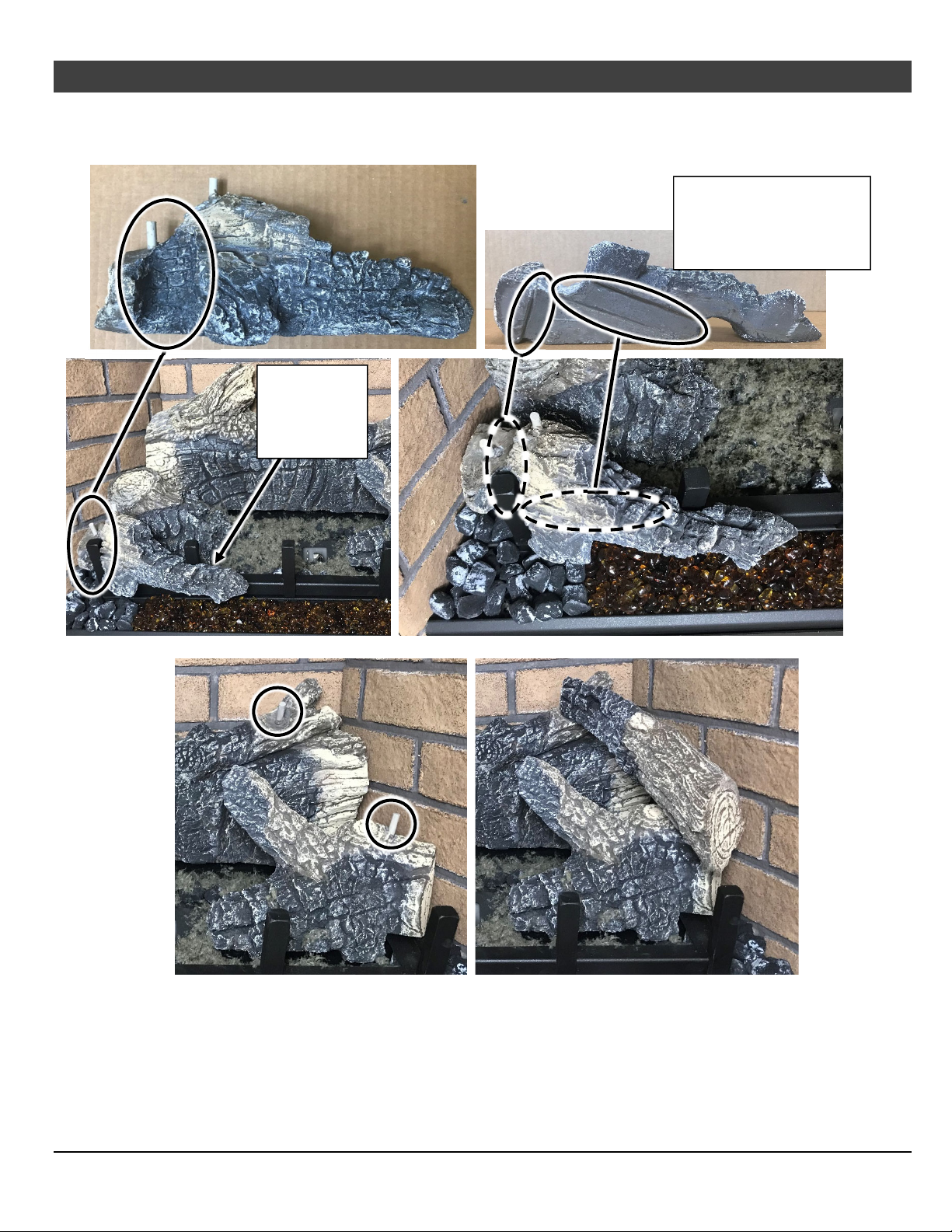
Optional Equipment (for qualified installers only)
9. Place the front left log as shown below. The log has a channel that orients it properly to the grate (see
below). The right end of the log sits forward of the second vertical finger of the grate. There are also two
channels on the bottom of the log that rest on the side and front edges of the burner.
The channels on the
bottom of the log rest on
the side and front of the
grate as shown below
Right end of
log sits in
front of
grate
59
10. The right top log has two slots on the back that fit over the pins on the rear and right log (see pictures below).
© Travis Industries 1/11/2021 - 1521 430 EG GSR2
Page 60
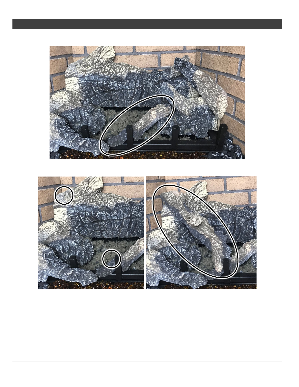
60
Optional Equipment
11. The center twig rests on rests on the tip of the right bottom log and has a notch that rests on the
middle vertical finger of the grate.
12. The center log rests on a pin on the left end of the rear log and the on the left end of the center
twig. There is a notch in the end of the log that rests against the grate.
(for qualified installers only)
© Travis Industries 1/11/2021 - 1521 430 EG GSR2
Page 61
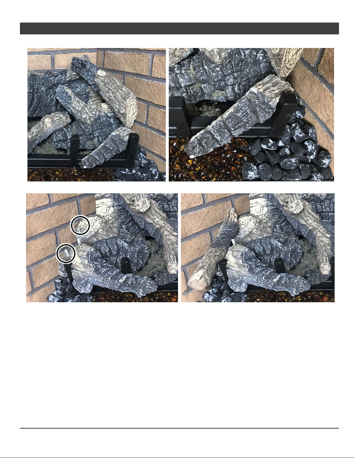
Optional Equipment (for qualified installers only)
13. Place the right ember chunk as shown below.
14. The left twig sets on the left most pin on the front left log and the top rests on the left log.
61
© Travis Industries 1/11/2021 - 1521 430 EG GSR2
Page 62
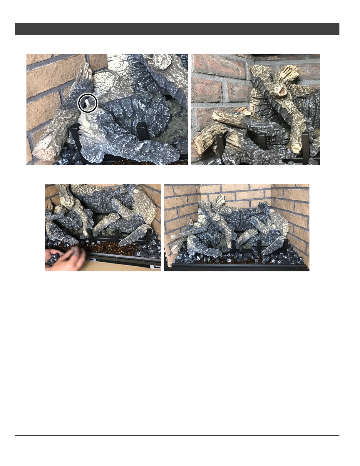
62
Optional Equipment
15. Place the center-left twig over the remaining pin on the front left log. The burnt end of the log
should rest on (or near) the grate.
16. Place any remaining ember chunks on the ember glass and grate to create a realistic
appearance.
(for qualified installers only)
© Travis Industries 1/11/2021 - 1521 430 EG GSR2
Page 63

Optional Equipment (for qualified installers only) 63
Driftwood Log Set Installation (sku# 94500953)
Installation Warnings
NOTE: Consult the installation manual for order of installation. If using propane (LP), convert the
appliance before installing the log set. Install the firebacks prior to installing the log set.
The logs are fragile, especially after being exposed to heat.
Make sure the gas control valve is OFF and the heater is cool prior to conducting service.
Failure to position the parts in accordance with these diagrams or failure to use only parts
specifically approved with this appliance may result in property damage or personal injury.
The burner must be correctly positioned before installing the log set. Make sure the burner is
fully seated and the pilot is properly aligned. See the owner’s manual for details on burner
removal.
This appliance requires the use of a fireback kit. Install the Fireback BEFORE installing the logs.
Order of Installation
When setting up the insert, you will need to follow a specific order of installation to optimize installation
time. Failure to have all of the accessories available at the time of installation will delay installation and
may lead to unnecessary disassembly of components.
1. Run gas line to the fireplace
2. Remove the glass frame.
3. Run vent through fireplace chimney. On larger fireplaces, the vent connector may be left in place. For
smaller fireplaces, remove the vent connector. See “Vent Connector Removal and Installation” for
details.
4. Place insert into position and attach the gas line and vent.
5. Remove the burner.
NOTE: If using propane (LP), convert the appliance at this time.
6. Install the firebacks.
7. Replace the burner.
8. Install the media (logs, stones - see instructions included with the media).
9. Install the surround panel (see instructions included with surround panel).
10. Replace the glass.
11. Install the face (see instructions included with the face).
12. Follow the instructions under “Finalizing the Installation”.
© Travis Industries 1/11/2021 - 1521 430 EG GSR2
Page 64
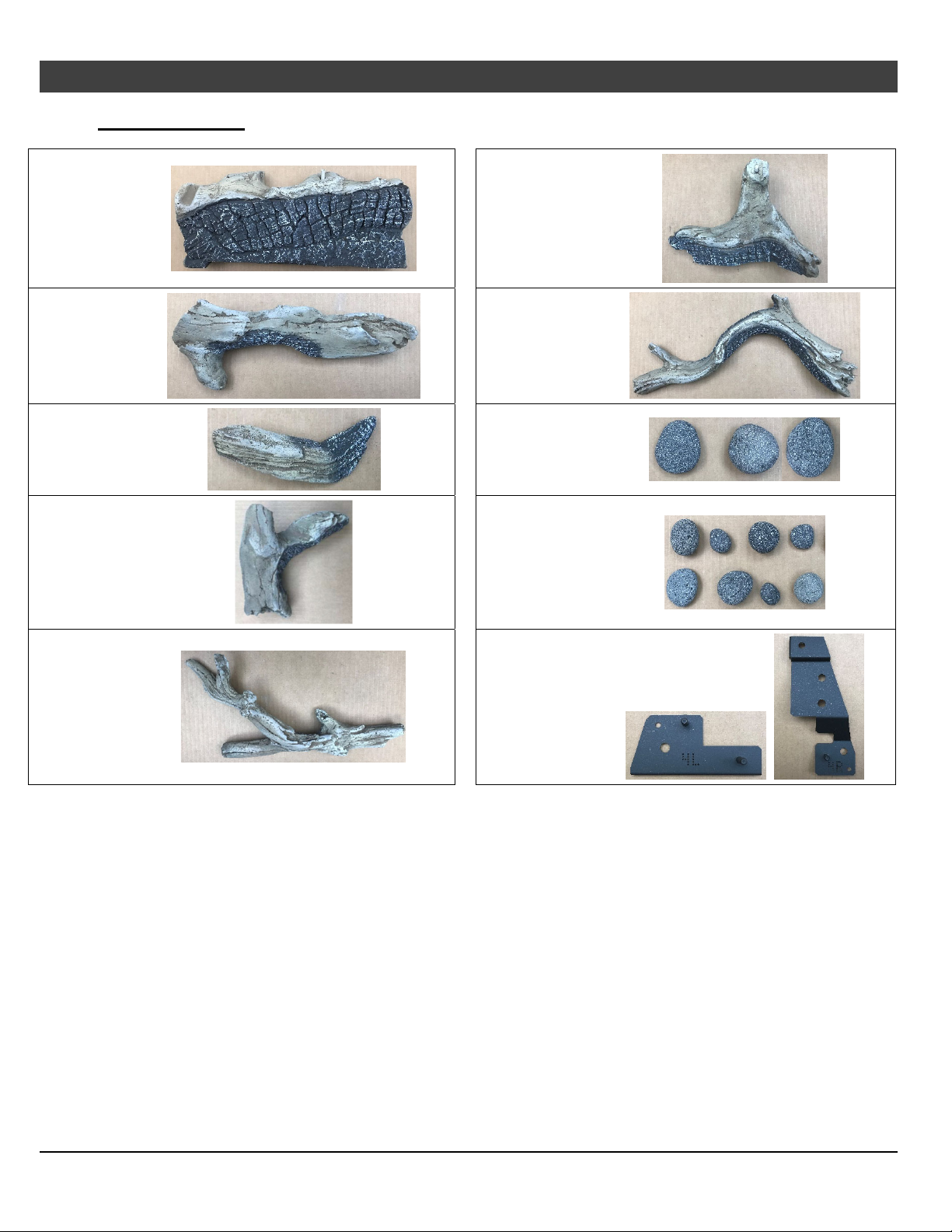
64
Optional Equipment
Packing List
(for qualified installers only)
Log #1
(250-05391)
Log #2
(250-05392)
Log #3
(250-05393)
Log #4
(250-05394)
Log #6
(250-05396)
Log #7
(250-05397)
(3) Large
Stones
(250-05404)
(8) Small
Stones
(250-05404)
Log #5
(250-05395)
Left (4L) and
Right (4R) Log
Brackets
© Travis Industries 1/11/2021 - 1521 430 EG GSR2
Page 65
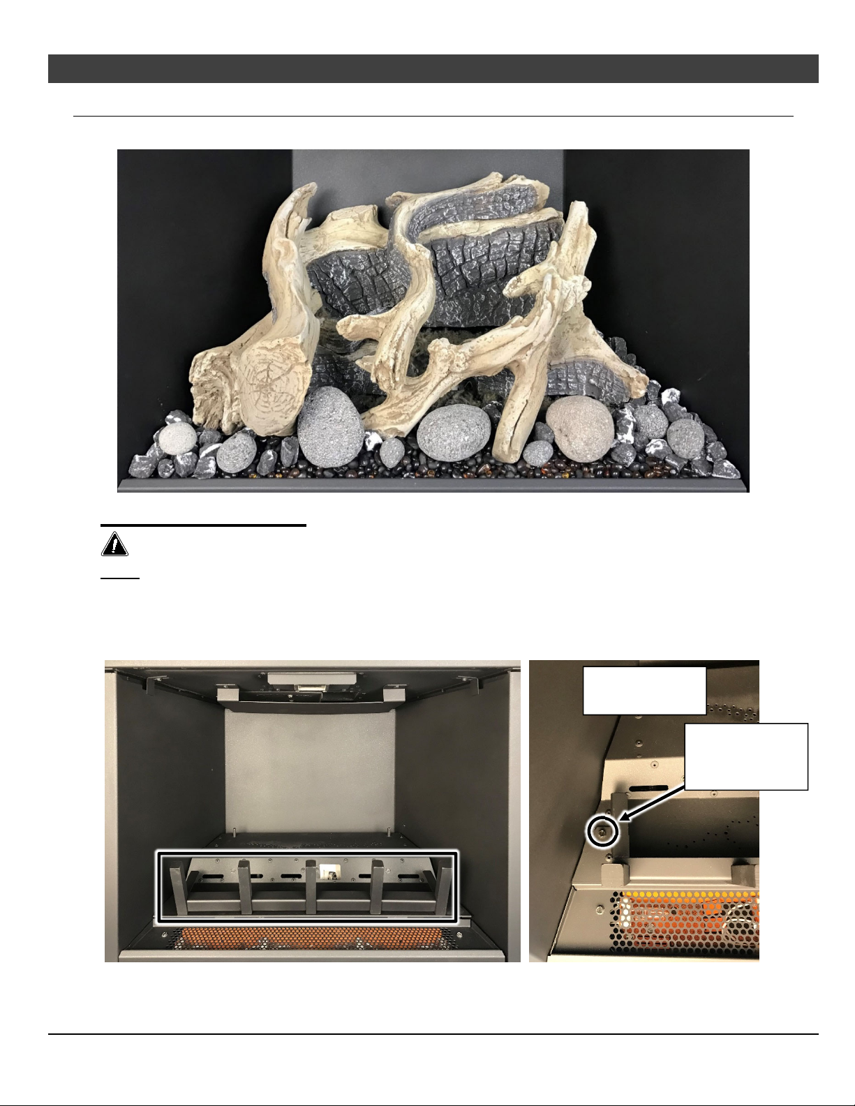
Optional Equipment (for qualified installers only)
Log Set Overview – Driftwood (sku# 94500953)
When installed, the seven (7) logs should appear as shown below.
65
Log Set Installation
The logs are fragile, especially after exposure to heat.
NOTE: The insert should be in place, with the gas line and vent attached and the firebacks installed (see
owner’s manual for further details).
1. Remove the glass frame assembly from the front of the insert (see installation manual for details).
2. Remove the log grate from the burner tray. The grate is secured by (2) 1/4” screws (one on each side of
the grate). Keep the (2) screws and discard the log grate.
Top View of Left
Side of Burner
Remove the
screws securing
grate to burner
© Travis Industries 1/11/2021 - 1521 430 EG GSR2
Page 66
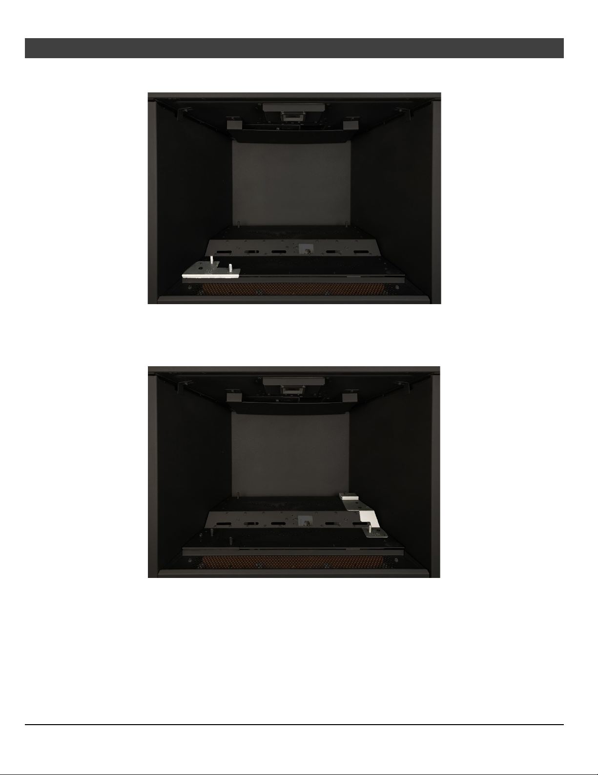
66 Optional Equipment (for qualified installers only)
3. Place the left log bracket on the lower-left corner of the burner as shown below. Secure the bracket to
the burner using one of the screws from the previous step.
4. Place the right log bracket on the lower-left corner of the burner as shown below. The upper portion of
the bracket fits over a stud attached to the burner. Secure the lower portion of the bracket to the
burner using one of the screws from step 2.
© Travis Industries 1/11/2021 - 1521 430 EG GSR2
Page 67
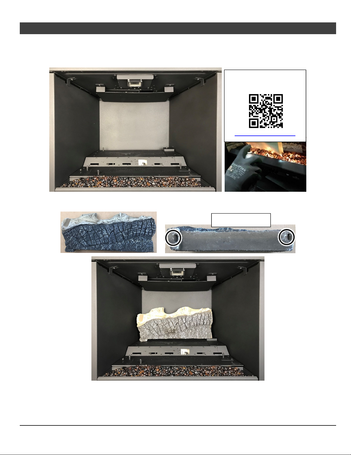
Optional Equipment (for qualified installers only)
5. Install the Ember glass, included with the insert, on the perforated area directly in front of the grate.
Place a thick layer of the ember glass over the perforations making sure to cover all of the holes.
Lightly dress the ember glass with the black touch-up paint provided. Check the appearance with the
lights on and add additional paint, as needed, for a realistic glowing ember appearance.
Scan this code with a QR
reader on your cell phone to
watch a video of the setup.
67
http://vimeo.com/289322734
6. Place Log #1 as shown below. The two slots on the bottom of the log sit over the pins on the burner.
With the rear log in place, push it all the way back
Bottom View of Log
© Travis Industries 1/11/2021 - 1521 430 EG GSR2
Page 68
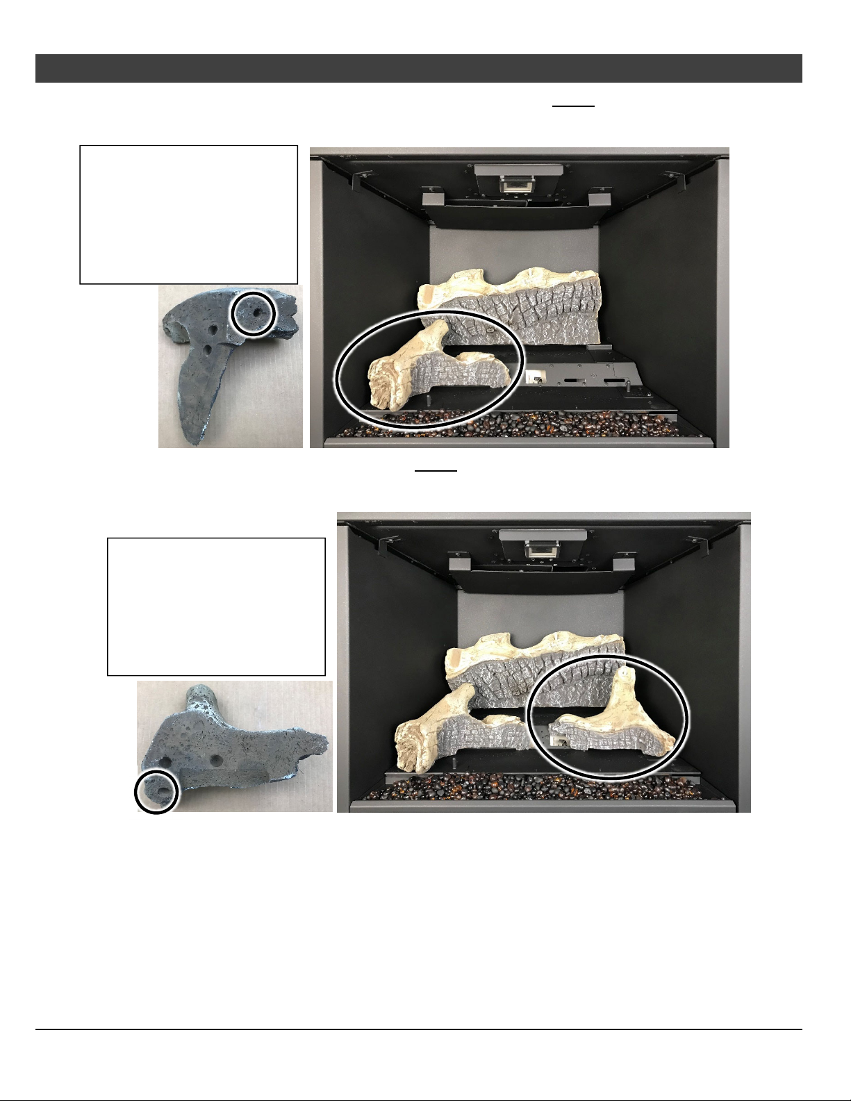
68
g
g
Optional Equipment
7. Place Log #4 on the lower front portion of the burner. The hole on the bottom of the Log #4 sits over
the far left pin on the left log bracket. Push the right end of Log #4 until it contacts the middle, sloped
portion of the burner.
There are 3 holes on the
underside of this log, 2 on the
back and 1 on the bottom. The
2 holes on the back are
clearance holes allowing proper
fitment over screw heads. The
hole on the bottom fits over the
stud on the lo
8. Place Log #6 as shown below. The hole on the bottom of the Log #6 sits over the front pin on the right
log bracket. Push the left end of the log backward until it is in contact with the sloped area between
the front and rear burner.
bracket.
(for qualified installers only)
There are 3 holes on the
underside of this log, 2 on the
back and 1 on the bottom. The
2 holes on the back are
clearance holes allowing proper
fitment over screw heads. The
hole on the bottom fits over the
stud on the lo
bracket.
© Travis Industries 1/11/2021 - 1521 430 EG GSR2
Page 69
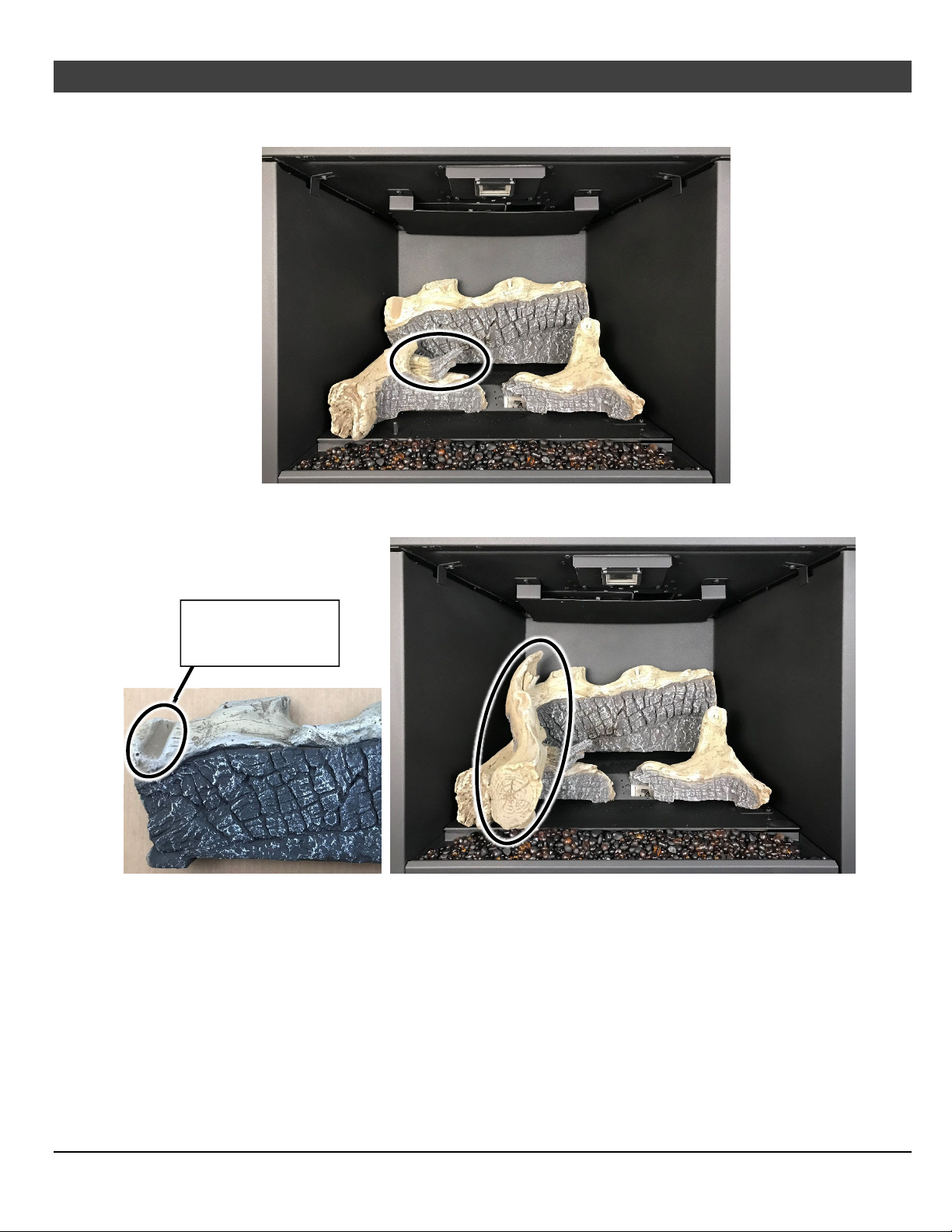
Optional Equipment (for qualified installers only)
9. Place Log #3 on the groove on top of Log #4 as shown below. The log should be pushed all the way
back until it contacts the rear log and rotated to the right so the charred tip of the log points to the center.
10. Place Log #2 as shown below. The hole on the bottom of Log #2 fits over the pin on the left log bracket.
The top edge of Log #2 rests in a groove on the left end of Log #1 and should be pushed all the way back.
69
Top edge of Log #2
rests in this groove
on Log #1.
© Travis Industries 1/11/2021 - 1521 430 EG GSR2
Page 70
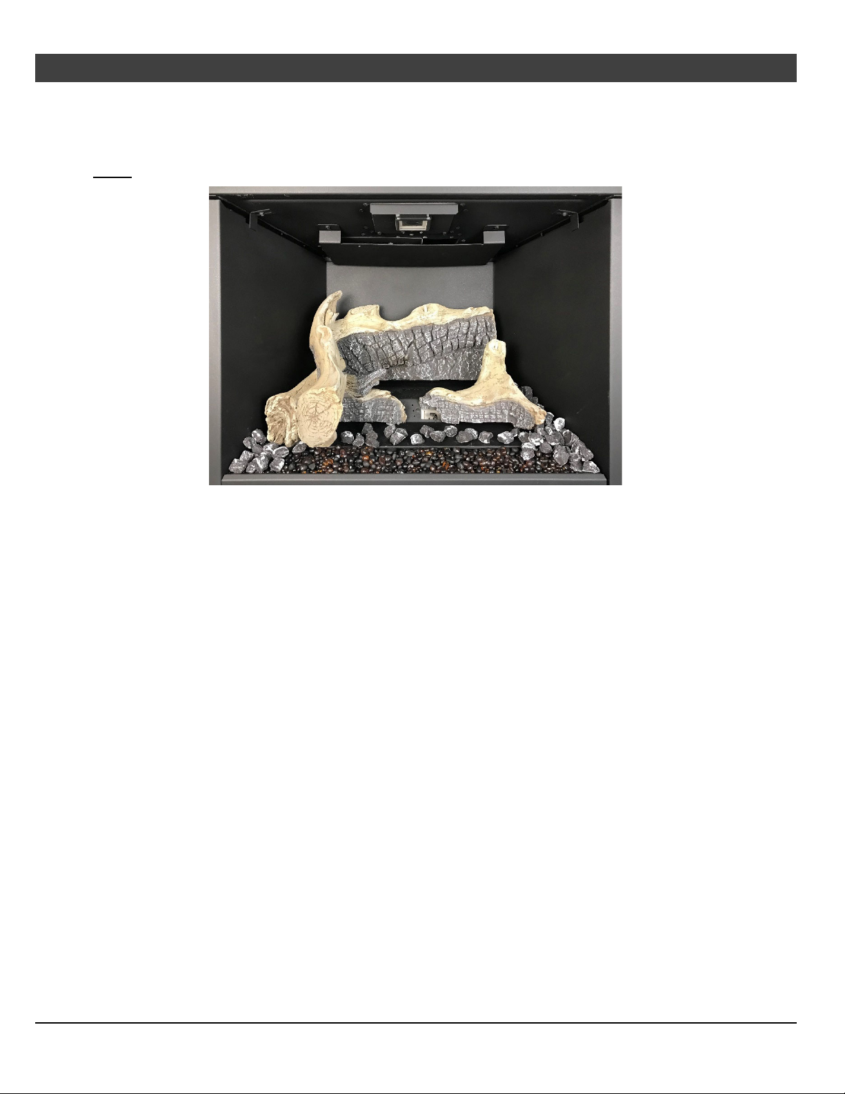
70 Optional Equipment (for qualified installers only)
11. Detail the firebox with ember chunks as shown below. The chunks may be placed on any exposed
metal floor surface on the lower burner and at either end of the Ember-Glo™ glass platform. Make
sure the ember chunks are placed well away from burner holes to ensure they do not create any flame
impingement.
NOTE: Save some ember chunks for final detailing of the firebox
© Travis Industries 1/11/2021 - 1521 430 EG GSR2
Page 71
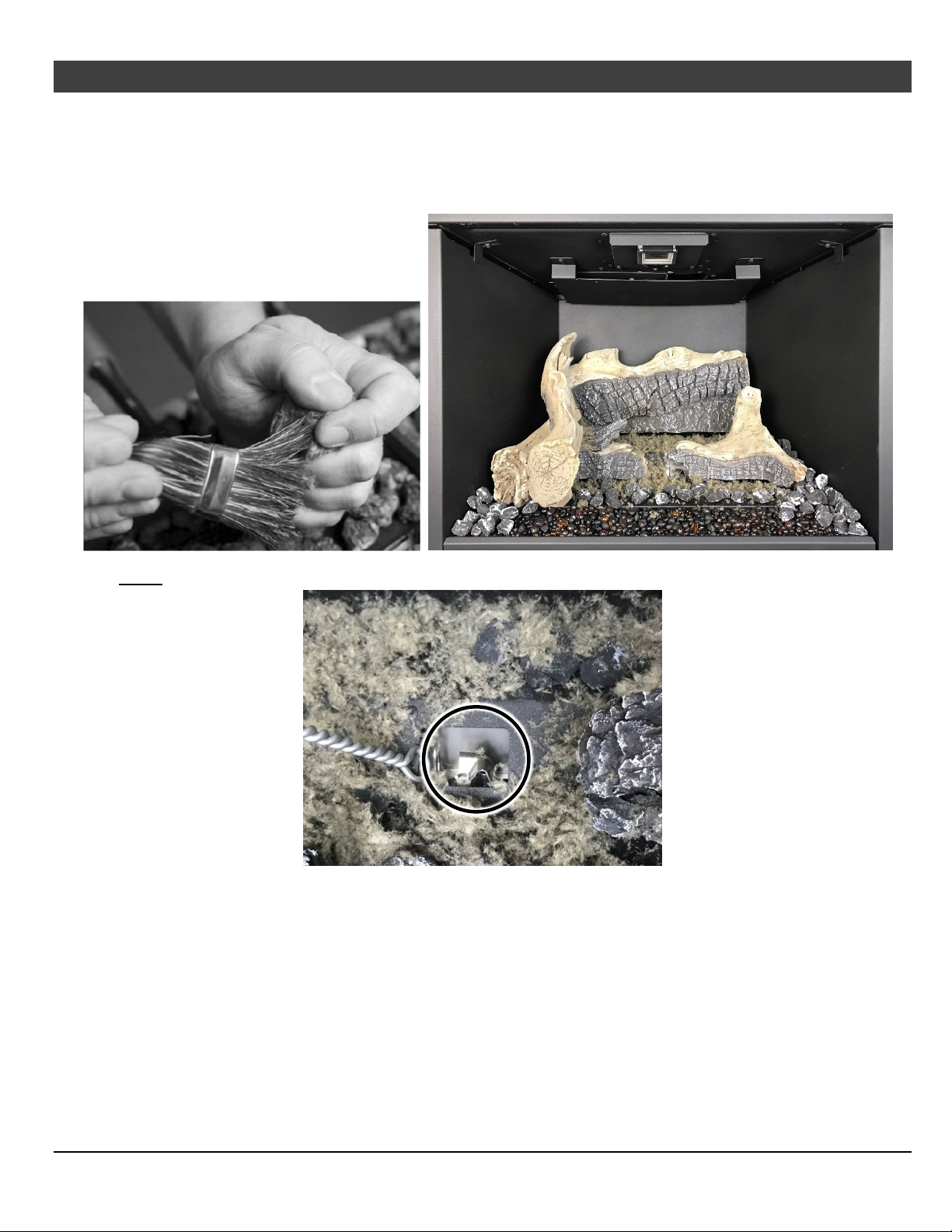
Optional Equipment (for qualified installers only)
12. Detail the top and bottom burner with Rock Wool. The included rock wool is placed on top of the
burner to enhance the glow from the burner. The rockwool can be applied in a relatively thick
layer. The best method for applying the rock wool is to brush it on to the burner. Compress a clump of
rockwool between your thumb and forefinger. Use a stiff brush to apply rockwool fibers onto the
burner. Do not use the entire bag of rockwool. Use only a small amount and save the remainder. Overuse of rockwool will diminish the glow and may cause sooting or other adverse conditions.
71
NOTE: Remove all rockwool from the pilot area (see below).
© Travis Industries 1/11/2021 - 1521 430 EG GSR2
Page 72
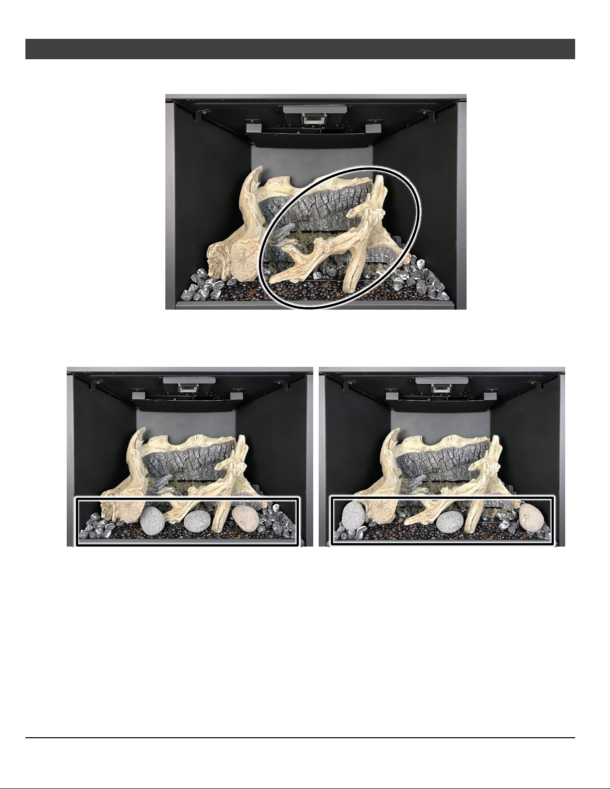
72
Optional Equipment
13. Place Log #5 as shown below. The slot on the bottom of Log #5 fits over the pin on Log#6. The left end
of the log rests on the Ember-Glo glass. Wiggle the log to seat the left end of the log into the glass.
14. Place (3) of the large stones on the Ember-Glo glass. There is no set placement for the large stones.
Place them anywhere on the ember-glass bed as long as placement does not interfere with log
placement, installing the glass frame assembly or encroaches on the burner creating flame
impingement.
(for qualified installers only)
© Travis Industries 1/11/2021 - 1521 430 EG GSR2
Page 73
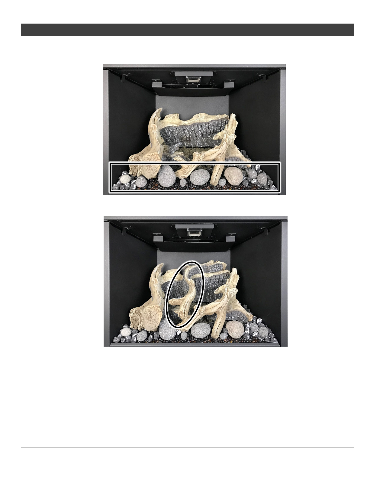
Optional Equipment (for qualified installers only)
15. Place the small stones wherever is aesthetically pleasing on the ember-glass bed and on top of the
ember chunks. Feel free to be creative in the stone placement, however, do not place the stones on
the burner surface.
16. Place Log #7 as shown below. The hole on the bottom of the Log #7 sits on the pin on the Log #1.
The lower end of Log #7 rests on the far left branch of Log #5.
73
17. Add any additional ember chunks and rockwool needed to create a realistic appearance.
18. Return the insert to its proper configuration.
© Travis Industries 1/11/2021 - 1521 430 EG GSR2
Page 74
74
Index
Accent Light Replacement ............................... 39
Additional Items Required .................................. 8
Air Shutter Adjustment ..................................... 27
Altitude Considerations .................................... 19
Battery Replacement ........................................ 37
Before You Begin ............................................. 29
Burner Removal ............................................... 28
Child-Proof Feature .......................................... 38
Clearances ....................................................... 11
Continuous/Intermittent Pilot Switch ................ 32
Dimensions ........................................................ 7
Direct Operation ............................................... 31
Display Fahrenheit or Celsius .......................... 36
Electrical Requirements ................................... 14
Electrical Specifications (for blowers) ................ 7
Ember-Glo Bulb Replacement ......................... 40
Exhaust Restrictor Settings .............................. 22
Factory Built Fireplace Hearth Requirements .. 10
Features ............................................................. 7
Fireplace Requirements ..................................... 9
Fuel .................................................................... 7
Gas Line Installation ......................................... 16
Gas Line Requirements ................................... 15
Glass Frame Removal and Installation ............ 25
Heating Specifications ........................................ 7
Important Information ......................................... 2
Installation Options ............................................. 7
Installation Warnings ......................................... 8
Introduction ........................................................ 2
Leveling Bolts ................................................... 13
Listing Details ..................................................... 2
Location of Controls ......................................... 31
Low Battery Indicator ....................................... 37
LP Conversion Instructions .............................. 47
Maintaining Your Heater's Appearance ........... 39
Masonry Fireplace Hearth Requirements .......... 9
Normal Operating Odors .................................. 38
Normal Operating Sounds ............................... 38
Order of Installation............................................ 8
Packing List ........................................................ 8
Power Outages ................................................ 37
Remote Control Warnings ............................... 29
Remote Operation ............................................ 33
Remote Set-Up ................................................ 30
Replacement Parts .......................................... 44
Starting the Heater for the First Time .............. 31
Steps for Finalizing the Installation .................. 26
Troubleshooting Table ..................................... 43
Vent Attachment – Tight Installations .............. 20
Vent Installation ............................................... 18
Vent Requirements .......................................... 17
Wiring Diagram ................................................ 44
Yearly Service Procedure ................................ 42
Want to know more?
Scan this code with a QR reader on
your cell phone or use the URL below to
watch a video of how to use the
GreenSmart® remote.
https://vimeo.com/84052701
© Travis Industries 1/11/2021 - 1521 430 EG GSR2
 Loading...