

Page 1

Pulsar
Pulsar
PulsarPulsar
ADSL PCI MODEM
User Manual – Linux
Revision 1.5
1
Page 2

CHAPTER 1: INTRODUCTION ....................................................................................................... 4
CHAPTER 2: HARDWARE INSTALLATION...................................................................................5
2.1 Connections, switches and LEDs...........................................................................................5
2.2 Installation .............................................................................................................................. 6
2.3 Filter Connections................................................................................................................... 7
3. Bridged Ethernet Setup (RFC 1483)............................................................................................8
3.1 Install Driver............................................................................................................................ 8
3.2 Load Driver.............................................................................................................................8
3.3 IP Addressing and Interface Up..............................................................................................9
4. PPPoE Setup (RFC 1483) ......................................................................................................... 10
4.1 Install Driver.......................................................................................................................... 10
4.2 Load Driver...........................................................................................................................10
4.3 Install PPPoE........................................................................................................................ 11
4.4 Configure PPPoE ................................................................................................................. 11
4.5 Interface Up.......................................................................................................................... 12
4.6 PPPoE Connect.................................................................................................................... 12
5. PPPoA Setup (RFC 2364) ......................................................................................................... 13
5.1 Install Driver.......................................................................................................................... 13
5.2 Create devices...................................................................................................................... 13
5.3 Load Driver...........................................................................................................................14
5.4 PPP Passwords.................................................................................................................... 14
5.5 PPPoA Dialup Profile............................................................................................................ 15
5.6 PPPoA Connect.................................................................................................................... 15
APPENDIX A – ISP Atm Parameters (Vpi / Vci)............................................................................ 16
APPENDIX B – Troubleshooting....................................................................................................17
B.1 Loading Modules.................................................................................................................. 17
B.2 Line Sync..............................................................................................................................18
B.3 TX and RX packets.............................................................................................................. 18
B.4 LCP timeouts (PPPoE and PPPoA only).............................................................................. 18
B.5 Authentication Failure (PPPoE and PPPoA only) ................................................................ 18
APPENDIX C – ATM Encapsulation options.................................................................................. 19
APPENDIX D – Technical Support and Warranty.......................................................................... 20
D.1 Technical Support................................................................................................................20
D.2 Returning a Product.............................................................................................................20
D.3 Warranty Terms you should know....................................................................................... 21
D.4 Limited Warranty..................................................................................................................21
D.5 Copyright.............................................................................................................................. 22
2
Page 3

WARNING : This product may only be connected to the Telecommunications Network
under the following conditions :
(i) The ADSL modem card can only be installed in a Computer that has a c ase (cover) fitted that
can only be removed with the use of a tool or key. The card should not be installed in a Computer
with a “Flip Top” case.
(ii) Do not connect the ADSL modem c ar d to the T elec ommunications Network until the Computer
case is fitted and screwed or locked in place.
(iii) In the event that the Computer case is to be removed, the ADSL Modem card must be
disconnected from the Telecommunications Network before the case is removed, and must not
be re-connected until the case is replaced and screwed or locked in place.
3
Page 4

CHAPTER 1: INTRODUCTION
Features
• PCI PLUG and PLAY. No jumpers or switches.
• Supports BT, Telstra, Nextep and RequestDSL ADSL Lines
• Downstream data rates upto 8Mbps
• Upstream data rates upto 1Mbps
• Supports Bridged Ethernet, PPPoE and PPPoA protocols
• Linux Kernel 2.2 and 2.4 drivers
Packing List
You should find the following items in your Pulsar ADSL modem kit:
• Pulsar PCI ADSL modem card
• Distribution CD, including drivers and documentation files
• A 2 metre RJ-11 phone cable
Please contact your dealer if any items are damaged or missing.
Trademarks
Pulsar ADSL is a registered trademark of Traverse Technologies Australia Pty Ltd. All other
trademarks and copyrights are the property of their respective holders.
Introduction
This manual provides step-by-step instructions for installing and setting up the Pulsar ADSL
modem to connect to the Internet. Once installed your ASDL modem will give you high speed
access to the internet, and this connection can also be shared to allow other users on your
network to share the same internet connection.
ADSL provides fast, reliable internet connec tivity that is always on, so you don’t need to dial up.
You can remain connected 24 hours a day and still use your phone line as you normally would.
4
Page 5
CHAPTER 2: HARDWARE INSTALLATION
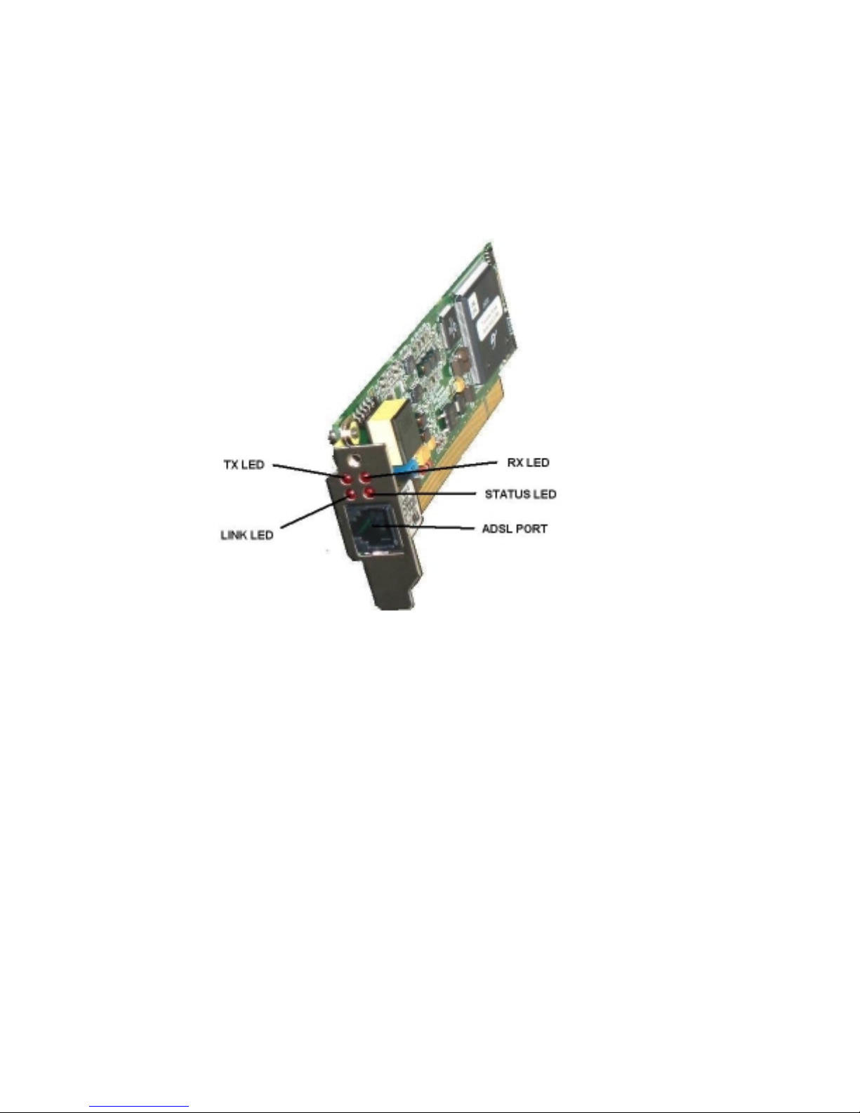
2.1 Connections, switches and LEDs
TX LED
This indicates transmit data activity
RX LED
This indicates receive data activity
LINK LED
This indicates that the Modem has finished training and achieved line synchronisation. During
training this LED will flash.
STATUS LED
This indicates that the Modem has DC power and the driver is correctly loaded.
ADSL Port
Connect this port to your ADSL line
5
Page 6

2.2 Installation
(i) Power OFF your computer system.
(ii) Remove screws and case.
(iii) Locate a free PCI slot.
(iv) Unscrew/remove slot rear panel.
(v) Place the ADSL Modem card over the PCI slot. Press the Modem c ard down firmly with both
hands into the slot. Check to be sure that the Modem card is seated property in the PCI slot.
(vi) Screw/secure rear panel of ADSL Modem card.
(vii) Refit case and screws.
(viii) Plug one end of the RJ11 cable that came with your ADSL modem into the sock et on the
modem and plug the other end into your ADSL line socket.
6
Page 7
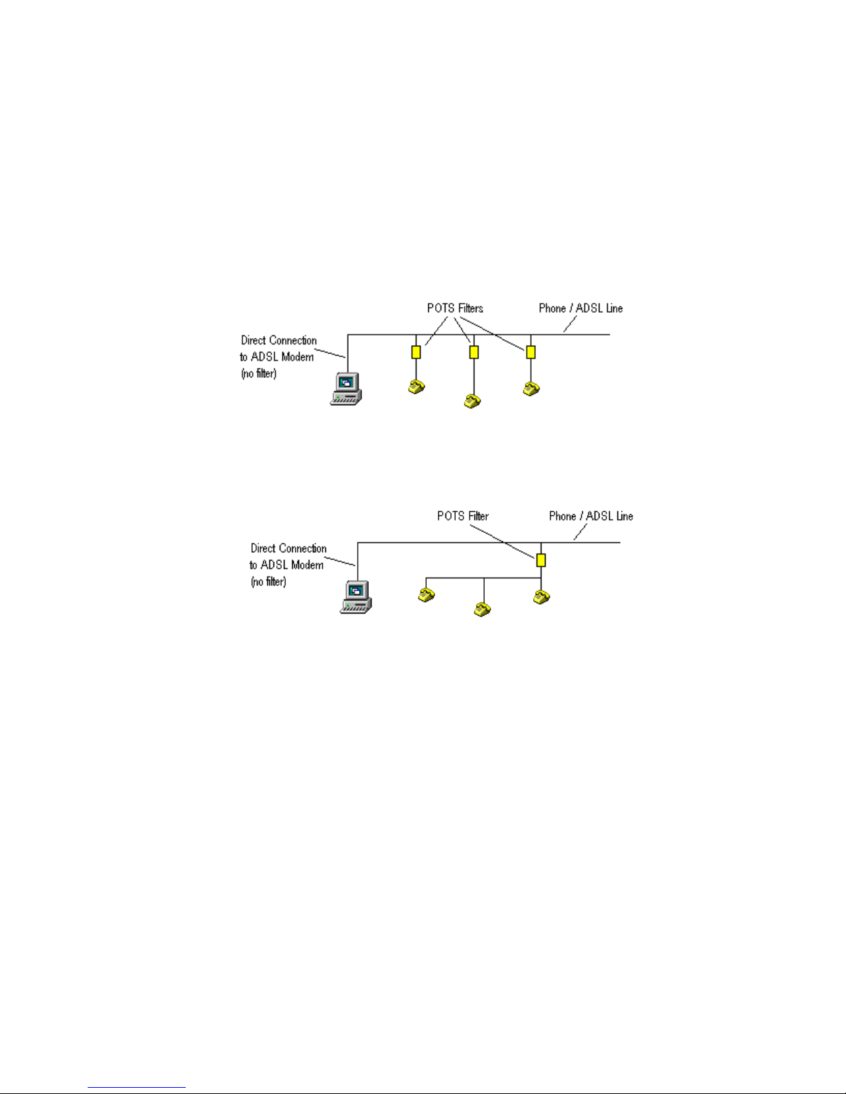
2.3 Filter Connections
If your ADSL connection is also used by POTS (Plain Old Telephone System) devices s uch as
phones, fax machines and answering machines, they must be filtered to prevent them from
interfering with your ADSL connection.
The diagram below shows how POTS filters can be connected
It is also possible for several POTS devices to share the same filter
Important : DO NOT place a POTS filter in line between your ADSL modem and the Phone /
ADSL line.
7
Page 8

3. Bridged Ethernet Setup (RFC 1483)
3.1 Install Driver
(i) Firstly load the driver from your Pulsar distribution CD or from the Tr averse website. The linux
drivers are located under the /linux subdire ctory on the CD. There are s everal subdirec tories for a
range of Linux kernels. For example the subdirectory
/linux/drivers/3.2.1/redhat7.3
Contains the RedHat 7.3 driver tarball called pulsar.tgz for version 3.2.1 of the driver. Copy this
onto your hard drive.
Alternatively you can compile a driver for any 2.4 kernel by using the driver engine at...
http://adsl4linux.no-ip.org
(ii) Untar the module from the tarball
tar -xvzf pulsar.tgz
(iii) move the driver to /lib/modules
mv pulsar.o /lib/modules
3.2 Load Driver
Load the module with the appropriate Vpi / Vci values
insmod /lib/modules/pulsar.o Rfc1483Mode=0 Rfc1483Vpi=8 Rfc1483Vci=35 GtiTrellis=0
Important : for a list of Vpi/Vci values for different providers (ISPs) r efer to Appendix A
Hint : if you can’t find a driver for your ker nel, try the following …
(a) Use the closest match and add the –f option when loading the module (2.2 kernels only)…
insmod –f /lib/modules/pulsar.o Rfc1483Mode=0 Rfc1483Vpi=8 Rfc1483Vci=35 GtiTrellis=0
(b) Use the Driver Engine at http://adsl4linux.no-ip.org to compile a driver for your kernel (2.4
kernels only)
Once the driver has been loaded, line sync should be obtained within about 30 seconds. The Line
Sync LED on the rear panel indicates the current state of the line.
8
Page 9

3.3 IP Addressing and Interface Up
(i) When your ADSL line is provisioned your ISP should provide you with an IP address (normally
public) and a gateway address. Once your driver is loaded you can bring up the interface
ifconfig 203.22.33.44 eth1 up
The above example shows a Public IP address of
Note : The Pulsar will be eth1 if you already have an ethernet card installed. Otherwise it
will be eth0. You can double check this in /var/log/messages
Oct 7 12:17:51 firewall kernel: pulsar0: GSI ADSL, eth1, ttyG/cug, 00:0A:FA:02:80:14
IRQ:10 Address:0xE8800000
(ii) Now add a route to your ISPs gateway
router add default gw 203.22.33.1 eth1
The above example shows a gateway address of
You should now be able to ping the gateway address, and addresses by number on the internet
ping 198.182.196.56
(iii) Now configure your DNS settings. Add your ISPs DNS settings to the /etc/resolv.conf file
nameserver 203.22.5.2
nameserver 203.22.5.3
The above example shows a primary DNS of 203.22.5.2 and a secondary DNS of 203.22.5.3
You should now be able to ping addresses by name on the internet
203.22.33.44
203.22.33.1
ping www.linux.org
9
Page 10

4. PPPoE Setup (RFC 1483)
4.1 Install Driver
(i) Firstly load the driver from your Pulsar distribution CD or from the Tr averse website. The linux
drivers are located under the /linux subdire ctory on the CD. There are s everal subdirec tories for a
range of Linux kernels. For example …
/linux/drivers/3.2.1/redhat7.3
Contains the RedHat 7.3 driver tarball called pulsar.tgz for version 3.2.1 of the driver. Copy this
onto your hard drive.
Alternatively you can compile a driver for any 2.4 kernel by using the driver engine at...
http://adsl4linux.no-ip.org
(ii) Untar the module from the tarball
tar -xvzf pulsar.tgz
(iii) move the driver to /lib/modules
mv pulsar.o /lib/modules
4.2 Load Driver
Load the module with the appropriate Vpi / Vci values
insmod /lib/modules/pulsar.o Rfc1483Mode=0 Rfc1483Vpi=8 Rfc1483Vci=35 GtiTrellis=0
Important : for a list of Vpi/Vci values for different providers (ISPs) r efer to Appendix A
Hint : if you can’t find a driver for your ker nel, try the following …
(a) Use the closest match and add the –f option when loading the module (2.2 kernels only)…
insmod –f /lib/modules/pulsar.o Rfc1483Mode=0 Rfc1483Vpi=8 Rfc1483Vci=35 GtiTrellis=0
(b) Use the Driver Engine at http://adsl4linux.no-ip.org to compile a driver for your kernel (2.4
kernels only)
Once the driver has been loaded, line sync should be obtained within about 30 seconds. The Line
Sync LED on the rear panel indicates the current state of the line.
10
Page 11

4.3 Install PPPoE
There are two popular methods for running PPPoE under Linux
- Use the PPPoE support in the kernel
- Use the Roaring Penguin PPPoE client
Roaring Penguin is the easiest method so it is described here. However exper ienced users will
want to use the PPPoE support in the kernel. In this case refer to the Linux DSL howto at …
http://www.tldp.org/HOWTO/DSL-HOWTO/index.html
Important : Problems have been reported with Roaring Penguin V3.5-1 and Debian
Distributions. Debian users should use pppoeconf instead.
(i) Download Roaring Penguin PPPoE (RP-PPPoE)
Firstly download a copy of RP-PPPoE from
http://www.roaringpenguin.com/pppoe/#download
Important : Your distribution may already includ e RP-PPPoE, however if it is earlier than
V3.5-1 you should upgrade it
(ii) Install RP-PPPoE
rpm –i rp-pppoe-3.5-1.i386.rpm
If your distribution doesn’t support RPMs then perform a source install
tar xvfz rp-pppoe-3.5.tar.gz
cd rp-pppoe-3.5
./go
4.4 Configure PPPoE
Now run the RP-PPPoE configuration utility
adsl-setup
Answer all questions as prompted.
Note : The Pulsar will be eth1 if you already have an ethernet card installed. Otherwise it
will be eth0. You can double check this in /var/log/messages
Oct 7 12:17:51 firewall kernel: pulsar0: GSI ADSL, eth1, ttyG/cug, 00:0A:FA:02:80:14
IRQ:10 Address:0xE8800000
11
Page 12

4.5 Interface Up
When your driver is loaded you can bring up the interface
ifconfig eth1 up
4.6 PPPoE Connect
Now start RP-PPPoE
adsl-start
After a few seconds you should see the connected message. If this doesn’t occur, and RP- PPPoE
times out, refer to Appendix B Troubleshooting.
12
Page 13

5. PPPoA Setup (RFC 2364)
5.1 Install Driver
(i) Firstly load the driver from your Pulsar distribution CD or from the Tr averse website. The linux
drivers are located under the /linux subdire ctory on the CD. There are s everal subdirec tories for a
range of Linux kernels. For example …
/linux/drivers/3.2.1/redhat7.3
Contains the RedHat 7.3 driver tarball called pulsar.tgz for version 3.2.1 of the driver. Copy this
onto your hard drive.
Alternatively you can compile a driver for any 2.4 kernel by using the driver engine at...
http://adsl4linux.no-ip.org
(ii) Untar the module from the tarball
tar -xvzf pulsar.tgz
(iii) move the driver to /lib/modules
mv pulsar.o /lib/modules
5.2 Create devices
The Pulsar driver provides a tty interface f or PPPoA. You need to create the f ollowing devices for
PPPoA
mknod /dev/ttyG0 c 43 0
chown root.nobody /dev/ttyG0
chmod 0660 /dev/ttyG0
mknod /dev/cug0 c 44 0
chown root.nobody /dev/cug0
chmod 0660 /dev/cug0
13
Page 14

5.3 Load Driver
Load the module with the appropriate Vpi / Vci values
insmod /lib/modules/pulsar.o Rfc2364Mode=0 Rfc2364Vpi=0 Rfc2364Vci=38 GtiTrellis=0
Important : for a list of Vpi/Vci values for different providers (ISPs) r efer to Appendix A
Hint : if you can’t find a driver for your ker nel, try the following …
(a) Use the closest match and add the –f option when loading the module (2.2 kernels only)…
insmod /lib/modules/pulsar.o Rfc2364Mode=0 Rfc2364Vpi=0 Rfc2364Vci=38 GtiTrellis=0
(b) Use the Driver Engine at http://adsl4linux.no-ip.org to compile a driver for your kernel (2.4
kernels only)
Once the driver has been loaded, line sync should be obtained within about 30 seconds. The Line
Sync LED on the rear panel indicates the current state of the line.
5.4 PPP Passwords
Passwords for ppp dialup connections are stored in the following files
/etc/ppp/chap-secrets
/etc/ppp/pap-secrets
If you are unsure which protocol your ISP requires, set up both files the same.
Shown below is an example of a secrets file…
# client server secret
fred * flintstone
This example shows the following user account:
Username: fred Password: flintstone
Note that the server entry should always be a wildcard “*”.
14
Page 15

5.5 PPPoA Dialup Profile
Next Create a ppp dialup profile. Create a f ile called
options
user "fred"
ttyG0
sync
persist
/etc/ppp/peers/adsl
containing the following
5.6 PPPoA Connect
The following command invokes pppd using the adsl profile created above
pppd call adsl
Now run a tail on /var/log/messages and hopefully you w ill see something like the following
tail –f /var/log/messages
Oct 15 10:21:13 rh73 pppd[1442]: pppd 2.4.1 started by root, uid 0
Oct 15 10:21:13 rh73 pppd[1442]: Using interface ppp0
Oct 15 10:21:13 rh73 pppd[1442]: Connect: ppp0 <--> /dev/ttyG0
Oct 15 10:21:13 rh73 /etc/hotplug/net.agent: assuming ppp0 is already up
Oct 15 10:21:13 rh73 pppd[1442]: local IP address 192.168.1.2
Oct 15 10:21:13 rh73 pppd[1442]: remote IP address 192.168.1.1
15
Page 16

APPENDIX A – ISP Atm Parameters (Vpi / Vci)
Country Provider ATM
Protocol
.au Telstra PPPoE
or Bridged Eth.
.au Nextep Bridged Eth. 1 32
Austria AON PPPoA 8 48
.be Belgacom PPPoE
or Bridged Eth.
.bh Batelco PPPoA 8 35
.ch Sunrise and
Bluewin
.fr Wannadoo PPPoA or
.nl PPPoA 8 48
.nz
.pt Portugal Telecom PPPoE
.uk British Telecom PPPoA 0 38
USA ---- PPPoA 8 35
***NOTE
move the LAN PVC elsewhere. eg.
insmod /lib/modules/pulsar.o Rfc2364Mode=0 Rfc2364Vpi=0 Rfc2364Vci=100 Rfc1483Vpi=1
GtiTrellis=0
NZ Telecom
: 0/100 is also the default LAN PVC so to use a W AN (PPPoA) PVC or 0/100 you must
***
PPPoE 8 35
PPPoE
PPPoA 0 100
or Bridged Eth.
VPI VCI
835
835
835
035
This sets the LAN VPI to 1/100 and the WAN VPI to 0/100.
16
Page 17

APPENDIX B – Troubleshooting
B.1 Loading Modules
If the module loads without error messages, you should see the following in response to the
lsmod
command…
Module Size Used by
pulsar 252410 0 (unused)
You will probably also see several other kernel modules loaded.
You should also see the following at the end of the
Oct 7 12:17:51 firewall kernel: pulsar: Traverse Pulsar ADSL pulsar.o v3.1.2 1-Oct-2002
Oct 7 12:17:51 firewall kernel: pulsar: powered by GlobespanVirata ADSL Firmware
Version: S6118
Oct 7 12:17:51 firewall kernel: GpAdapterInit - StartRFC1483_MODE_BRIDGED_ETH_LLC
Oct 7 12:17:51 firewall kernel: pAdapter->AtmUniHandle c75ed000
Oct 7 12:17:51 firewall kernel: pAdapter c6332000
Oct 7 12:17:51 firewall kernel: pulsar0: GSI ADSL, eth1, ttyG/cug, 00:0A:FA:02:80:14
IRQ:10 Address:0xE8800000
If the driver fails to load, use the
been detected by the bios. In amongst the other PCI devices on you machine you should see…
Bus 0, device 14, function 0:
Network controller: Unknown vendor Unknown device (rev 1).
Vendor id=14bc. Device id=d002.
Slow devsel. Fast back-to-back capable. IRQ 10. Master Capable. Latency=32. Min
Gnt=3.Max Lat=200.
Non-prefetchable 32 bit memory at 0xe8800000 [0xe8800000].
Note : the addresses, bus number and device number will vary from machine to machine.
If the ADSL card is not listed, then you should check to s ee that the c ard is s eated c orrec tly in it’s
PCI slot. You can also try another slot. Also check the edge connector on the card for signs of dirt,
pizza finger prints or contamination. The edge connector can be cleaned by using an abrasive
pencil eraser, then wipe it with a clean cloth dipped in Metholated Spirits.
cat /proc/pci
/var/log/messages
command to chec k to see if your ADSL card has
file…
17
Page 18

B.2 Line Sync
Once you have loaded the pulsar model, you should obtain line sync within about 30 seconds.
Once line sync has been obtained you will see this logged in
Oct 7 12:22:59 firewall kernel: pulsar0: Link established (512/128)
You should also see the Line Sync LED come on. If this doesn’t occur check the connection
between your ADSL modem and the line socket on the wall. Also try disconnecting all other device
such as phones, answering machines and fax machines from the line.
Hint : If you have other devices sharing your ADSL line they must be connected via a filter
or splitter to prevent them from interfering with your ADSL service.
/var/log/messages
…
B.3 TX and RX packets
If you are using Bridged Ethernet or PPPoE you can use the
packets are being sent and received. If you so that pack ets are being sent, but none are received
check your ATM settings. Do you have the correct VPI and VCI f or your provider? See Appendix
A.
ifconfig
command to check if
B.4 LCP timeouts (PPPoE and PPPoA only)
Check /var/log/messages for LCP timeouts. These are often caused by incorrect ATM settings.
Check your VPI and VCI values against the table in Appendix A.
B.5 Authentication Failure (PPPoE and PPPoA only)
Check your username and password in the following files
/etc/ppp/chap-secrets
/etc/ppp/pap-secrets
Note : Some providers require an @provider in the username, eg.
mickey@bigpond
or
minnie@bt
18
Page 19

APPENDIX C – ATM Encapsulation opti ons
Other ATM encapsulation methods are also supported. The encapsulation method is configured
when the driver is loaded. For example
Rfc1483Mode=0 (Bridged Ethernet)
or
Rfc2364Mode=0 (PPPoA with VC Encapsulation)
A list of all modes is shown below...
RFC1483
RFC1483_MODE_BRIDGED_ETH_LLC = 0, (default)
RFC1483_MODE_BRIDGED_ETH_VC = 1,
RFC1483_MODE_ROUTED_IP_LLC = 2,
RFC1483_MODE_ROUTED_IP_VC = 3,
RFC1483_MODE_RFC1577_ENCAP = 4
RFC2364
RFC2364_MODE_VC = 0, (default)
RFC2364_MODE_LLC = 1
19
Page 20

APPENDIX D – Techni cal Support and Warranty
D.1 Technical Support
If you encounter problems with your Pulsar ADSL Modem, and you cannot locate the problem,
firstly contact the dealer where you purchased your modem. If your dealer is unable to help you
then contact:
Traverse Technologies Australia Pty Ltd.
652 Smith St
Clifton Hill
Vic 3068
Internet: http://www.traverse.com.au
support@traverse.com.au
D.2 Returning a Product
If Technical Support determ ines that you need to return the product for warranty repair service,
you will be issued a Return Authorisation (RA) number.
Return Authorisation Guidelines:
1. No product will be accepted for return f or warranty service unless accompanied by a valid RA
number. No RA number will be issued without a valid serial number. Write the RA number
clearly on the outside of the package as follows: “RA#Annnn”.
2. Keep a record of the RA number and the nam e of the service representative who issued you
the RA number for future reference.
3. Return a copy of the original sales invoice for proof of purchase and verification of warranty.
4. If it is determined that your warranty has expired or that the problem is not covered by the
warranty, a method of payment will have to be authorised before an RA number is issued.
5. Write your nam e, return address and RA number on a sm all strip of paper and tape it to the
ADSL Modem before packing it
6. Write a note describing the problem giving as much detail as possible.
7. Place the modem in the original packaging, then in padded shipping bag. Use protective
material, such as bubble wrap or foam to further protect the modem.
8. The RA number that is issued to you is valid for only thirty days after the date of issue.
9. We will not accept packages that are not prepaid for shipping charges. W e will not accept
COD shipments for shipping costs.
20
Page 21

10. The shipping address:
Traverse Technologies Australia Pty Ltd
Technical Support
652 Smith St
Clifton Hill
Vic 3068, Australia
If you drop off a product at the above address, it will be processed and returned as a normal RA.
Please do not expect to be given a replacement right away, while you wait.
D.3 Warranty Terms you should know
Warr anty Repair: Traverse Tec hnologies Australia Pty Ltd will repair or replace (at our option)
free of charge, within the warranty period. W e require you to furnish a receipt, or similar bill of
sale to determine the date of purchas e. If you do not supply an adequate proof of pur chase with
the product, you will be charged an out-of-warranty repair fee, determined by the value of labor
plus materials.
Shipping: For products under warranty, you must pay one way shipping and we will cover the
shipping charges when we return the product to you. We cover the return charges within
Australia. We do not provide express, or next day shipment of pr oducts. You will be required to
pay for any next day shipping, or special handling you require. We will ship back to you by the
most economical way, eg. Express Post. Replacement goods will not be shipped until the
returned unit is received.
D.4 Limited Warranty
Our company warrants this product against defects in materials and workm anship for a period of
one (1) year from the date of purchase. Dur ing the warranty period, products determined by us to
be defective in form or function will be repaired, or at our option, replaced at no charge. This
warranty does not apply if the product has been damaged by accident, abuse, m isuse, missing
serial number, or force majeure (such as a lightning strike), or as a result of service or
modification other than by Traverse Technologies Australia Pty. Ltd.
This warranty applies only to the original purchaser of the Pulsar ADSL Modem, and is nontransferable. The warranty does not cover any parts not installed by Traverse Technologies
Australia Pty. Ltd. This warranty is limited to parts and labor only and does not include any
incidental that may occur during the course of service including (but not limited to) shipping,
delivery, etc. Any incidental charges that may occur are the responsibility of the user.
Traverse Technologies Australia Pty. Ltd. is not responsible for any lost profits, lost savings or
other incidental or consequential damages arising out of the use of, or inability to use, this
product. This includes damage to property and, to the extent permitted by law, damages for
personal injury. This warranty is in lieu of all other warranties including implied warranties of
merchant ability and fitness for a particular purpose.
This warranty applies only to this product, and is governed by the laws of Australia.
21
Page 22

D.5 Copyright
Copyright © 2002
All rights reserved.
No part of this publication may be reproduced, stored in a retrieval system, or transmitted, in any
form by any means, electronic, mechanical, photocopying, recording, or otherwise, without the
prior written consent of Traverse Technologies Australia Pty. Ltd.
While reasonable efforts have been taken in the preparation of this manual to assure its
accuracy, the manufacturer and distributors assume no liability resulting from any errors or
omissions in this m anual, or from the use of the inf ormation contained herein. The infor mation
contained herein is subject to change without notice. Revisions may be issued to advise of such
changes and/or additions.
22
 Loading...