

Travel Vision R6 80 User Manual
www.travel-vision.com
USER MANUAL
BENUTZERANLEITUNG
GEBRUIKSAANWIJZING
(Page 2)
(Seite 20)
(Pagina 38)
Travel Vision R6 80 ®
EUROPE
Version 1.2 December 2014 from firmware 1.0.22

USER MANUAL
Introduction
Congratulations on the purchase of your Travel Vision R6 ® system.
This user manual provides all necessary information on the installation, operation and maintenance of your
system.
The Travel Vision R6 ® provides maximum freedom. For example, you can park your trailer or RV in the shadow
of a tree, position the system anywhere you like and fully enjoy your favorite television programs. The Travel
Vision R6 ® is set up in a snap, is very easy to operate and is connected to the system with a single cable. With
just a push of a button, the Travel Vision R6 ® automatically finds the satellite of your choosing. After the dish has
been aligned, you can easily remove the control module from the system for safe storage and continue watching
television without interruption.
Where possible, high quality materials such as stainless steel and durable plastics are used to ensure a long
service life. There are no parts in the device that require servicing by the user.
WARNINGS AND REMARKS
The contents of this manual are up to date at the time of print. In no way can TravelVision BV be held liable for
any errors that may occurred while writing this manual.
TravelVision BV reserves the right to implement any modifications it deems necessary during the development of
the products, and to modify or change this installation and user manual and the herein described products without
prior notice.
Travel Vision R6 ® is a registered trade mark of TravelVision BV.
Please first read this user manual before putting your Travel Vision R6 ® into operation. Follow all instructions
and carefully observe the directions presented in this manual.
Before taking the device into operation, first ensure that all cables have been connected correctly. Please note
that when you switch on the power supply and activate the satellite receiver, the satellite dish will begin rotating
within a few seconds. This is also indicated on the display of the control module.
Switch off and disconnect the power supply before you carry out any actions on the system. The control module is
splash-proof however it may not be cleaned with water.
Even without the control module, it is not recommended to clean the antenna with a high-pressure washer. Use a
soft and moist cloth with soap instead.
For additional information we kindly ask you to contact the specialist dealer where you purchased your system.
User manuals and software updates can be found on our website:
www.travel-vision.com
© Copyright 2014 TravelVision BV
Page
2

Table of contents
1.1 Safety instructions and warnings ...................................................................................................... 4
1.2 Tips before going on vacation ................................................................................................................... 4
1.3 Travel Vision R6 ® packaging ................................................................................................................... 4
1.4 Shipment check list Travel Vision R6 ®..................................................................................................... 4
1.5 Components of the Travel Vision R6 ® ..................................................................................................... 5
2.1 Control module .......................................................................................................................................... 6
3.1 Choosing a setup location ......................................................................................................................... 6
3.2 Positioning the tripod ................................................................................................................................. 6
3.3 Placing the antenna dish ........................................................................................................................... 7
3.4 Electric connection of the Travel Vision R6 ® ........................................................................................... 8
3.5 Searching satellite ..................................................................................................................................... 9
3.6 Special remarks on searching for satellite ............................................................................................... 12
3.7 Removing the control module .................................................................................................................. 13
4.1 Menu ....................................................................................................................................................... 14
5.1 Park position ........................................................................................................................................... 15
6.1 Stop button .............................................................................................................................................. 15
7.0 Error messages ....................................................................................................................................... 15
7.1 No satellite found, check manual ............................................................................................................ 15
7.2 Satellite found, but no picture .................................................................................................................. 15
7.3 Satellite found, but not all channels ......................................................................................................... 16
7.4 Error No 24V connected: ......................................................................................................................... 16
7.5 Error Low Voltage:................................................................................................................................... 16
7.6 Error during software update: .................................................................................................................. 16
7.7 Error during software update: .................................................................................................................. 16
7.8 Error during software update: .................................................................................................................. 16
7.9 Error messages: calibration failed, error azimuth adjustment, error elevation adjustment ...................... 16
8.0 No LNB signal: ........................................................................................................................................ 17
8.1 Error OXBAFF: ........................................................................................................................................ 17
8.2 Troubleshooting and frequently asked questions.....……………………………....................................…..17
9.1 Specifications .......................................................................................................................................... 19
10.1 Warranty conditions................................................................................................................................. 19
page 3

1.1 Safety instructions and warnings
Carefully read this user manual before using the device.
Scope of use
Your Travel Vision R6 ® has been developed to automatically search and find a satellite signal. This device is
only intended for use by consumers and outdoors
For safe use, please observe the following:
Tripod
When extending or folding up the tripod, be careful not to pinch your hands between the legs of the tripod.
Handling the dish unit
Use the hand grip on the back of the dish unit when picking up the system for positioning or storage.
LNB arm
When folding down the LNB arm, ensure that your fingers do not become pinched in the hinge.
During alignment
Make sure not come into physical contact with the dish unit while it is aligning and rotating. Only use the control
module and make sure nothing and nobody enters the turning circle of the system during its alignment.
Connecting the system
Always first fully connect the system before switching on the power supply. Otherwise you risk receiving a slight
electric shock.
Coaxial cable
Ensure that when unrolling the system’s coaxial cable, it is laid down as flat as possible and that it is covered so it
does not pose a tripping hazard.
1.2 Tips before going on vacation
Check whether your subscription or smartcard is still valid.
Check the correct function of the system.
Check the website www.travel-vision.com or ask your dealer for any software updates.
1.3 Travel Vision R6 ® packaging
The Travel Vision R6 ® is packed in a cardboard box .
Before opening the package we kindly request that you check the following:
• The cardboard box may not be deformed and may not have serious and obvious signs of damage such
as cracks in the cardboard or dents resulting from impact.
• The sealing tape on the package must be intact.
1.4 Shipment check list Travel Vision R6 ®
The following parts should be included in the shipment:
• Antenna dish (complete antenna unit with LNB)
• Control module (display, holder with electronics and motors)
• Tripod
• 15 meters of coaxial cable with waterproof connectors
• 230V power adapter
• Power inserter
• 20 cm coaxial cable (for the connection on the power inserter to the receiver)
• User manual
Page
4
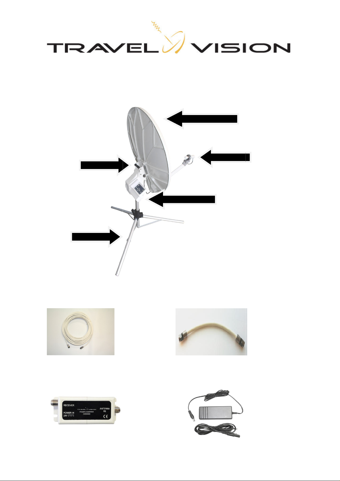
Components of the Travel
1.5
Vision R6 ®
Antenna dish
LNB
Bracket
Control module
Tripod
15m coaxial cable
20cm coaxial cable
Power inserter
230V power adapter
page 5
in motors and electronics drive the system
commands to the antenna dish, e.g. satellite choice, parking, etc…
the system’s status on the display
Replaces or updates
Choosing a setup location
be considered when deciding
surface on which the ante
The ideal location is a place where there is
is obstructed, choose a location with
satellite. This means that there should be no
After choosing a
sure that the legs are
and rigid
Place the tripod on a surface
to be perf
locate
search
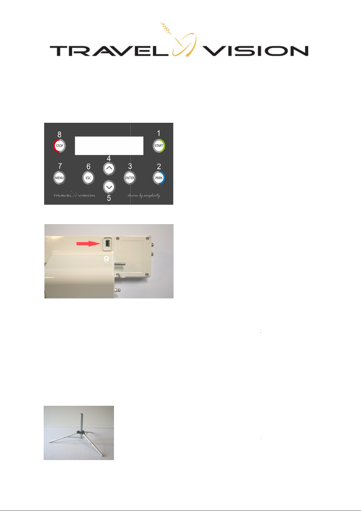
Park (system places itself in
A USB port is located at the back of the control
module to carry out software updates
how to update the software)
the location of where to set up the system:
in the direction of the desired
trees, trailers or RV’s
cation, you can unfold and position the tripod.
system will stand
the supplied pegs.
as flat as possible. The surface does not have
the unit is leveled, the quicker the system
2.1 Control module
The control module has 4 functions:
• Actuate The build-
• Control Sends
• Display indicates
• Update
the software
Control panel buttons:
1. Start (system starts
2.
3. Enter (select)
4. Arrow up
5. Arrow down
6. Escape (one step back)
7. Menu
8. Stop
9. USB port
ing for satellite)
the parked position)
3.1
Several factors must
• The
•
• When the view
3.2 Positioning the tripod
nna will be positioned should be reasonably flat.
En
position. The legs must be secured by means of
ectly horizontal, but the more
will
the satellite.
(see section 4.2 on
on
an unobstructed view in all directions.
an unobstructed view
obstructions such as
suitable setup lo
fully extended so that the
that is
, buildings, etc…
in a stable
Page
6
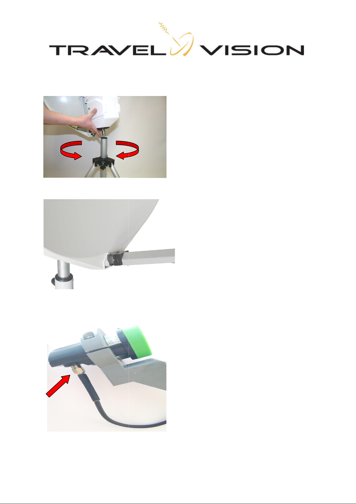
How to mount the antenna dish on the tripod:
of the antenna dish in
Then slowly rotate the dish in either direction until the axle
Lower the LNB arm all the way down. And tighten the
Before using the system, connect the cable with the F
tighten it
3.3 Placing the antenna dish
Guide the rotation axle
socket of the tripod
has been fixed in the tripod.
to the plastic
screw
connector to the LNB and handrequired.
. No tools are
page 7
3.4 Electric connection of the Travel Vision R6 ®
The system is connected with 2 coaxial cables. The long coaxial cable is mounted between the antenna unit
located outside and the power inserter located inside. The power inserter is connected to your receiver by means
of the short coaxial cable (receiver is not included).
The Travel Vision R6 ® operates on 24 volt. The required 24 volt is supplied by the power inserter with 12V power
adapter.
By default, The Travel Vision R6 ® is suited for 1 receiver with unlimited channel reception from the chosen
satellite.
R6
Connection procedure:
Switch on your satellite receiver to provide the LNB with power.
The system is now ready for use.
Coax
Power Inserter
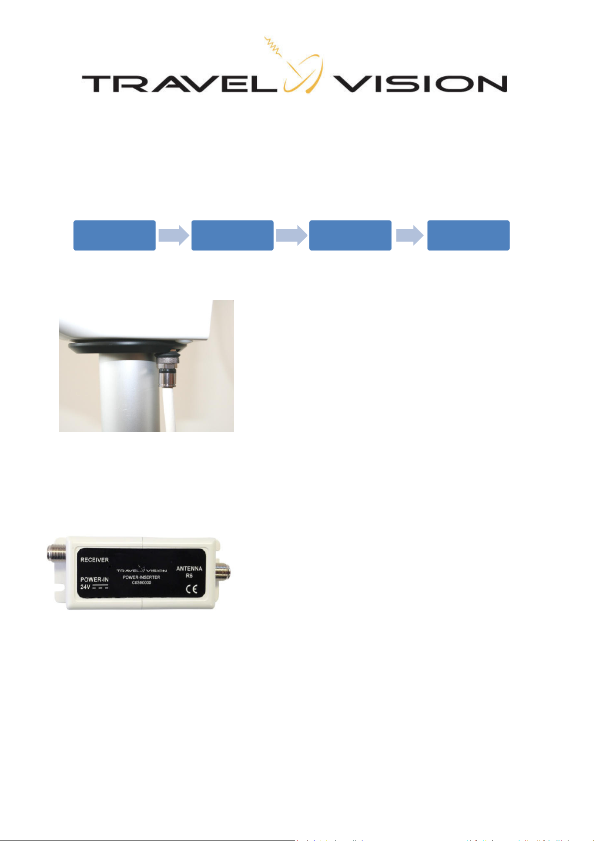
Firmly press the F-connector of the 15 mtrcoaxial cable over the
connector located on the bottom of the dish unit, so that the rubber is
indented, and hand-tighten it.
Coax
Press the F-connector on the other end of the 15 mtr coaxial cable
over the connector of the power inserter (indicated with “Antenna
R6”), so that the rubber is indented, and hand-tighten it.
Connect the short coaxial cable between the connector of the power
inserter (indicated with “Receiver”) and the “Antenna In” connector
of
your receiver, and hand -tighten both items.
Insert the power adapted jack plug (round plug) in the 24V port of
the power inserter (indicated with “Power-in 24V”) and insert the
power plug of the power adapter in a 230V wall outlet.
Receiver
Cable
Television
Page
8
the wiring as described in section 3.4,
to the antenna system by pressing it firmly into its socket.
On the display of the control module the following will be
within a few seconds, after which the system will present
this level, you can select the satellite of your choosing.
During its first usage, the system will preselect
ellite(s) and will show it
List of preprogrammed satellites from which you can choose:
Satellite
Eutelsat 7
SES 5
Thor
Eutelsat 5
Eutelsat 12
Telstar 12
Hispasat
and television. Then
The system will store and remember
3.5 Searching satellite
After connecting
connect the control module
switch on your satellite receiver
This last message will disappear
previously selected sat
Satellite Position
then shown:
TRAVEL VISION
Recreation
FIRMWARE V****
BOOTING
ASTRA1 19.2° ∞
TURN LNB TO 0
the Astra1 satellite.
on the display after startup.
Position
the satellite menu. At
Astra 1 19,2 E
Astra 3 23,5 E
Astra 2 28,2 E
Hotbird 13 E
Hellassat 2 39 E
Turksat 42 E
Eutelsat 9 9 E
7 E
5 E
1 W
5 W
12,5 W
15 W
30 W
page 9
10
You will see a blinking ∞ symbol on the right-hand side of the display that indicates the status of the GPS
location. As long as it is blinking, the system is searching for the GPS location. When the symbol is continuously
displayed, the system has determined its GPS location.
The time needed for the determination of the GPS location is approximately 2 minutes (see also next remark).
After determination of the correct GPS location, the system will be able to find the satellite more quickly. It also
provides for the opportunity to set the correct LNB and bracket position to ensure optimal reception.
The correct position of the LNB and bracket is shown on the display for each satellite, which may be different per
selected satellite. When the GPS location has not been found (yet), by default this position will be 0 for LNB and 1
for bracket.
Remark:
In case of a weak GPS signal, it might not be possible to determine the location. Before the system can be used
without GPS fix, the system will search for 4 minutes and after antenna movement 2 minutes for GPS signal. Only
after this procedure the system can be used for satellite searching.
However, finding the satellite will take longer and the optimal position of the LNB and bracket will not be provided.
If the GPS signal improves during satellite search, then the system will stop to display the right LNB and bracket
positions
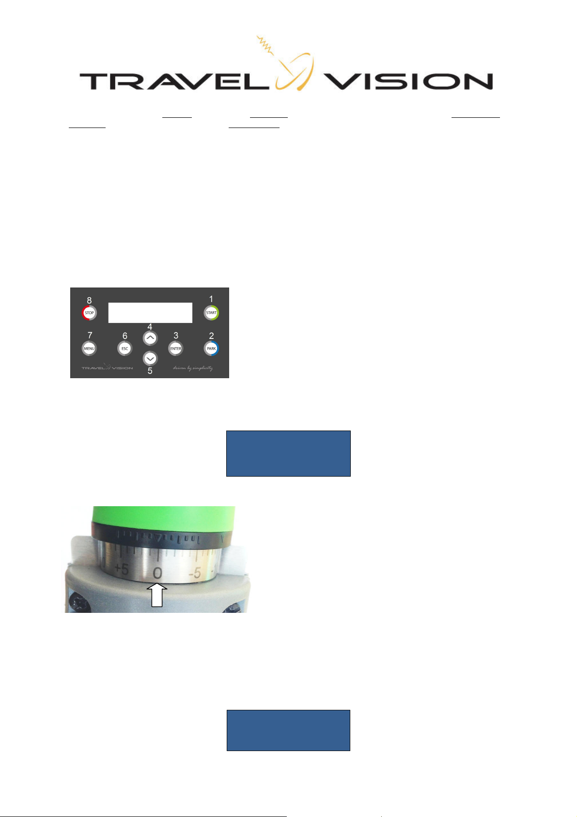
Select the desired satellite, read off the corresponding LNB position from the display, and bring the LNB into this
position by turning the LNB holder accordingly (see image below).
(Note: The mentioned LNB position is just an example)
Additionally the correct position of LNB will be indicated after GPS location has been determined.
After you have correctly positioned the LNB, press the Start button (1)
When the GPS location is not yet found, the GPS position will be located with countdown from 4 minutes.
.(see also 3.6 Special remarks on searching for satellite)
You can browse through the preprogrammed satellites step by step.
By means of the arrow buttons located on the control module (buttons
4 and 5), For each satellite, the correct LNB position is shown on the
display.
ASTRA1 19.2° ∞
TURN LNB TO 0
WAIT FOR GPS
.. min…sec
Page
Once the GPS position has been found,
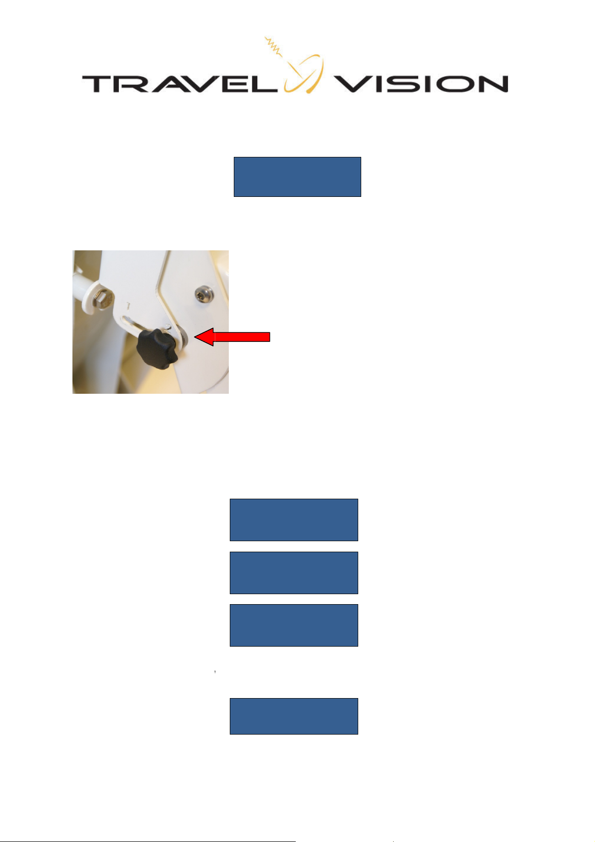
mentioned Dish position is just
Additionally the correct position of bracket will be indicated.
positioned the bracket, press the Start button (1)
on within 5 seconds and search
will be presented
After this startup phase, the system will automatically begin its search for the selected satellite. For example:
Once the Travel Vision R6 ® has found the satellite,
optimization of its alignment in small increments
and put the bracket in the
its vertical and horizontal reference points.
nal check followed by the
2 minutes. The display will
right position.
(Note: The
After you have
The system will start the calibrati
following messages
show the following message:
read off the corresponding bracket adjustment
DISH IN POS. 1
AND PRESS START
an example.)
Bracket in position 1 or 2
on the display:
CALIBRATING
PLEASE WAIT
CALIBRATING
ELEVATION
CALIBRATING
AZIMUTH
ASTRA 1 19.2 °
SEARCH SATELLITE
it proceeds with an inter
. This procedure will take about 1-
The
page 11

12
ASTRA 1 19.2 °
OPTIMIZE SIGNAL
After completion of the optimization phase the system is aimed exactly at the satellite. The following messages
are provided:
ASTRA 1 19.2 °
OPTIMAL SIGNAL
LNB IN POSITION **
MODULE CAN BE
REMOVED
The signal is now transmitted to the connected satellite receiver and you can watch television. Remove the
control module for safe storage.
3.6 Special remarks on searching for satellite
1. When no GPS location is found, the system displays after 4 minutes
Move the antenna to another place and press start to try again.
When after 2 minutes still no GPS location is found the system can be used without GPS location and
displays
When no GPS signal is found, the system will stop searching and displays Dish holder on 2, and press start for
second search. Finding the satellite will take longer (or satellite will be not found) because the optimal position for
the LNB and bracket is not provided
NO GPS FOUND
MOVE ANTENNA
AND PRESS START
WAITING FOR GPS
1:59 SEC.
NO GPS FOUND
DISH IN POS. 1
AND PRESS START
Page
earching for the satellite
the following message:
This indicates that the system has found the GPS location and that the position of the
has to be adjusted as shown on the display. If you do not adjust the LNB
a satellite signal.
to
When the system finds a satellite with the
system concludes it has not found the selected satellite
The system will automatically resume searching for the selected satellite.
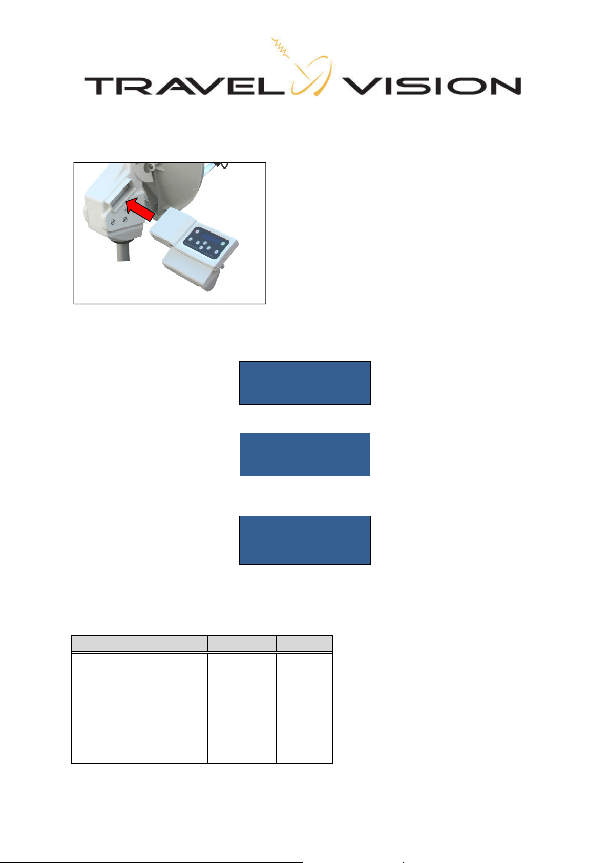
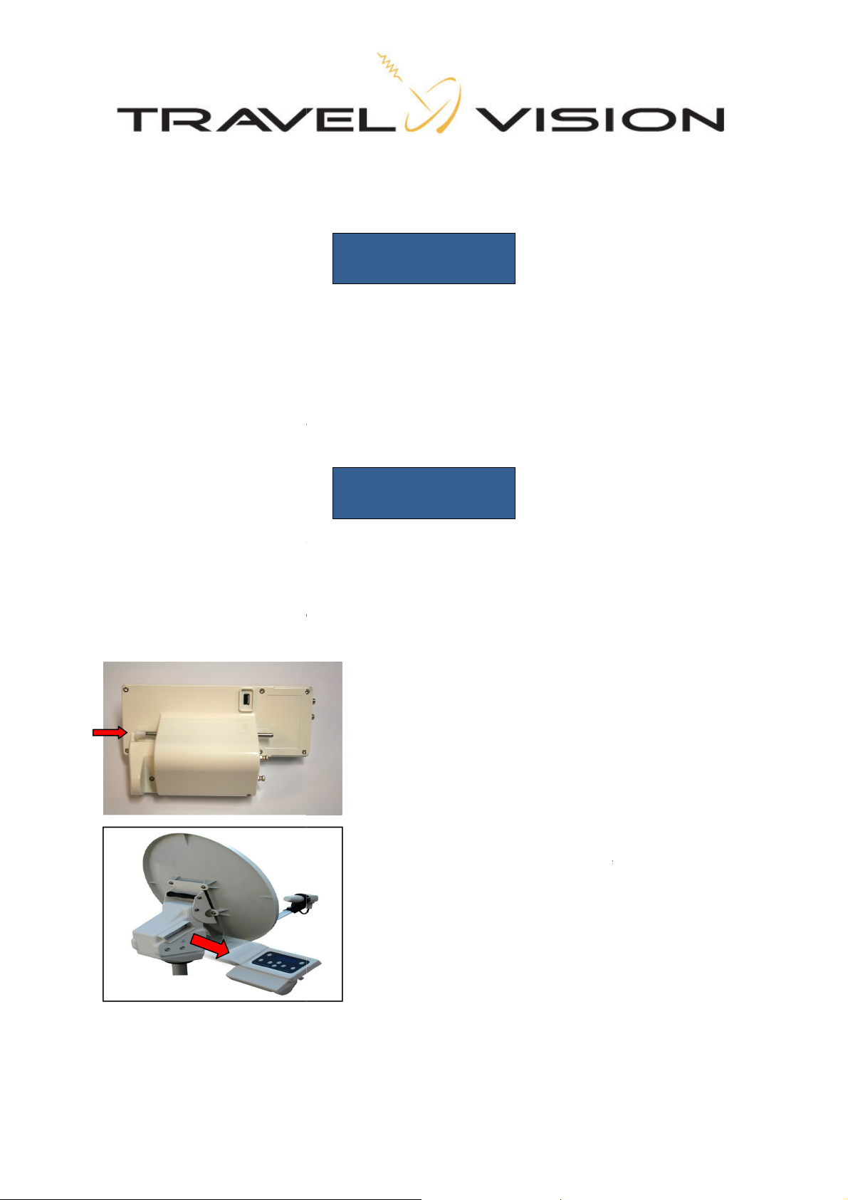
the control module
the bottom of the control module. Pr
proof so that you ca
the control module
suddenly stop searching and
and bracket
the system will resume
characteristics, the dish will stop rotating. But if the
, the following message
ess this release pin to remove
control module is unlocked after the release pen is pressed.
the control module by pulling it to the right. Do this
ensure that the current alignment of the dish is not altered.
n align the system when it is raining
to prevent theft and possible
2. uring s
show
system may not receive
Turn the LNB and bracket
searching.
3.
will be shown:
3.7 Removing
A release pin is located on
Remark:
The control module is splashthat you remove
water damage.
with no GPS location, the system could
ROTATE LNB --
AND PRESS START
the correct position and press the Start button (1)
correct
after the internal check
ASTRA 1 19.2 °
Incorrect sat.
The
Carefully remove
gently to
following each alignment of the system
LNB and bracket
position, the
the control module.
. We recommend
page 13

14
4.1 Menu
The menu provides for optional settings, including:
1) Language
2) Firmware update
1) Language
You can select English, German, French or Dutch as the user language.
Select the respective language with the arrow buttons (4 and 5) and press Enter (3) for confirmation.
2) Firmware update
The Travel Vision R6 ® searches for satellites based on various preprogrammed frequencies. These
frequencies have been carefully selected by Travel Vision BV, but they are subject to change. When
these frequencies change, Travel Vision BV will release new software so that the system can use the
new frequencies. This software is freely available for download at the website www.travel-vision.com
and at your local dealer. (be sure to download the Australian firmware update)
Download the software for your Travel Vision system from the website and store it on a USB flash drive.
Insert the USB flash drive in the USB port located on the bottom of the control module (see section 2.1).
The software transfer is only possible when the system is fully connected.
Select the firmware menu with the Enter button (3)
Press Enter and the display will show the current installed software version number. Press Enter again,
and the following message will be displayed:
Press Enter again
Press Enter again, and the system will be updated with the new software and will automatically reboot.
Remove the USB flash drive from the USB port. The system has now been updated with the new
software and is ready for use.
Press the enter button
Firmware update
TRAVELVISION
SETTINGS:
LANGUAGE
ENGLISH
SETTINGS:
FIRMWARE
Firmware :
REV 1.*.**
Are you sure?
UPDATE
*******
Recreation
Page

5.1 Park position
When storing the system, you should set it in the park position. In the park position the dish is rotated so
that the system is best suitable for storage.
Press on the blue park button (2) and you will see these messages:
Before storing the system, first disconnect the power supply before disconnecting the coaxial cable ans
disassembling the antenna with the tripod etc. (Optionally, a special bag is available in which you can store the
system).
6.1 Stop button
You can push the red Stop button(8) at any time and as a result, the system will stop all actions and will
start over by displaying the satellite choice menu
7.0 Error messages
7.1 No satellite found, check manual
CAUTION PARKING
IN ... SEC
SYSTEM
PARKED
MODULE CAN BE
REMOVED
SYSTEM STOPPED
When the satellite has not been found, you will receive the following message:
1. Check whether there are any obstructions. (See section 2.1)
2. Check if the latest Travel Vision R6 ® software version has been installed for any possibly changed
satellite frequencies. See www.travel-vision.com or consult your dealer.
3. You are possibly outside the broadcast area of the desired satellite.
SATELLITE
NOT FOUND
PLEASE CONSULT
MANUAL
7.2 Satellite found, but no picture
• Check the coaxial cable between the power inserter and your satellite receiver.
• Check the connection cables between your satellite receiver and your television.
• Switch the receiver and the television off and back on.
• Check the user manuals of your satellite receiver and television.
page 15

16
7.3 Satellite found, but not all channels
Check whether your subscription or smart cart is still valid.
7.4 Error No 24V connected:
The AC power adapter is probably not connected.
The PI inserter may be coonected the wrong way, Check all connectors and switch power off and back
on. Reinstall the control module. See also 8.2 troubleshooting
7.5 Error Voltage Low:
The voltage is too low for system to operate.
If you use the external satellite connector in your motor home or caravan: Connect the supplied 15 mtr
coaxial cable directly to the receiver and see if the system works. See also 8.2 troubleshooting
7.6 Error during software update:
Repeat the software update procedure
7.7 Error during software update:
Check if the software has been correctly stored on the USB flash drive.
7.8 Error during software update:
Insert the USB flash drive once more.
7.9 Error messages: calibration failed, error azimuth adjustment, error elevation adjustment
ERROR DURING
Check that there are no obstructions which hinder the rotation or alignment of the dish. Remove the
control module from the antenna unit and reinsert it again.
CALIBRATING
ERROR:
No 24V connected
ERROR:
Voltage low
E:ERROR DURING
UPGRADE
E:FIRMWARE NOT
FOUND
E:USB DISK NOT
FOUND
ERROR AZIMUTH
ADJUSTMENT
ERROR ELEVATION
ADJUSTMENT
Page

8.0 No LNB signal:
Check if the F-connector to the LNB is connected and tightened.
Check if the LNB cable is damaged.
Check the ac power adapter for 24 V
8.1 Error E: OXBAFF
Fault in electronics. The control module requires repair, contact your dealer.
8.2 Troubleshooting and frequently asked questions
Control module fails to illuminate, system fails to function. Possible causes and solutions:
NO LNB SIGNAL
E: OXBAFF
SEE MANUAL
• When using an external socket in a camper van or caravan: connect the coaxial cable supplied directly
to the receiver and check if the system is functioning. Next check your external socket.
• There is or there has been a short circuit.
Check the cables and connectors. The system must be reset: screw out the short coaxial cable from the
receiver on the power inserter, wait for 3 seconds and screw it on again. The power inserter has now
been reset and the system is ready for use.
• There is a problem with the receiver. Possible causes:
The receiver is not switched on.
If you have installed the control module in the system and you now tune the receiver to a random TV
channel, the 2nd green lamp on the power inserter will illuminate. At the same time the control module will
also illuminate and the system is ready for use.
LNB voltage is not switched on in the receiver menu.
Check the LNB voltage for the receiver, this is shown in the receiver's installation menu.
Display continues to indicate "Error, Low Voltage"
• Where an external socket is used, connect the supplied 15 metre coaxial cable directly to the power
inserter. See also the description of problems with an external socket.
• The correct adapter voltage is no longer present: check the 230 V mains supply voltage and the 24 V
adapter voltage.
• The 15m coaxial cable may be damaged and should be replaced.
The system displays: calibration error
• Probably the control unit is not properly installed. Remove power from the system and remove the
control module. Insert the module again and turn the power back on. If the error remains please contact
your supplier.
Should the system be level?
• The system may not exactly be level to find the satellite. However, the flatter the system is installed, the
faster the correct satellite is found. Also works in favour of the indicated LNB skew and bracket position.
page 17
 Loading...