

Travel Vision G6 Installation & Operation Manual
Travel Vision G6
Marine Satellite TV Antenna
Installation & Operation Manual

Marine Satellite TV Antenna
Installation & Operation Manual
Travel Vision G6
Copyright Notice:
The information contained in this document is proprietary to Travelvision BV. This document should
not be reproduced or distributed in any from without the consent of Travelvision BV. The
information in this document is subject to change without notice due to the functional upgrades of
the product. Copyright 2017 Travelvision. All rights reserved
2
Safety Notice
Do not operate the product in an explosive atmosphere.
Do not operate the equipment in the presence of flammable gases or fumes.
Operation of any electrical equipment in such an environment constitutes a definite
safety hazard. Keep away from live circuits
Operating personnel must not remove equipment covers. Component replacement
and internal adjustment must be made by qualified maintenance personnel. Do not replace
components with the power cable connected. Under certain conditions, dangerous voltages
may exist even with the power cable removed. To avoid injuries, always disconnect power
and discharge circuits before touching them.
Do not service or adjust alone
Do not attempt internal service or adjustments unless another person, capable of
rendering first aid resuscitation, is present
Observe marked areas
Avoid placing the product close to cigarettes, open flames or any source of heat
.
Observe marked areas
Under extreme heat conditions do not touch areas of the terminal or antenna that
are marked with this symbol, as it may result in injury
Distance to other equipment
Do not move the antenna closer to radars than the minimum safe distance
specified in the installation manual - it may cause damage to the antenna.
Minimum safe distance 1.2m.
Note:
Failure to comply with the rules above will void the warranty!!!
3

Table of Contents
Safety Notice
Table of Contents
Introduction to satellite TV antenna
Basic System of Travelvision
G6 Components 8
Antenna 8
ACU (Antenna Control Unit) 8
Accessories 9
3
4
6
7
Structure of G6
Before Installation the Antenna
Selecting location 11
Installation antenna
Auto skew angle control system
Installing of ACU
ACU Dimensions 20
Connecting the system cable
Single Receiver Connection 22
Dual Receiver Connection 23
Multi-Receiver Connection 24
Operation Instruction
Operation Instruction
Basic Mode 27
System startup 27
ACU Main Display and Key function 29
Data Communication Error 30
Change Target Satellite – Easy way 31
Monitoring Current Status – Searching status 32
Monitoring Current Status – Tracking status 33
Sleep Mode 34
Setup Mode 35
Begin Setup Mode 35
Set Target Satellite 36
Edit Satellite Information 37
Verification, Voltage, 22kTone Method 40
10
11
17
19
20
22
25
26
4

Set LNB Local Frequency – Universal 41
Set LNB Local Frequency – Single band 42
Set Use DiSEqC 43
DiSEqC Method 44
Set DiSEqC Satellite 45
Set Skew Control 47
Skew Control Method 48
Set Parameter – Antenna Operation Parameters 49
Antenna Operation Parameters 50
Set GPS 51
Execute Antenna Diagnosis 52
Antenna Operation Parameters 54
Set Antenna Go Position 55
Set Antenna Move Step 57
Display Power 59
Display Versions 60
Load Regional Satellite Information 62
Set Factory Default 64
Technical Specification 65
Warranty
66
5

Introduction to satellite TV antenna
Travelvision marine satellite TV antenna allows you to access “TV-Anywhere” with high quality
system where you are. The Travelvision antenna is designed to automatically track and identify
satellite signals using Digital Video Broadcasting.
The stylish Travelvision satellite TV antenna use automatic ABSS (Active Beam Scanning
System) technology to find the satellite signal quickly in harsh weather conditions and the
new Antenna Control Unit makes easy to access satellite information.
GPS equipped supports an automatic satellite acquisition
Travelvision G6 Marine Satellite TV Antenna:
•
High-gain antenna with stylish radome
•
Powerful tracking system using a GYRO sensor built-in
•
DVB Technologies
•
Easy change target satellite
•
Change the target satellite by DiSEqC signal
•
Skew angle varies by location of antenna
•
Built-in GPS
•
Built-in world satellite library
6
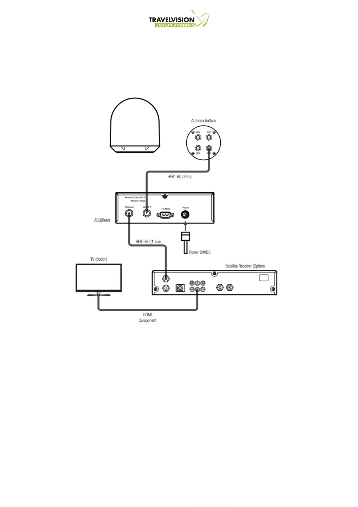
Basic System of Travelvision
To start the operation of satellite TV antenna, connections should be completed with Antenna
Control Unit (ACU), satellite receiver and a television like below.
Composite (RCA)
Note:
TV and IRD is not supplied by TRAVELVISION and to be provided by a Local Service
Provider.
7

G6 Components
Travelvision G6 satellite TV antenna includes the following components.
Antenna
The antenna unit is comprised of the antenna mechanism, a main reflector, sub reflector, horn
and LNB for the supreme signal
ACU (Antenna Control Unit)
•
Monitors & controls the status of antenna
•
Provides power to antenna unit
•
Changes target satellite by DiSEqC signal
•
Perform self-diagnosis of antenna system
•
Set up antenna system using PC program
Note:
ACU mounting bracket (Ceiling or Desk fixed) are supplied together.
8
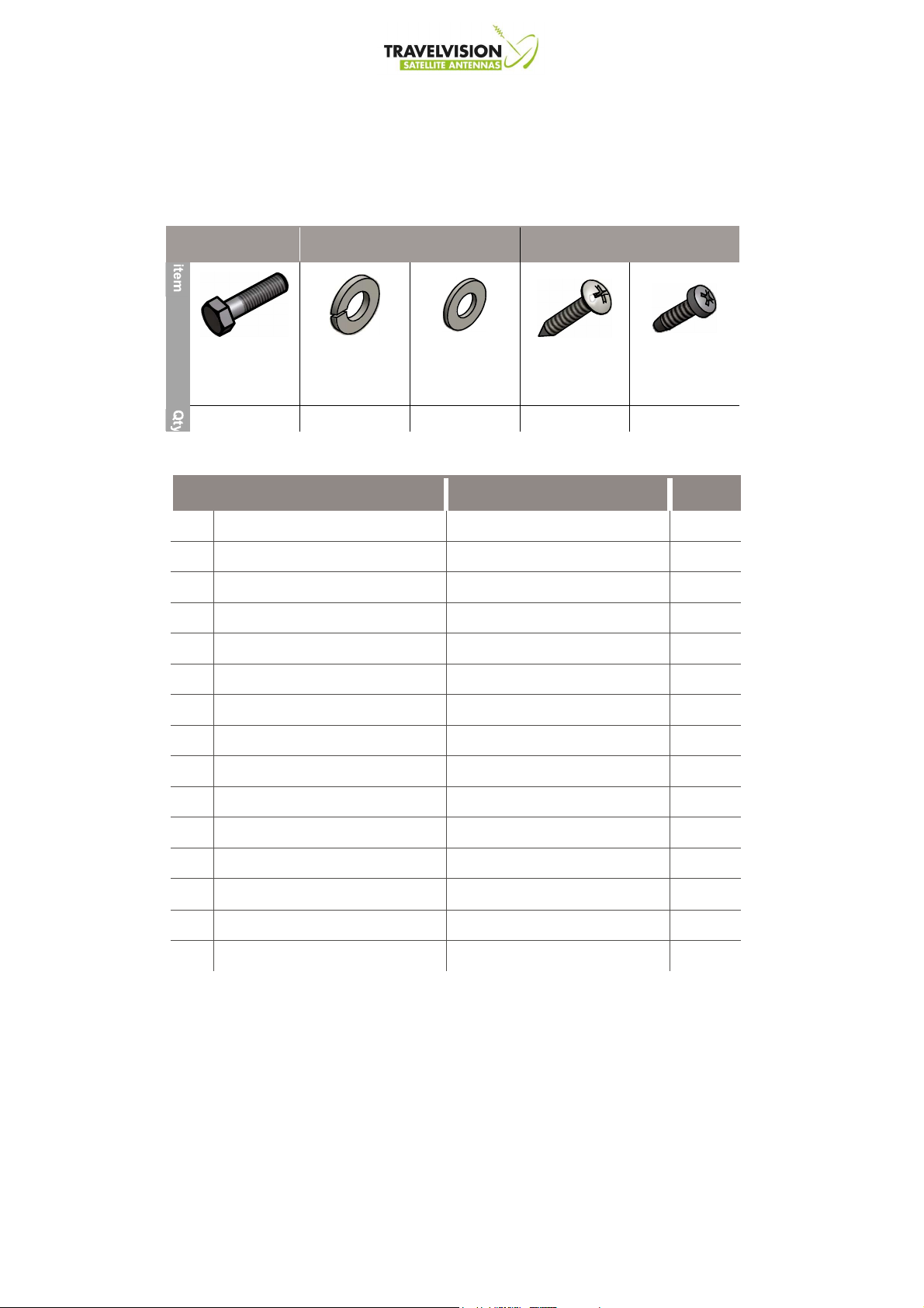
Accessories
• Antenna installation Bolt Kit
Antenna
ACU
M8
5
Flat Washer
Hex Bolt
M8x40L
Spring Washer
5
M8
5
Self-Tapping Screw
M4x16L
Self-Tapping Screw
5
• Other Component
No. Component Specifications Qty
1. Power Supply Unit
2. AC Power Cable
Only SMPS Type
Only SMPS Type
3. RF Cable (Antenna to ACU) 20M (HFBT-5C) 1
4. RF Cable (ACU to Receiver) 1.5M (HFBT-5C) 1
5. DC Power Cable
Only DCDC Type
6. DC Power Connector
7. ACU Table Mounting Bracket - 2
8. PC Program CD - 1
9. User Manual - 1
AC100~220 VAC 50~60Hz 1
1.5M (E type) 1
10M 1
Only DCDC Type
5ESDV-3P 1
M3x08L
5
10. Quick Installation Guide - 1
11. Hex Bolt
12. Spring Washer
13. Flat Washer
for antenna installation
for antenna installation
for antenna installation
14. Self-Tapping Screw
15. Self-Tapping Screw
M8x40L 5
M8 5
M8 5
M4x16L 5
for ACU
M3x08L 5
for ACU
List of the Supplied Parts
9

Structure of G6
•
Reflector : Capture radio waves.
•
Sub-reflector : Transmit radio waves to Horn and scanning automatically wave value to track
target satellite.
•
LNB (Low Noise Block) : Convert the signals from radio waves to electrical signals.
•
Step Motor : Control the angle of Elevation and Azimuth.
•
ODU (Out Door Unit) : Built-in the control board of antenna.
•
GPS (Global Positioning System) : Support to track quickly target satellite information.
•
Auto Skew System : Automatically adjusts the antenna's skew to calculate of target satellite
and GPS location.
10
I
f the platform is not flat, it will increase the antenna searching time.
Before Installation the Antenna
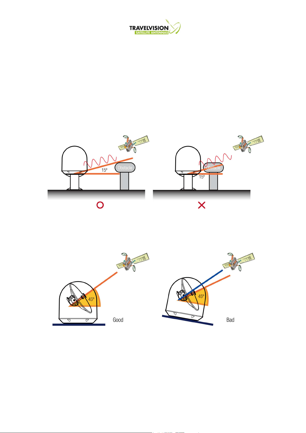
Selecting location
• Minimize blockage
Any obstacles located above 15 degree
elevation can prevent the antenna from
tracking satellite signal
• Flat platform and strong enough to support the weight of the antenna.
Elevation default setting: 45°
Searching time : <30sec
11
Elevation default setting: 45°-10°=35°
Searching time: 2~5 minutes
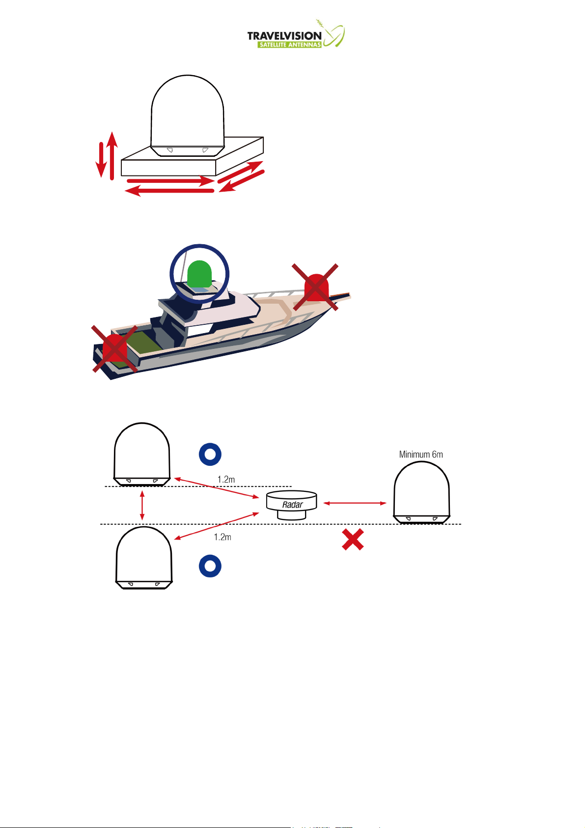
• Flat platform and strong enough to support the weight of the antenna.
- I
t should be placed away from excessive
vibration to avoid unnecessary motion
which can affect reception
• Near to the center of boat as possible
• Radar interference
For a good performance, the antenna unit must be
placed as close as possible in the centerline with
free space around. It should be away from the
edge of the boat to avoid unnecessary motion
Antenna should be clear of any radars because
their energy levels may overload the antenna
front-end circuits
12
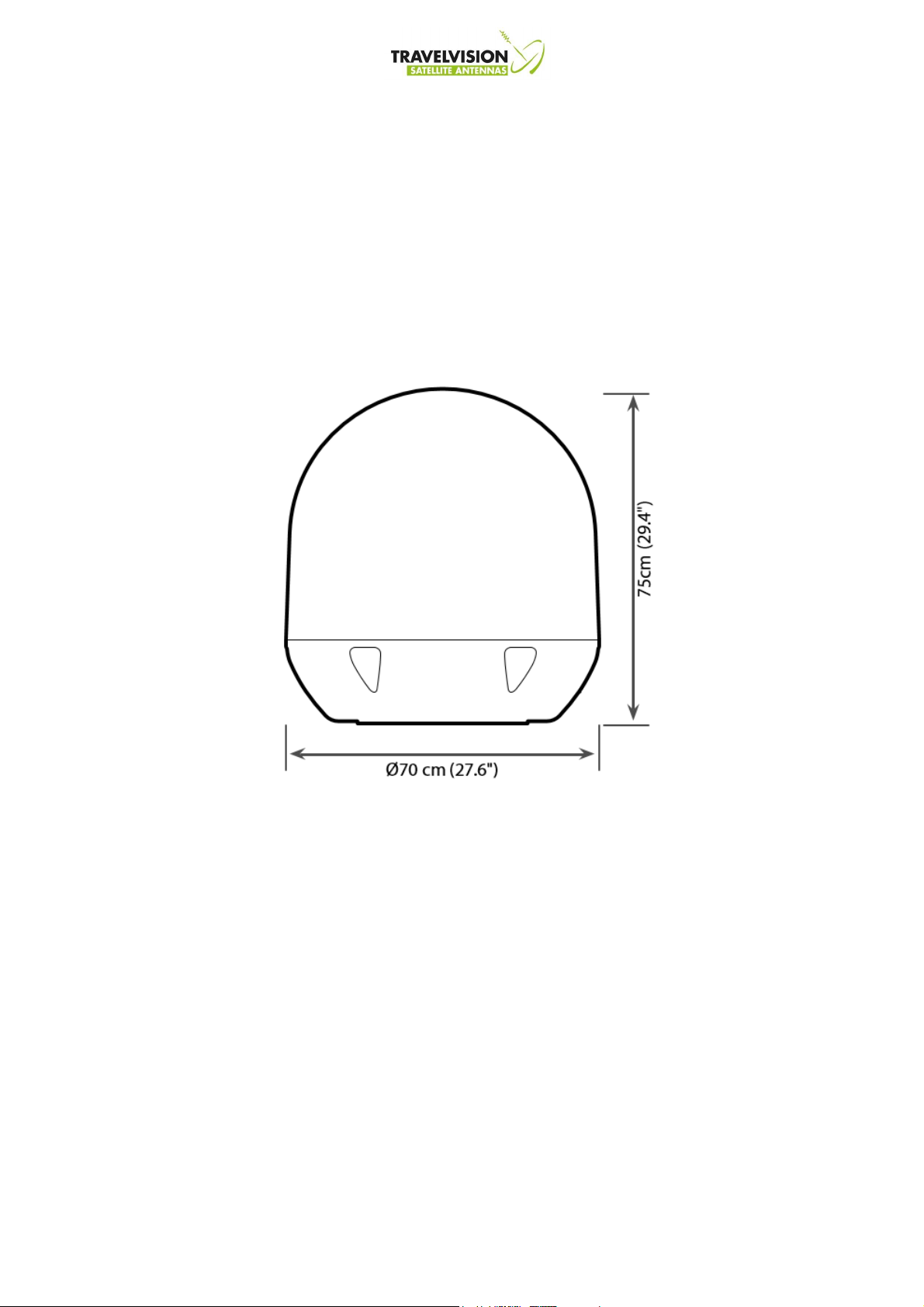
• Confirmation of Size Prior to Installation
The space must be sufficient for installing the antenna unit considering the height and
diameter of the antenna. The height and the diameter of the bottom surface of the antenna
are as shown in the following drawing. If possible, install the antenna on strong enough
steel mast.
Note: Before installing the antenna, open the radome and remove the shipping constraints
from the antenna interior.
13
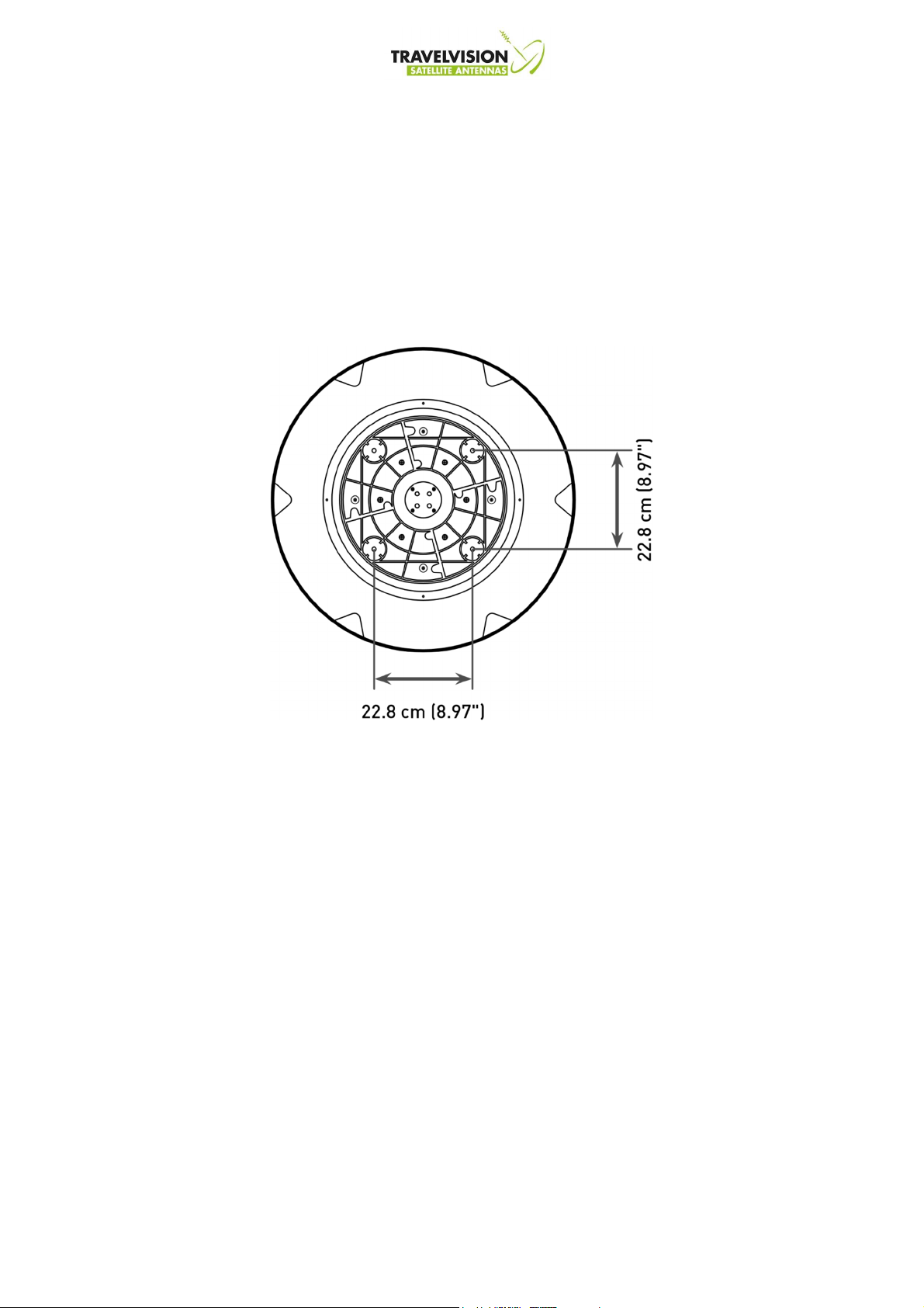
• Mark of the Antenna Mounting Position
Referring to the mounting template, mark where antenna will be mounted on board (it must
be a flat surface) or on a separate power
Note: Mounting Bolts enclosed with the antenna should be used for the antenna installation.
Use of different length of mounting bolts is prohibited.
14

• Power and cable required for installation.
Check power supply available Travelvision G6 has been designed to work with 2 type of power
supply AC or DC
1. AC Type
2. DC Type
RF Cable
Before installing the system, consider the following points.
- All cables need to be well clamped and protected from physical damage and exposure to
heat and humidity - Cables with severe bends are not allowed.
- Where a cable passes through an exposed bulk head or deck head, a watertight grommet
or swan neck tube should be used.
- Connect RF cable between RF1 on antenna and ANT.RF1 on ACU
- RF cable is supplied at length of 20m
- Can be extended up to 50m
- Use AC/DC adopter and connect to AC power supply 110~240VAC
- Antenna has been designed to work on power supply 24VDC
- Connect to DC supply 9 ~ 30VDC
- Antenna has been designed to work on power supply 24VDC
15
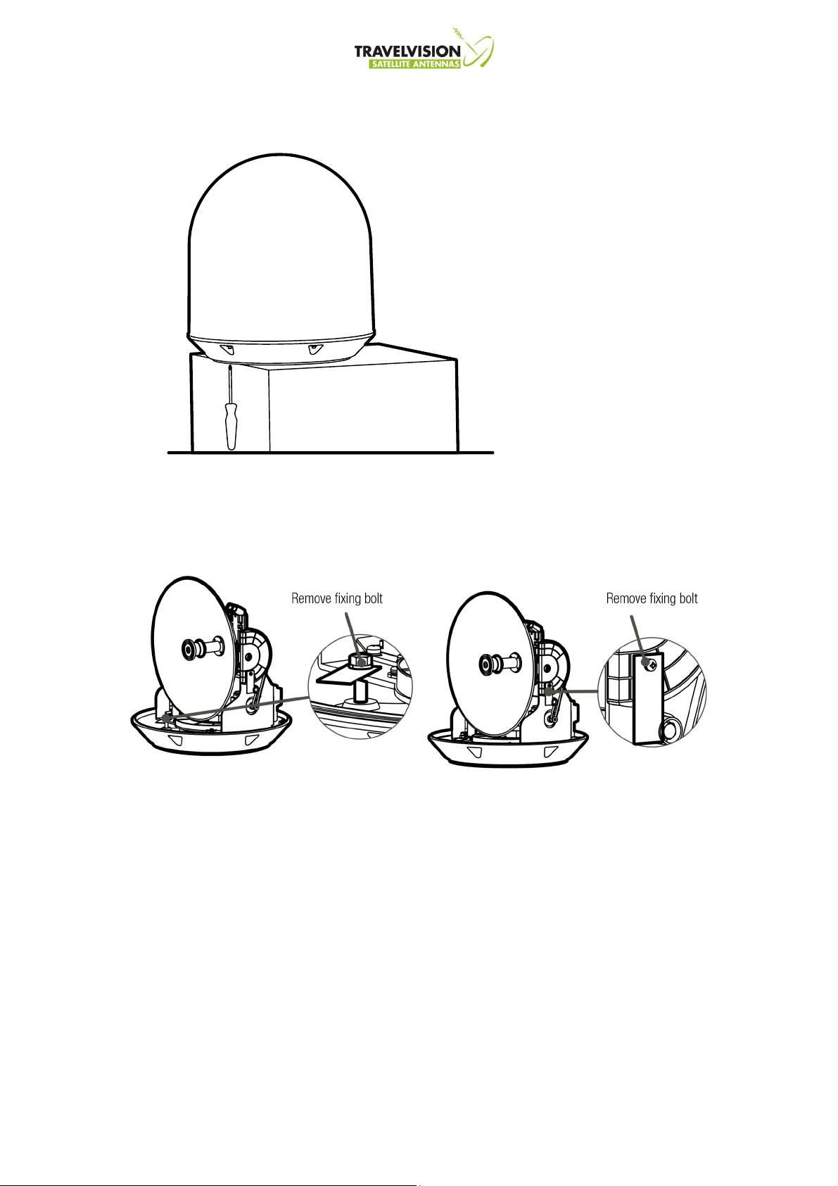
• Remove the fixing bolts before installation
Before installing the antenna unit, you must remove the fix bolts of the antenna inside
Remove the 6 bolts securing the radome from
antenna unit base and open the radome
.
• Remove 2 bolts tagged to secure the antenna frame during the shipment.
Inspect the antenna unit for shipping damage.
Please try to operate the dish of azimuth and elevation at the end of the end of the limit switch,
after removing bolts. Cover the radome with bolts tightly after checking all system
16
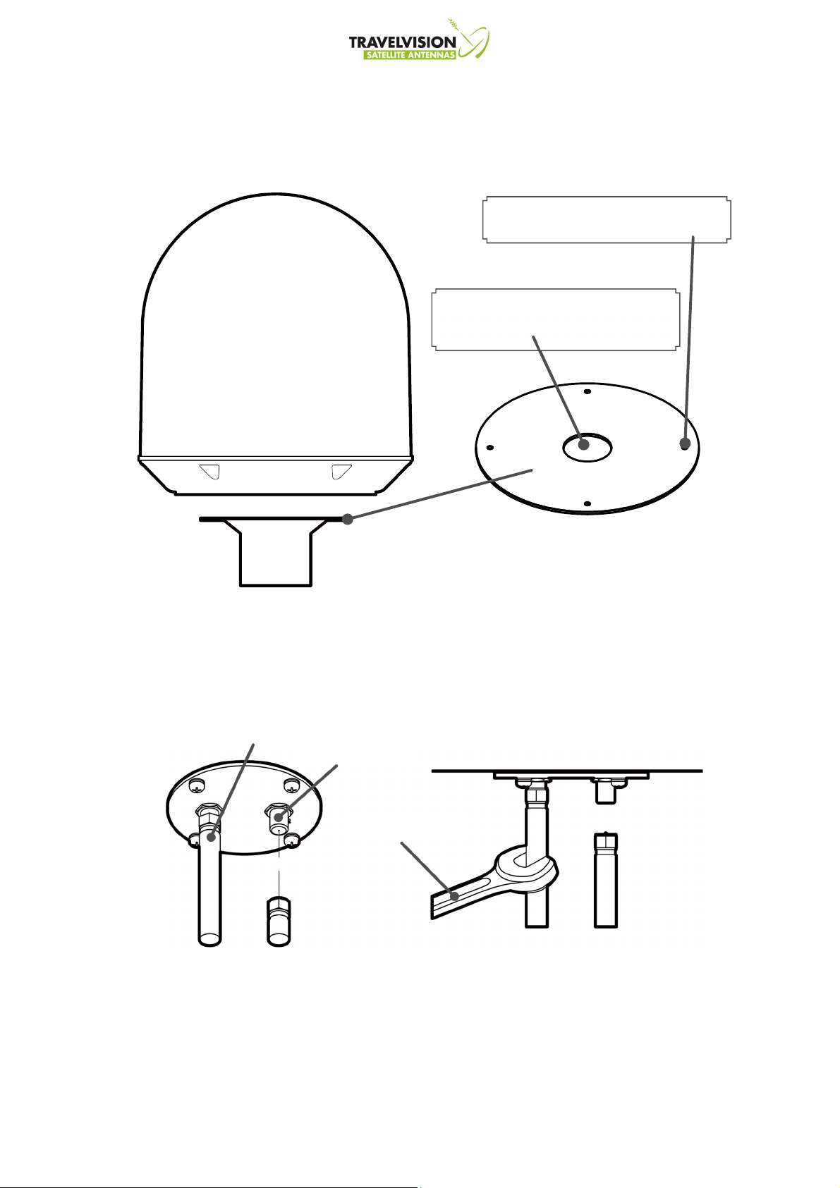
Make a circular hole of 80mm diameter
RF connector
11mm spanner
RF cable
Installation antenna
• Antenna fixing sheet
Make 4 bolt holes of 10mm diameter,
one at each corner of a circular.
at the center which the cable will run.
Mounting sheet
Mast
• Connection of the Cable
Connect the RF cable to the RF connector under the base plate through the access
hole using an 11mm spanner. Be careful not to over tighten, as you may damage the
connector.
RF cable
17
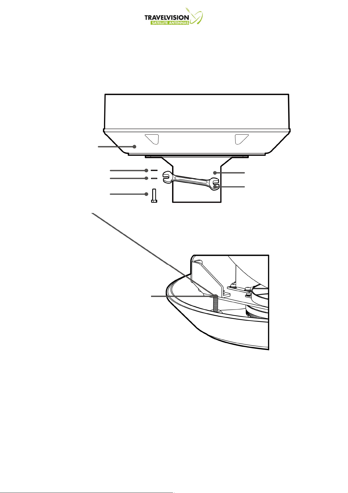
Antenna
Mast
13mm spanner
• Mounting the Antenna
Attach the antenna by using the hex head bolts (M8X35L), M8 spring washers, and
M8 flat washers supplied.
M8 Flat Washer
M8 Spring Washer
M8 Hex. Bolt
Length: 40mm
When using a longer bolt subject
to interference with the rotation.
18

Auto skew angle control system
•
G6 has an embedded auto skew angle control system.
Therefore, manual adjustment of LNB skew angle is not required. The LNB skew angle
is continuously adjusted automatically thought of the calculation of current GPS location
and target satellite. The Skew angle of LNB is shown from the ACU and PC Program.
19
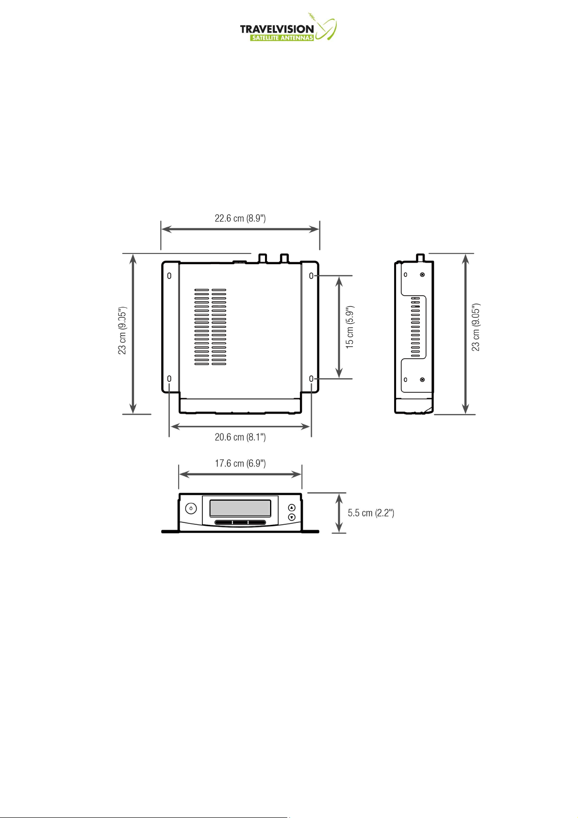
Installing of ACU
ACU Dimensions
• Selecting ACU Installation Site
The ACU should be installed below deck, in a location that is:
•
Dry, cool, and ventilated.
•
Easy access from your main TV viewing area.
20
 Loading...