

Travel Trac RealAxiom User Manual
interactive
indoor
training
system
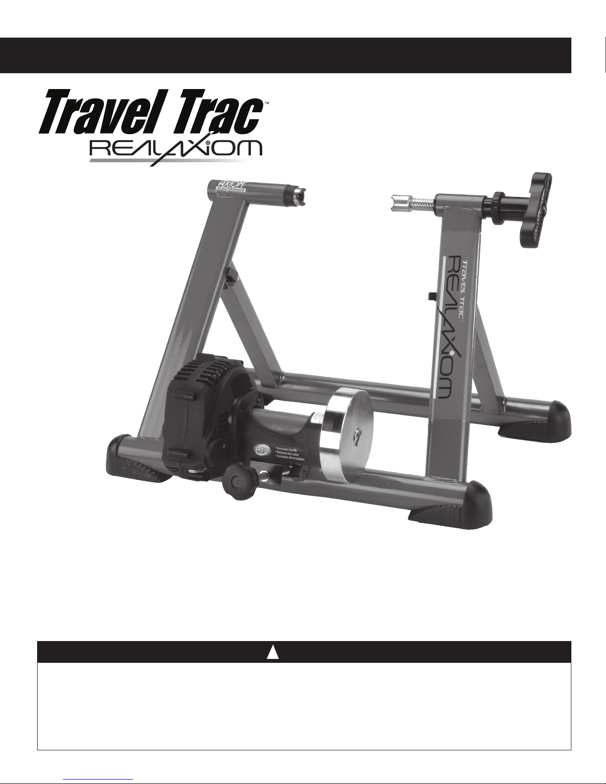
Thank you for your purchase of the Travel Trac™ RealAxiom interactive indoor training system.
Combine your bicycle and personal computer with the RealAxiom trainer and software for the ultimate interactive training experience. The RealAxiom allows you to ride interactive courses with and
without video synchronization while tracking and recording speed, distance, ride time, cadence,
power, and heart rate. Your indoor training has never been as fun or effective as it will be with the
Travel Trac™ RealAxiom.
• Read and follow all instructions.
• Before beginning each workout, be sure bicycle is securely attached to the trainer.
• During use, resistance unit may become hot enough to cause burns. Do not touch resistance unit during use or for some
time after use until it has had sufficient time to cool.
• Keep children and pets away from the trainer during use.
• Before you start any exercise program you should consult a physician.
• This trainer is intended for single-rider bicycles only.
!
! CAUTION
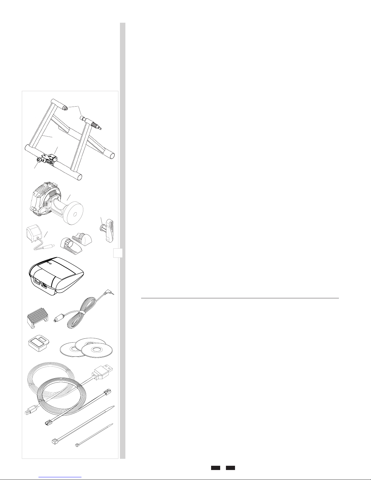
Table of Contents
I. Parts List and System Overview ................................................................2
II. System Requirements ................................................................................. 3
III. Assembly Instructions .................................................................................3
A. Trainer Assembly ............................................................................ 3
B. Bicycle Installation ......................................................................... 3
C. SofTrac Drive Roller ........................................................................ 4
D. Handlebar Console Installation .....................................................4
E. Cadence Kit Installation .................................................................4
F. Cable Connections ..........................................................................5
G. Using the Travel Trac RealAxiom without a PC ........................... 5
IV. Hardware and Software Installation ..........................................................5
V. Program Overview .......................................................................................6
H
A
C
D
B
G
P
E
F
VI. Before You Begin ..........................................................................................6
A. Using the Keyboard, Mouse and Handlebar Console ................. 6
B. Create Rider Profile ......................................................................... 7
C. Edit or Delete an Existing Profile ..................................................7
D. Using a Heart Rate Transmitter Strap .......................................... 7
E. Pre-Ride Checklist ...........................................................................8
VII. Riding a RealAxiom Interactive Video Course ..........................................8
A. Choose a Course ............................................................................. 8
B. Create a Sub-course ....................................................................... 8
C. Select and Adjust Competitor .......................................................9
D. Starting the Course ........................................................................9
E. During the Ride ............................................................................... 9
F. Finish the Course ........................................................................... 10
VIII. Riding an Axiom (non-video) Course ....................................................... 10
A. Choose a Course ........................................................................... 10
B. Adjust Competitor ........................................................................10
C. Starting the Course ...................................................................... 11
D. During the Ride ............................................................................. 11
E. Finish the Course .......................................................................... 11
IX. Viewing History Screens ...........................................................................12
X. Customizing Your Workout ....................................................................... 12
A. Heart Rate Target Zone Settings................................................. 12
B. Adjusting the Competitor ............................................................12
C. Creating Your Own Course .......................................................... 12
XI. Troubleshooting ............................................................................................13
1
I
I. Parts List
Part Part Code Quantity
K
J
M
L
N
O
Travel Trac™ RealAxiom Trainer Base ...............A ........................................ 1
Resistance Unit ....................................................B ........................................ 1
Resistance Unit Mounting Plate .........................C ........................................1
Knob Bolt .............................................................D ........................................1
Rubber Feet ..........................................................E ........................................ 4
Handle ..................................................................F ........................................ 1
Locking Ring ....................................................... G ........................................ 1
Axle Support Cups ..............................................H ........................................2
Handlebar Console .............................................. I ......................................... 1
Rubber Shims ...................................................... J ........................................ 2
Cadence Sensor and Cable .................................K ........................................ 1
Cadence Magnet .................................................. L ........................................1
Software and DVD Courses ............................... M........................................ 3
Console-PC Cable ............................................... N ........................................ 1
Console-Resistance Unit Cable ......................... O ........................................ 1
Resistance Unit Power Cord ............................... P ........................................ 1
Large Zip-tie ........................................................ Q ........................................ 1
Small Zip-ties .......................................................R ........................................ 3
Q
R
2

System Overview
• Components included with your Travel Trac™ RealAxiom shown in black.
• Owner supplied components shown in grey.
II. System Requirements
• PC: Pentium 3 or better
• Operating system: Windows 2000, Windows NT or Windows XP
• Hard disk: 10GB of free disc space / 7200 RPM
• RAM: 256MB
• Monitor: 800 X 600
• Port: USB
• DVD Drive
2
Monitor
PC
N
I
K
A
L
O
B
P
III. Assembly
Note: All references to Left and Right are from the rider’s perspective.
A. Trainer Assembly
1. Remove the trainer base, resistance unit and all parts from the box. If you
believe parts are missing, please contact our Technical Support department
for assistance at 1-800-553-8324.
2. Attach the rubber feet (E) to the trainer base (A) by pressing them into the
ends of the trainer base frame tubes. See Figure 3.
3. Attach the handle (F) to the end of the axle support bolt that protrudes from
the trainer base. Align the “D” shaped end of the bolt with the corresponding
recess inside the handle, and tap the handle lightly into place. See Figure 3.
4. Attach the resistance unit (B) to the mounting plate (C) using 2 M5 bolts and
washers as shown in Figure 4.
B. Bicycle Installation
! WARNING
Read and follow all instructions concerning installation of the bicycle on the trainer.
Failure to securely attach the bicycle to the trainer could result in the bicycle falling,
causing injury to the rider or bystanders.
1. Place the trainer base on a flat, stable surface near your computer so that
you’ll have a clear view of the monitor when seated on the bike.
2. Note: Replace the bicycle’s rear wheel quick release (QR) skewer with the
one provided with the trainer. See bicycle owner’s manual for instructions
on how to properly adjust the QR skewer. Make sure the QR skewer is tight
and not damaged or bent.
3. Loosen the locking ring (G) by sliding it all the way to the right until it contacts
the handle (F). See Figure 5. Spin the handle counterclockwise to fully loosen
the right side axle support cup (H).
4. Loosen the knob bolt (D) by turning it counterclockwise so that the resistance
unit is as close to the floor as possible (to provide clearance for the rear wheel).
5. Lift the bicycle into position, so that the rear QR skewer is aligned with the
right and left axle support cups (H). See Figure 6.
6. Fit the QR skewer lever on the left side of the wheel into the left axle support cup. Rotate the support cup as necessary, until the notch in the cup is
aligned with the QR skewer lever.
7. Tighten the right side axle support cup against the QR skewer nut on the right
side of the wheel by spinning the handle clockwise until it contacts the QR
skewer nut. Once contact is made, tighten the handle an additional 1/4 to
1
/2 rotation, until the QR skewer is firmly clamped between both axle support
cups.
8. Tighten the locking ring (G) by sliding it all the way to the left (toward the
F
3
E
B
4
5
6
D
H
UNLOCKED
LOCKED
C
G
F
H
H
F
3
bike). See Figure 5.
9. Check that the bicycle is securely installed in the trainer by pushing or pulling on the bicycle’s top tube or seat.
10. If the bicycle is not secure, check to see that the QR skewer lever and nut
are properly positioned in the axle support cups, and that the right side axle
support cup is securely tightened.
11. It is important to maintain the correct pressure between the tire and the drive
roller. Tighten the Knob Bolt (D) until the drive roller touches the tire. Then
turn the Knob Bolt an additional three complete rotations. If the tire slips
during use, tighten the bolt by additional
1
⁄2 turns to eliminate the slippage.
! WARNING
Failure to securely attach the bicycle to the trainer could result in serious injury.
C. SofTrac Polyurethane Drive Roller
The unique SofTrac drive roller on the RealAxiom is made of durable polyure-
thane, which significantly reduces tire noise and tire wear while increasing traction between the tire and roller (less tire slippage). There are a few important
points to keep in mind about the SofTrac roller.
1. To avoid damaging the roller, DO NOT apply the rear brake while using the
trainer. Locking the rear wheel at high speed can seriously damage the polyurethane roller.
2. Allowing the tire to slip against the roller will also accelerate roller wear.
Maintain sufficient pressure between the tire and the drive roller to prevent
slipping. During installation, tighten the Knob Bolt (D) until the drive roller
touches the tire. Then turn the Knob Bolt an additional three complete rotations. If the tire slips during use, tighten the bolt by additional
7
eliminate slippage.
3. Pedaling with a smoother stroke and applying power more evenly when
accelerating will also help prevent the tire from slipping.
4. Use a smooth tread tire at least 23mm in width.
5. Maintain the recommended maximum inflation pressure for your tire.
6. Over time the SofTrac roller may show some slight signs of wear. This is
1
⁄2 turns to
CAUTION
To avoid damaging roller, DO NOT apply rear brake while roller is spinning.
L
Q
L
Q
R
K
R
8
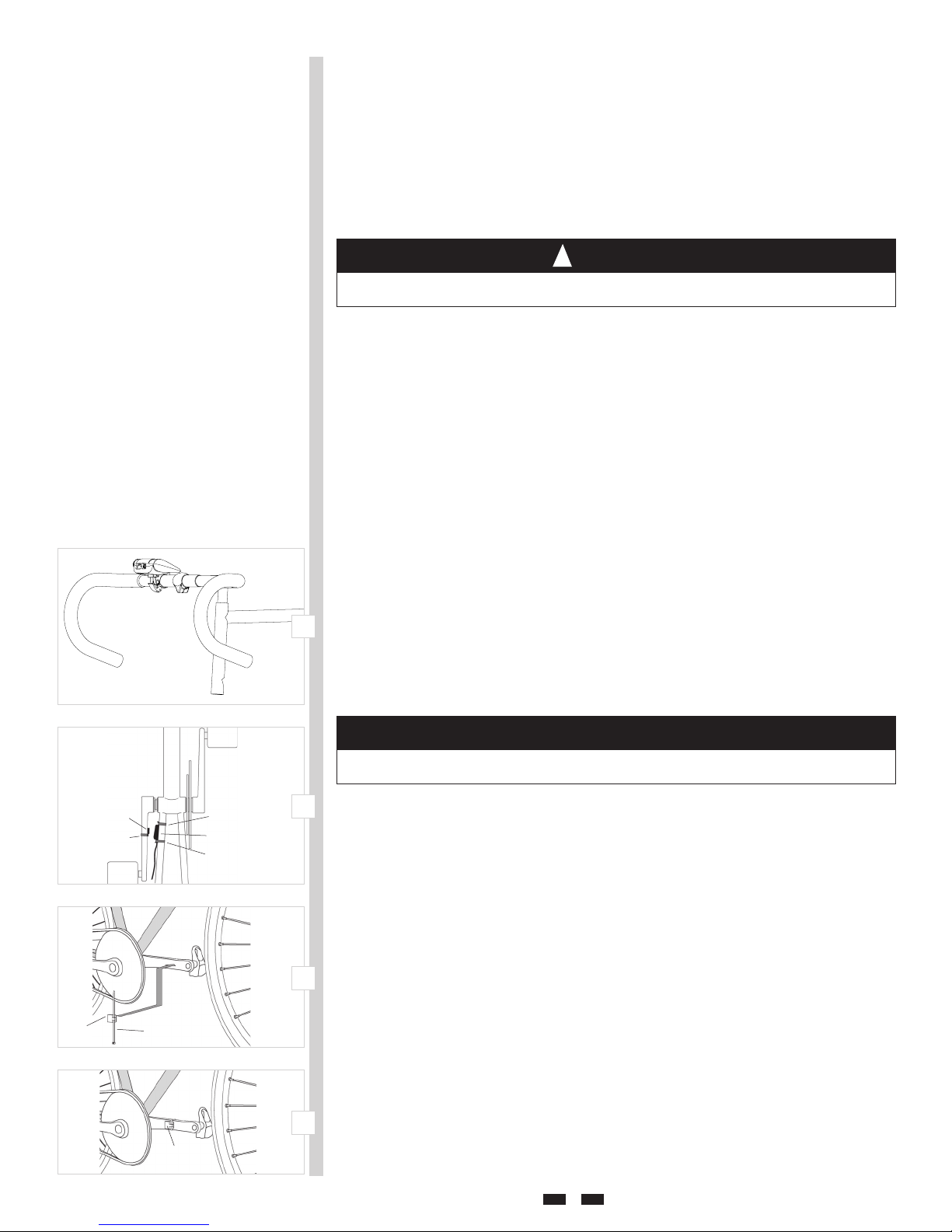
D. Handlebar Console Installation
9
E. Cadence Kit Installation
The cadence kit consists of a magnet (attached to the crank arm) and a sensor
10
L
normal, and does not affect the performance of the roller.
1. Attach the console to the handlebar as shown in Figure 7. Open the quick
release bracket and install on the handlebar, preferably close to the stem.
For use on larger diameter handlebars, it may be necessary to remove the
two rubber shims (J) from the bracket.
2. Spin the quick release lever to adjust bracket clamping tension, and then flip
the quick release lever upward to secure the bracket in place.
3. If the bracket clamping tension is too loose or too tight, open the quick
release lever, adjust clamping tension, close the lever and re-check for
secure attachment.
(attached to the left chainstay), which counts the number of pedal revolutions
per minute.
1. Loosely attach the sensor (K) to the outside of the left (non-drive side) chain
stay using two zip-ties (R). See Figure 8.
4

2. Loosely attach the magnet (L) to the inside of the left crank arm using one
zip-tie (Q). See Figure 9 and 10.
3. Position the sensor and magnet so that the space between them is no more
than 2-3mm. Proper spacing is often achieved by sliding the magnet and
sensor toward the rear of the bike. See Figure 11.
4. Once the magnet and sensor are positioned properly, tighten the zip-ties
securely. Secure the sensor cable to the chain stay using additional zip-ties
as necessary, and trim the loose ends from all zip-ties to prevent contact
with the spokes or drivetrain components.
11
F. Cable Connections
Handlebar Console to PC
Connect one end of the USB cable (N) to the handlebar console and the
other end to an available USB port on your PC. See Figure12a.
Console to Resistance Unit
1. The console to resistance unit cable (O) has a phone jack type plug at both
ends.
2. Plug one end of the cable into the appropriate outlet at the back of the console. See Figure 12a.
3. Plug the other end of the cable into the appropriate outlet at the back of the
resistance unit (B). See Figure 12b.
Cadence Sensor to Resistance Unit
Plug the cadence sensor cable (K) into the appropriate outlet at the back of
the resistance unit.
Resistance Unit to Power Supply
Only after all other connections are complete, connect the resistance unit
power cord (P) to the resistance unit and then to a standard electrical wall
outlet (120V AC). If all cables are connected correctly, the green LED on the
console should be lit.
G. Using the Travel Trac™ RealAxiom without a PC
The RealAxiom can be used as a stand-alone trainer, independent of the
PC. When the handlebar console is not connected to the PC, the green LED
on the console will flash green. Use the "+" and "-" buttons on the console
to increase or decrease the resistance level. There are 8 levels to choose
from. The red LED on the console will flash each time the resistance level is
adjusted. After 20 seconds of inactivity, the resistance level will automatically return to the lowest level.
12a
12b
I
O
N
P
K
O
IV. Hardware and Software Installation
Your Travel Trac™ RealAxiom includes software compatible with Windows® 2000, NT
and XP. The software also includes the USB driver required for the handlebar console.
A. Software Installation
1. Insert the RealAxiom CD in the CD-ROM drive. The installation should begin
automatically. If the installation does not start automatically, click on the CDROM drive to explore the contents, and double click the "RealAxiomInstall"
icon.
2. Follow the on-screen installation instructions. When the installation is complete, remove the CD.
3. During the software installation the USB driver for the handlebar console
will also be installed automatically, and a RealAxiom desktop shortcut will
be created.
4. Insert the Verona Championship Course DVD or Limoges Course DVD.
5. The DVD course installation should begin automatically. During installation, be sure to select the desired units of measure (Metric or English). If the
installation does not start automatically, click on the DVD drive to explore
the contents and double click the Setup icon.
6. The DVD course installation may require several minutes.
5
 Loading...