

Travaini Pumps USA TRS 32-20, TRH 32-4, TRS 32-50, TRH 32-20, TRH 32-45 Operating & Maintenance Manual
...
Continuing research of TRAVAINI PUMPS USA results in product improvements; therefore any specifications may be subject to change without notice.
PRINTED IN USA
F:/MVUOTGB4
DATE 4/02
Operating &
Maintenance
Manual
for
Liquid Ring
Vacuum Pumps,
Compressors
& Systems
TRH-TRS-TRM-TRV-SA
Water Sealed & Oil Sealed (DynaSeal
TM
)
Systems
Liquid Ring & Rotary Vane Vacuum Pumps and Systems
Web Site: www.travaini.com
200 NEWSOME DRIVE
YORKTOWN, VA 23692
Telephone: 757.988.3930
Toll Free: 800.535.4243
Fax: 757.988.3975
Liquid Ring & Rotary Vane Vacuum Pumps and Systems
OUR PRODUCTS
LIQUID RING
VACUUM PUMPS
LIQUID RING COMPRESSORS
ROTARY VANE VACUUM PUMPS
ROTARY VANE VACUUM SYSTEMS
MEDICAL SYSTEMS (NFPA99)
PACKAGE VACUUM SYSTEMS
WITH PARTIAL OR TOTAL
SERVICE RECIRCULATION
CUSTOM ENGINEERED
VACUUM SOLUTIONS
This manual applies to TRAVAINI PUMPS USA
liquid ring pumps single stage series TRM, TRS,
TRV, double stage series TRH, compressors
series SA and systems series water sealed and
oil sealed (DynaSeal
TM
) Systems, which utilize
above pump series. (Please see section 18 or 19
for details pertaining to systems).
NOTE:
Unless otherwise specified, the term
pump used throughout this manual means also
pump/motor assembly or system type water
sealed or oil sealed (DynaSeal
TM
).
MANUFACTURER:
TRAVAINI PUMPS USA
200 Newsome Drive
Yorktown, VA 23692
Telephone: (757) 988-3930
Fax: (757) 988-3975
Website: www.travaini.com
WARRANTY:
All products manufactured by TRAVAINI PUMPS
USA are guaranteed to meet the conditions
listed on the general terms & conditions of sales
and/or conditions listed on the order confirmations. Failure to strictly adhere to the instructions
and recommendations listed in this manual, will
void the manufacturer’s warranty. Detailed
warranty policy can be found in Section 21.
PROPRIETY DOCUMENT:
This document and the information enclosed
herein are proprietar y to Travaini Pumps USA and
must, along with any copies, be returned upon
demand. Reproduction or use of any information
disclosed herein, or the manufacture of any
assembly or part depicted herein is permissible
only to the extent expressly authorized in writing
by Travaini Pumps USA on and for which this
document is provided.
In preparing this manual, every possible effort has been made
to help the customer and operator with the proper installation
and operation of the pump and/or system. Should you find
errors, misunderstandings or discrepancies please do not
hesitate to bring them to our attention.
OPERATING
MANUAL FOR
INSTALLATION,
START-UP AND
MAINTENANCE
FOR LIQUID
RING VACUUM
PUMPS,
COMPRESSORS
AND SYSTEMS
“Proven Designs”
Liquid Ring & Rotary Vane Vacuum Pumps and Systems

SECTION PAGE
9.9 Typical installation schematics for vacuum pumps ............... 18
9.10 Typical installation schematics for compressors .................. 19
9.11 Connections location.......................................................... 20
9.12 Pump engineering data....................................................... 23
10 Check list prior to start-up............................................................. 25
11 Starting, operating and stopping procedures .................................. 25
11.1 Start-up of “WATER SEALED” system .................................. 26
11.2 Operation of “WATER SEALED” system ................................ 26
11.3 Shut down of “WATER SEALED” system............................... 27
11.4 Start-up of “OIL SEALED (DynaSeal™)” systems .................. 27
11.5 Operation of “OIL SEALED (DynaSeal™)” systems................ 27
11.6 Shut down of “OILSEALED (DynaSeal™)” systems................ 28
12 Operating maintenance ................................................................. 28
12.1 “OIL SEALED (DynaSeal™)” systems ................................... 29
13 Bearings and mechanical seals maintenance ................................. 30
13.1 Bearings............................................................................ 31
13.2 Mechanical seals............................................................... 31
14 Trouble shooting: problems, causes and solutions.......................... 33
15 Repairing and removing pump from the installation ......................... 34
16 Spare parts.................................................................................. 35
17 Engineering data........................................................................... 36
17.1 Influence of service liquid temperature, specific gravity........ 36
and viscosity on pump performance
17.2 Service liquid temperature change across the pump ............ 37
17.3 Operation with partial recovery of ser vice liquid................... 38
17.4 Units conversion table........................................................ 39
18 Engineering data for “WATER SEALED” systems.............................. 40
19 Engineering data for “OIL SEALED (DynaSeal™)” systems ............... 42
20 Product Data Information Form...................................................... 44
21 Warranty Policies - Vacuum Pumps, Compressors and Systems ....... 45
TABLE OF CONTENTS
SECTION PAGE
1 General instructions...................................................................... 1
2 Safety instructions ........................................................................ 1
3 In case of emergency.................................................................... 2
3.1 Basic first aid .................................................................... 2
4 Pump outlines .............................................................................. 3
4.1 Principle of operation ......................................................... 3
4.2 Service liquid properties .................................................... 3
4.3 Pump models and tables for material of construction........... 3
5Uncrating, lifting and moving instructions ....................................... 4
6 Storage instructions...................................................................... 7
7 Mounting and alignment instructions.............................................. 7
7.1 Assembly of base mounted pump unit................................. 7
7.2 Alignment procedures for monoblock and for ....................... 8
pump/motor assembly on baseplate
7.3 Alignment instructions........................................................ 8
8 Electrical connections ................................................................... 11
9 Installation instructions................................................................. 12
9.1 Piping connections............................................................. 13
9.2 Accessories....................................................................... 13
9.3 Installation schematics for vacuum pumps .......................... 14
9.3.1 Service liquid: Once-through system (no recovery) ............... 14
9.3.2 Service liquid: Partial recover y system................................ 14
9.3.3 Service liquid: Total recover y system .................................. 14
9.4 Installation schematics for compressors ............................. 15
9.5 Installation of “WATER SEALED” systems ............................ 15
9.6 Installation of “OIL SEALED (DynaSeal™)” systems.............. 15
9.7 Service liquid (H
2
O at 60° F) flow (in ACFM) for .................... 16
vacuum pumps
9.8 Service liquid flow (H2O at 60° F) and pressure for .............. 17
compressors series “SA”
General maintenance schedule......................46

When approaching the pump ALWAYS be properly dressed (avoid use of
clothing with wide sleeves, neckties, necklaces, etc.) and/or wear safety
equipment (hard hat, safety glasses, safety shoes, etc.) adequate for the
work to be done.
• ALWAYS stop the pump prior to touching it, regardless of the reason.
• ALWAYS disconnect the power to the motor prior to working or removing the
pump from the installation.
• NEVER work on the pump when it is hot.
• After completion of the work ALWAYS re-install the safety guards previously
removed.
• ALWAYS be careful when handling pumps that convey acids or hazardous
fluids.
• ALWAYS has a fire extinguisher in the vicinity of the pump installation.
• DO NOT operate the pump in the wrong direction of rotation.
• NEVER put hands or fingers in the pump or system openings or cavities.
• NEVER step on pump and/or piping connected to the pump.
• Pump or piping (connected to the pump) must NEVER be under pressure or
vacuum when maintenance or repair is carried out.
NOTE:
There are materials in the pump that may be hazardous to people suf fering
from allergies. Maintenance and operating personnel should consult Table 1 for
such materials.
TABLE 1
MATERIAL USE POSSIBLE DANGER
Oil and Grease General lubrication, ball Skin and eye irritation
or roller bearings
Plastic and elastomer O-Ring, V-Ring, Splash ring, Release of fumes and
components Oil seals vapours when overheated
Teflon & Kevlar fibers Packing rings Release of dangerous
powders, release of
fumes when overheated
Varnishes Exterior pump surface Release of powder and
fumes in case of rework,
flammable
Protective liquid Pump inside surface Skin and eye rash
Liquid compound Gasket between flat surfaces Skin, eye and breathing
organs irritation
3 - IN CASE OF EMERGENCY
Should the pump break down leak gas and/or service liquid, immediately disconnect the electrical power following the instructions given in section 11. Aler t the
maintenance personnel, at least two people should intervene using precautions,
as it is required for the specific installation: pump may be handling dangerous
and/or hazardous fluids.
After correction of all the problems that created the emergency situation, it is
necessary to carry out all the recommended starting procedures (see section 10).
3.1 - BASIC FIRST AID
In the event dangerous substances have been inhaled and/or have come in
contact with the human body, immediately contact the medical staff and follow the
instructions given by the company’s internal medical safety procedures.
– 2 –– 1 –
1 – GENERAL INSTRUCTIONS
This manual is intended to provide reference to:
- application and operating safety
- installation and maintenance for pump or system
- starting, operating and stopping procedures for pump or system
NOTE: All references made to pumps are also applicable to systems that employ
these pumps, unless otherwise specified.
Upon receipt of this manual, the operator should complete the Product Data sheet
with the requested data. The manual should then be read CAREFULLY and kept in
a safe file for future reference. It should always be available to the qualified operating and maintenance personnel responsible for the safe operation of the pump
or system. (Qualified personnel should be experienced and knowledgeable of
Safety Standards, should be recognized by the safety depar tment manager as
being capable to effectively act on safety issues, should the need arise and knowledge of first aid should also be required).
The pump is to be used only for the applications specified on the
confirming order for which TRAVAINI PUMPS USA has selected the
design, materials of construction and tested the pump to meet the
order specifications. Therefore, the pump or system CANNOT be
used for applications other than those specified on the order
confirmation.
In the event the pump is to be used for different applications, please consult
TRAVAINI PUMPS USA or a representative of the manufacturer. TRAVAINI PUMPS
USA declines to assume any responsibility if the pump is used for different
applications without prior written consent. The user is responsible for the verification of the ambient conditions where the pump will be stored or installed.
Extreme low or high temperatures may severely damage the pump or system
unless proper precautions are taken. TRAVAINI PUMPS USA does not guarantee
repairs or alterations done by user or other unauthorized personnel. Special
designs and constructions may var y from the information given in this manual.
Please contact TRAVAINI PUMPS USA should you have any difficulty or doubt.
NOTE:
Drawings appearing in this manual are only schematics. These drawings are
not for construction.
2 - SAFETY INSTRUCTIONS
CAUTION: CAREFULLY READ FOLLOWING INSTRUCTIONS.
STRICTLY ADHERE TO THE INSTRUCTIONS LISTED
BELOW TO PREVENT PERSONAL INJURIES AND/OR
EQUIPMENT DAMAGE.
• ALWAYS apply the pump for the conditions outlined on the confirming order.
• Electrical connections on the motor or accessories must ALWAYS be carried
out by authorized personnel and in accordance to the local codes.
• Any work on the pump should be carried out by at least 2 people.
4.3 - PUMP MODELS AND TABLES FOR MATERIAL OF CONSTRUCTION
On the pump nameplate are printed the pump serial number, the year of manufacture and the pump model. Refer to the following example for understanding the
coding of the pump model. Every letter or number in the pump model designation
has a specific meaning relating to the pump design.
Example of pump model number:
T R H C 80 - 750 / C - M / GH
STANDARD materials of construction
VDMA Description GH F RZ RA A3
106 Suction casing
107 Discharge casing
Cast iron 1561
137 Intermediate plate
110 Center body Carbon Steel
210 Shaft Stainless steel AISI 420 Stainless steel
AISI 316
147 Manifold Carbon steel
357 Bearings & M.S. Hous. Cast iron 1561
230 Impeller Ductile
Bronze
iron
Stainless steel AISI 316
For additional details regarding standard or special materials contact TRAVAINI
PUMPS USA.
5 - UNCRATING, LIFTING AND
MOVING INSTRUCTIONS
Upon receipt, verify that the material received is in exact compliance with that
listed on the packing slip.
When uncrating, follow the instructions listed below:
• check for visible damages on the crate that could have occurred during
transport
• carefully remove the packaging material
• check the pump/or accessories such as tanks, piping, valves, etc. to
ensure that it is free of visible markings such as dents and damage which
may have occurred during transpor tation
• in the event of damage, report this immediately to the transport company
and to TRAVAINI PUMPS USA Customer Ser vice department.
Discard through controlled disposals all packaging materials that may constitute
personal injury (sharp objects, nails, etc.).
– 4 –
4 - PUMP OUTLINES
The instructions given in this manual are for liquid ring vacuum pumps and compressors and for systems type WATER SEALED or OIL SEALED (DynaSeal
TM
) which
utilize said pumps.
NOTE: Capacities, vacuum and pressures are nominal and are the maximum
attainable values under standard operating conditions. Please contact TRAVAINI
PUMPS USA for data on liquid ring compressors series TR…
TRM Single stage liquid ring vacuum pumps
Capacity to 210 ACFM, max vacuum 33 mbar (25 Torr)
TRS Single stage liquid ring vacuum pumps
Capacity to 2100 ACFM, max vacuum 150 mbar
(100 Torr)
TRV Single stage vacuum pumps
Capacity to 300 ACFM, max vacuum 33 mbar (25 Torr)
TRH Two stage liquid ring vacuum pumps
Capacity to 2100 ACFM, max vacuum 33 mbar
(25 Torr)
SA Double acting liquid ring compressors
Capacity to 110 ACFM, pressures to 10 bar–(145 psig)
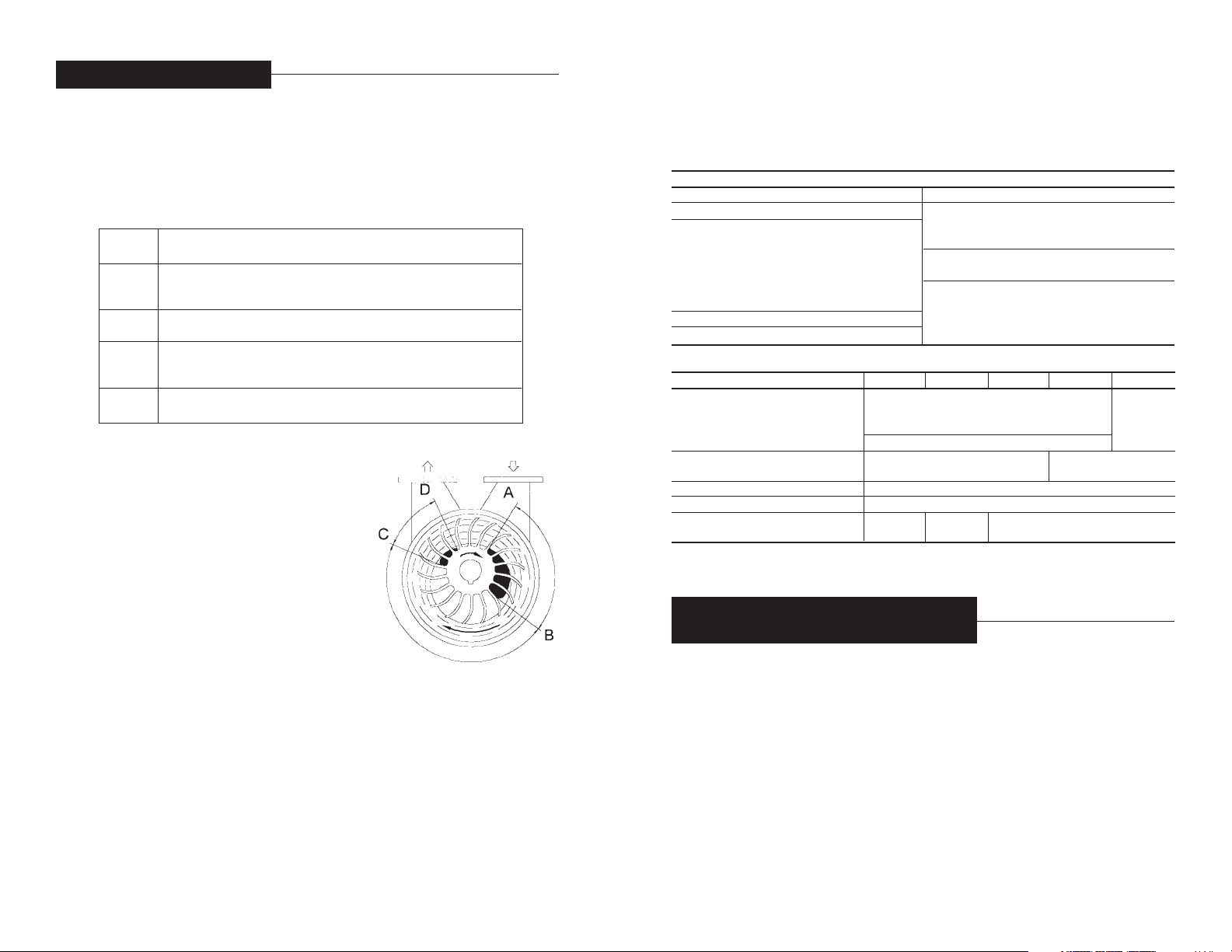
4.1 - PRINCIPLE OF OPERATION
(See figure at side)
The aspirated gas enters the pump chamber A-B
via the pump suction flange. The gas is trapped
between two (2) impeller vanes. The impeller
rotates eccentrically in relation to the centerline of
the liquid ring that, by centrifugal force, assumes
the shape of the impeller casing. The progressive
change of volume between the two (2) vanes, the
impeller hub and the liquid ring first creates a
vacuum and then a compression of the gas in the
B-C area till the gas is discharged, together with a
portion of the liquid, through the discharge port
C-D. The lost liquid must then be replenished.
4.2 - SERVICE LIQUID PROPERTIES
For good operation, the liquid ring pumps must be supplied with a service liquid,
which is clean, non-abrasive and free of any solids. The service liquid temperature should not exceed 80 °C and the gas handled should be maximum 100 °C;
the liquid density should be between 0.8 and 1.2 g/cm3 and the viscosity should
be less than 40 °C (the pump performance will change if the service liquid has
properties different than those of water at 15°C (60°F). All engineering data is
based on the use of 15°C (60°F) as service liquid, see section 17 for additional
information. Contact TRAVAINI PUMPS USA before using liquids with properties
outside the ranges listed above.
– 3 –
T – Manufacturer POMPETRAVAINI
R – Liquid ring pump
H –M and V = Single stage pump
with high vacuum
S = Single stage pump with
medium vacuum
H = Two stage pump with high
vacuum
C – Revision of hydraulic design
80 –Ø Flange size (mm)
750 –Nominal capacity in m
3
/h
C –C =Shaft sealing by mechanical
seal
B = Shaft sealing by stuffing box
M – Monoblock design with motor
flange (upon request)
GH – Material of construction
GH - F - RZ - RA - A3
(see following table)

– 6 –
The pump or assembly must ALWAYS be moved and transported in the horizontal
position. Prior to moving the unit find the following:
•total weight
• center of gravity
• maximum outside dimensions
• lifting points location.
For safe lifting to prevent material damages and/or personal injuries
is recommended to use ropes, or belts properly positioned on the
pump and/or lifting eyebolts and make correct movements.
NOTE: Lifting eyebolts fitted on single components of the assembly
(pump or motor) should not be used to lift the total assembly.
Avoid lifts whereby the ropes or straps, form a triangle with the top angle over 90°
(see fig. 3). The fig. 4 shows several additional examples of lifting to be avoided.
Prior to moving the unit from an installation, always drain any pumped fluid from
the pump, piping and accessories, rinse and plug all openings to prevent spillage.
For instructions to remove the unit from installation see section 15.
– 5 –
OK
NO
Flexible couplings must be properly aligned. Bad alignments will result in coupling
failures and damage to pump and motor bearings.
Assembly instructions for MONOBLOCK design are listed on paragraph 7.3 steps
1, 2, 4, 5, 6.
Assembly instructions for PUMP-MOTOR ON BASEPLATE are listed on paragraph
7.3 steps 7, 1, 8, 5, 9, 10, 11.
For pump driven with V-Belt, please consult TRAVAINI PUMPS USA for fur ther
information.
7.2 - ALIGNMENT PROCEDURES FOR MONOBLOCK AND FOR PUMP/MOTOR
ASSEMBLY ON BASEPLATE.
TRAVAINI PUMPS USA prior to shipment properly aligns the pump/motor assembly.
It is however required to verify the alignment prior to the star t-up. Misalignment
can occur during handling, transportation, grouting of assembly, etc.
For alignment procedures of MONOBLOCK design see paragraph 7.3 steps 3, 4,
5, 6.
For alignment procedure of BASEPLATE design see paragraph 7.3 steps 7, 5, 9,
10, 11.
NOTE:
Coupling sizes and permissible coupling tolerances listed in this manual
are applicable to the particular coupling brand installed by TRAVAINI PUMPS USA
as a standard. For sizes and tolerances of other type of couplings, follow the
instructions given by their respective manufacturer.
7.3 - ALIGNMENT INSTRUCTIONS
NOTE:
Alignment should be done at ambient temperature, with power to the
motor disconnected and following the safety procedures to avoid accidental star ting (see section 2).
Should the pump operate at high temperatures that could upset the coupling alignment, it is necessary to check the alignment to secure proper working operation
at such operating temperatures. It is recommended the use of proper hand protections such as gloves, when carr ying out the operations listed below (schematics for various assemblies are shown).
NOTE:
The following points must be followed with the sequence stated above and
depending upon the type of operation: alignment assembly or alignment verification.
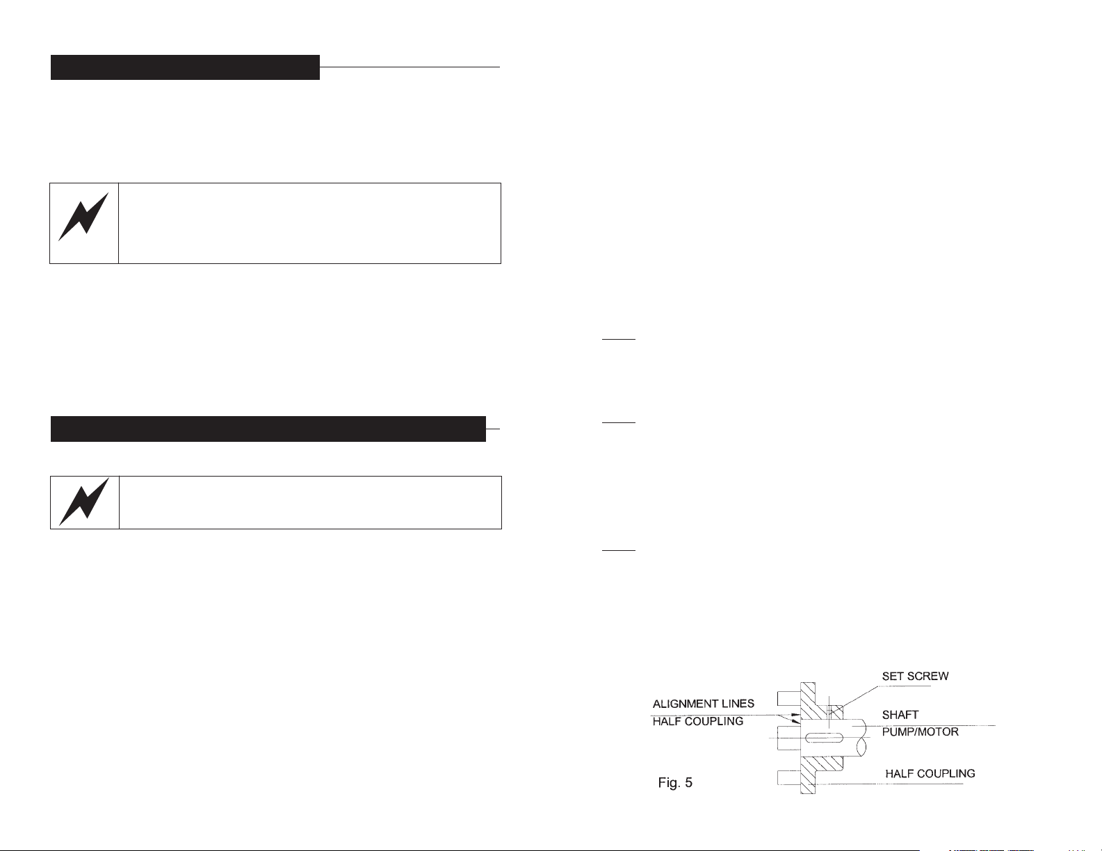
1 - Thoroughly clean motor/pump shaft ends and shaft keys, place the shaft keys
in the proper key way slots and fit the coupling halves in line with the shaft ends.
The use of rubber hammers and even pre-heating of the metal half couplings may
be required (see fig. 5). Lightly tighten the set screws. Verify that both pump and
motor shafts rotate freely.
– 8 –
6 - STORAGE INSTRUCTIONS
After receipt and inspection, if not immediately installed, the unit must be repackaged and stored. For a proper storage proceed as follows:
• store the pump in a location that is closed, clean, dr y and free of vibrations
• do not store in areas with less than 5 °C (41 °F) temperature (for lower
temperature it is necessary to completely drain the pump of any liquids that
are subject to freezing)
FREEZING DANGER!
Where the ambient temperature is less than 5 °C (41°F) it is
recommended to drain the pump, piping, separator, heat exchanger,
etc. or add an anti-freeze solution to prevent damage to the
equipment.
•fill the pump halfway with an anti-rust liquid but compatible with gaskets and
elastomers materials, rotate the pump shaft by hand so that all internal par ts
get wet and then drain the pump of the excessive anti-rust liquid
• plug all openings that connect the pump internals to the atmosphere
•protect all machined surfaces with an anti-rust material (grease, oils, etc.)
• cover the unit with plastic sheet or similar protective material
•rotate pump shaft at least every three months to avoid possible rust build-up
which may result in seizing of the pump.
• pump accessories should be subjected to similar procedure.
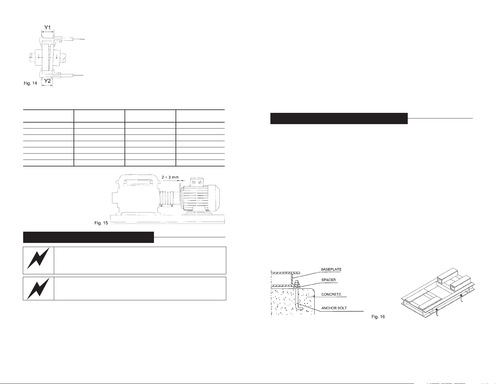
7 - MOUNTING AND ALIGNMENT INSTRUCTIONS
7.1 - ASSEMBLY OF BASE MOUNTED PUMP UNIT
In some cases such as bare pump orders, pumps are shipped with
anti-rust and anti-freeze agents. Ensure pump is thoroughly flushed
and these agents are removed prior to installation.
If the pump has been purchased with a free shaft end, a proper baseplate is
required to mount the pump/motor assembly. The baseplate must be properly
designed for maximum rigidity to prevent vibrations and distortions. It is recommended the use of a fabricated baseplate manufactured with rigid “U” shaped
channel (fig. 16 illustrates an example).
When the pump has been purchased without the electric motor, it is then required
to select the proper motor before proceeding to the installation of the unit. When
selecting a motor the following must be considered:
• maximum power absorbed by the pump over the total operating range
• pump operating speed (RPM)
• available power (Hertz, voltage, etc.)
• motor enclosure type (ODP, TEFC, EX.PR., etc.)
• motor mount (B3, B5, horizontal, vertical, C-flange, D-flange, etc.).
When selecting Flexible couplings the following must be considered:
• nominal motor horsepower
• motor operating speed
• coupling guard must meet safety standards as dictated by OSHA, etc.
– 7 –
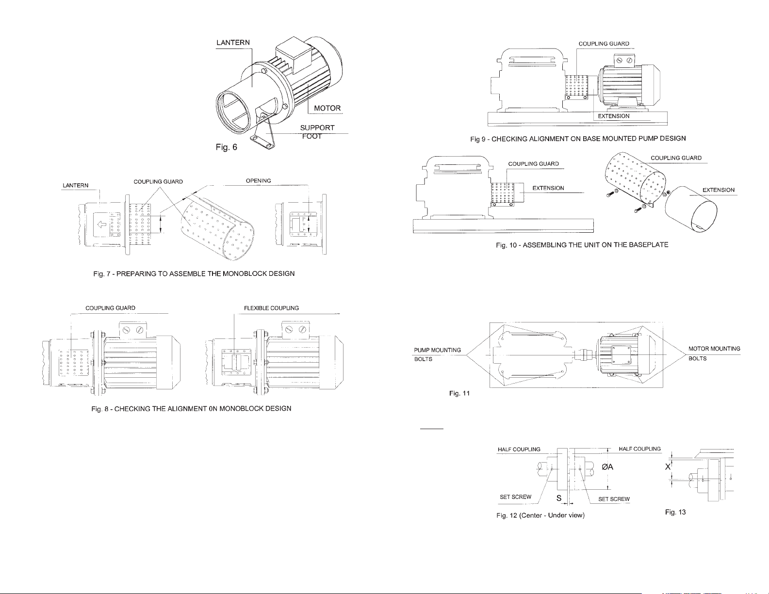
8 - Place the electric motor on the baseplate and bring the two coupling halves
together with approx. 2mm gap between them keeping the motor axially aligned
with the pump shaft. In the event the two shaft heights do not align, proper shimming under the pump or motor feet will be required. Mark the motor and/or pump
anchoring bolt holes. Remove motor and/or pump, drill and tap the holes, clean
and mount pump and/or motor in place and lightly tighten the bolts (see fig. 11).
9 -With a straight edge ruler check the parallelism of the two coupling halves at
several points, 90° from each other (see fig. 13).
NOTE:
Easier and more accurate readings can be attained with instruments such
as Dial Indicators (if readily available).
If the maximum
value of “X” is
higher than that
listed in the table
2 (for the given
coupling size) it
will be required to
correct the alignment by using shims under the pump or motor feet. When the measured values
fall within the tolerances (tolerances only given for “S”), the pump and motor
mounting bolts can be tightened.
– 10 –
2 - Insert the per forated metal sheet coupling
guard inside the lantern so that the coupling
is accessible from one of the lateral openings. Couple the electric motor to the pump
lantern engaging the two coupling halves,
hands may reach the coupling halves through
the lateral opening (see fig. 7) tighten the
assembly with bolts supplied with the unit
and install the supporting foot, when applicable (see fig. 6).
3 - Applying slight hand pressure to the coupling guard, rotate it so that one opening of
the lantern is accessible (see fig. 8).
4 - Rotate by hand the coupling through the lateral opening of the lantern to make
sure the pump is free.
5 - With a feeler gauge, check the distance between the two coupling halves. The
gap value “S” should be as listed on table 2 or as given by the coupling manufacturer. In the event, an adjustment is necessary, loosen the set screws on the
coupling half and with a screw driver move the coupling half to attain the gap “S”
(see fig. 12). Then tighten the set screw and rotate the rotor by hand to make
sure, once more, that there is no obstruction.
6 - Rotate back the coupling guard by hand through the two openings of the lantern
so that both openings are completely covered. This will complete the alignment
verification of the MONOBLOCK design.
7 - Remove the coupling guard and its extension (if there is one) attached to the
pump, by removing the two locking screws (see fig. 9 and 10).
– 9 –
start, to avoid electrical overloads to the motor and mechanical overloads to the
pump. Be sure to replace all safety guards before switching on the electrical
power. If possible check the direction of rotation before the motor is coupled to
the pump but protect the motor shaft to prevent any accidents. When this is not
possible briefly jog the pump to check its direction of rotation (see arrow on pump
for correct rotation). If the direction must be changed two of the three electrical
wire leads must be alternated with each other (at the terminal box or at the motor
starter). Be aware that rotation in the wrong direction and/or pump running dr y
may cause severe pump damage. Electrical instrumentation such as solenoid
valves, level switches, temperature switches, etc. which are supplied with the
pump or systems must be connected and handled in accordance with the instructions supplied by their respective manufacturers. Contact TRAVAINI PUMPS USA
for specific details.
9 - INSTALLATION INSTRUCTIONS
Information to determine the piping sizes and floor space requirements can be
obtained from dimensional drawings and other engineering data. The information
required is:
• size and location of suction and discharge flanges
• size and location of service liquid connection and connections for cooling,
heating, flushing, draining, etc.
• location and size for mounting bolts for monoblock pump and/or baseplate
and/or frame.
In the event additional accessories are required to complete the installation such
as separators, piping, valves, etc. refer to sections 9.2 to 9.8. Proper lifting
devices should be available for installation and repair operations. Pump assembly should be installed in an accessible location with adequate clear and clean
space all around for maintenance, so that an efficient and proper installation can
be made. It is important to have proper room around the unit for ventilation of
motor and air-cooled radiator, if applicable. Avoid installing the unit in hidden locations, dusty and lacking of ventilation. Select a mounting pad that will minimize
vibrations or torsion of the pump baseplate or frame. It is generally preferred to
have a concrete base or sturdy steel beams. It is impor tant to provide adequate
anchor bolting for the pump frame or baseplate to be firmly attached to the foundations (see fig. 16).
Concrete pads and other concrete works must be aged, dr y and clean before the
pump assembly can be positioned in place. Complete all the work relating to the
foundations and grouting of the pump assembly, before proceeding with the
mechanical and electrical portion of the installation.
– 12 –
10 - Angular misalignment can be measured with a
Caliper. Measure the outside coupling dimension at several points (see fig. 14). Find the minimum and maximum width of the coupling, the difference between
these two readings “Y” (Y1-Y2) should not exceed the
value listed in table 2 for the given coupling size.
Should this value be greater it will be necessary to correct the alignment by shimming the pump and/or motor.
Following this operation it is recommended to check
once more the value “X” to make sure that both values
are within the allowed tolerance (see point 9). Make
sure that both set screws on the coupling halves are properly secured.
Table 2
COUPLING GAP PARALLEL ANGULAR
“Ø A” mm “S” mm “X” mm “Y” mm
60 2 to 2.50 0.10 0.20
80 2 to 2.50 0.10 0.20
100 2 to 2.50 0.15 0.25
130 2 to 2.50 0.15 0.25
150 3 to 3.75 0.15 0.30
180 3 to 3.75 0.15 0.30
200 3 to 3.75 0.15 0.30
11 - Install the coupling
guard and its extension (if
applicable) on the pump,
secure the two locking
bolts. The gap between
motor frame and the guard
should not be greater than 2
to 3mm (see fig. 15).
8 - ELECTRICAL CONNECTIONS
Electrical connections must be made exclusively by qualified
personnel in accordance with the instructions from the manufacturer
of the motor or other electrical components and must adhere to the
local National Electrical Code.
FOLLOW ALL SAFETY PRECAUTIONS AS LISTED IN SECTION 2.
BEFORE DOING ANY WORK TO THE INSTALLATION, DISCONNECT
ALL POWER SUPPLIES.
It is recommended that electric motors be protected against overloading by means
of circuit breakers and/or fuses. Circuit breakers and fuses must be sized in
accordance with the full load amperage appearing on the motor nameplate. It is
advisable to have an electrical switch near the pump for emergency situations.
Prior to connecting the electrical wiring, turn the pump shaft by hand to make sure
that it rotates freely. Connect the electrical wiring in accordance with local electrical codes and be sure to ground the motor. Motor connection should be as indicated on the motor tag (frequency and voltage) and as discussed in the motor
instruction manual. It is recommended that motors over 75Hp be wired for soft
– 11 –
 Loading...