

Page 1
Traulsen Refrigeration
SERVICE MANUAL
Instructions For The Troubleshooting And
Repair Of Traulsen SmartChill
Record And Label Printers
RBC50, RBC100, RBC200, RBC200RT,
RBC400 & RBC400RT Blast Chiller Models
®
Control
This manual is prepared for the use of trained Authorized Traulsen Service Agents and should not be used by
those not properly qualied. This manual is not intended to be all encompassing, but is written to supplement
the formal training, on-the-job experience and other product knowledge acquired by Authorized Traulsen
Service Agents. Before proceeding with any work, you should read, in its entirety, the repair procedure you
wish to perform to determine if you have the necessary tools, instruments and skills required to perform the
procedure. Only a trained Authorized Traulsen Service Agent should perform procedures for which you do
not have the necessary tools, instruments and skills. Reproduction or other use of this manual without the
express written consent of Traulsen, is prohibited.
FORM NUMBER TR35911 REV. 9/09 P/N 370-60307-00
Page 2

TABLE OF CONTENTS
I. GENERAL INFORMATION
a-Introduction 1
b-Operation 1
c-Cleaning 1
d-Applicable Models 1
e-Tool Requirements 1
f-Enable-Disable Label Printer 1
II. BASIC SERVICE PROCEDURES & ADJUSTMENTS
a-Check Record Printer Media 2
b-Check Label Printer Media 2
c-Loading The Printer Media 2
d-Running A Test Print 2
III. PRINTER COMPONENT DIAGRAM 2
I. GENERAL INFORMATION
I. a–INTRODUCTION:
A Traulsen Blast Chiller will come standard with one printer, the
record printer. All SmartChill® controls have the option to enable
or disable the use of a second printer, the label printer.
When facing the front of the unit the record printer is located in
the left printer housing and the label printer is in the right printer
housing.
Both printers, record and label, have the same part number
950-60355-00 and are interchangeable with the exception of
any RBC50 models manufactured prior to 2008, with 90 degree
printer boards in which case the part number is 950-60408-00.
I. b–OPERATION:
SmartChill® printers are thermal printers, meaning no ink is required. Upon receipt of a signal from the SmartChill® control,
the printers will print specied data. The record printer ONLY
uses 2 ¼” thermal paper and the label printer ONLY uses 2 ¼”
Traulsen thermal label stock part number 400-60004-00.
The record printer will print power on diagnostics information,
single batch data, and twelve hour data logs.
IV. ADVANCE SERVICE PROCEDURES & ADJUSTMENTS
a-Cutting Wheel Operation 3
b-Check Printer Power-Basic 3
c-Check Printer Power-Advanced 3
d-Check Printer Data Harness 3
e-Interchange Instructions 3
V. FLOW CHART - SERVICE PROCEDURES
& ADJUSTMENTS 4
VI. SMARTCHILL® BOARD DIAGRAM 5
VII. TROUBLESHOOTING 6
I. d–APPLICABLE MODELS:
This manual applies to the following Traulsen models:
RBC50 Undercounter Blast Chill Model
RBC100 Reach-In Blast Chill Model
RBC200 Roll-In Blast Chill Model
RBC200RT Roll-Thru Blast Chill Model
RBC400 Roll-In Blast Chill Model
RBC400RT Roll-Thru Blast Chill Model
NOTE: This manual refers to the above models built
after June 2003, equipped with the SmartChill® control.
For information regarding models built prior to that date
please contact the factory at 800-825-8220.
I. e–TOOL REQUIREMENTS:
• Basic hand tools
• AC/DC VOM
I. f–ENABLE-DISABLE LABEL PRINTER:
The FACTORY SETTINGS MODE allows service personnel to return various control settings to their factory
preset parameters.
The label printer will print single batch product labels, that may
be applied on food containers.
I. c–CLEANING:
Dirt and debris can build up on the feed roller and cutting wheel
cartridge and impede normal operation. Clean only with electric
contact cleaner using a lint free cloth.
-1-
Page 3
I. GENERAL INFORMATION (cont’d)
I. f–ENABLE-DISABLE LABEL PRINTER (cont’d):
To enter from the keypad, press “MORE” from the “MAIN
MENU”. Press “SETUP”, and change the “PASSWORD
(PIN)” to “85”. Press and hold the upper left, upper right
and lower right keys simultaneously. Then release all
keys. Display will read as follows:
Press “NEXT”, this will bring you to the Label Printer
option screen:
II. BASIC SERVICE PROCEDURES
& ADJUSTMENTS (cont’d)
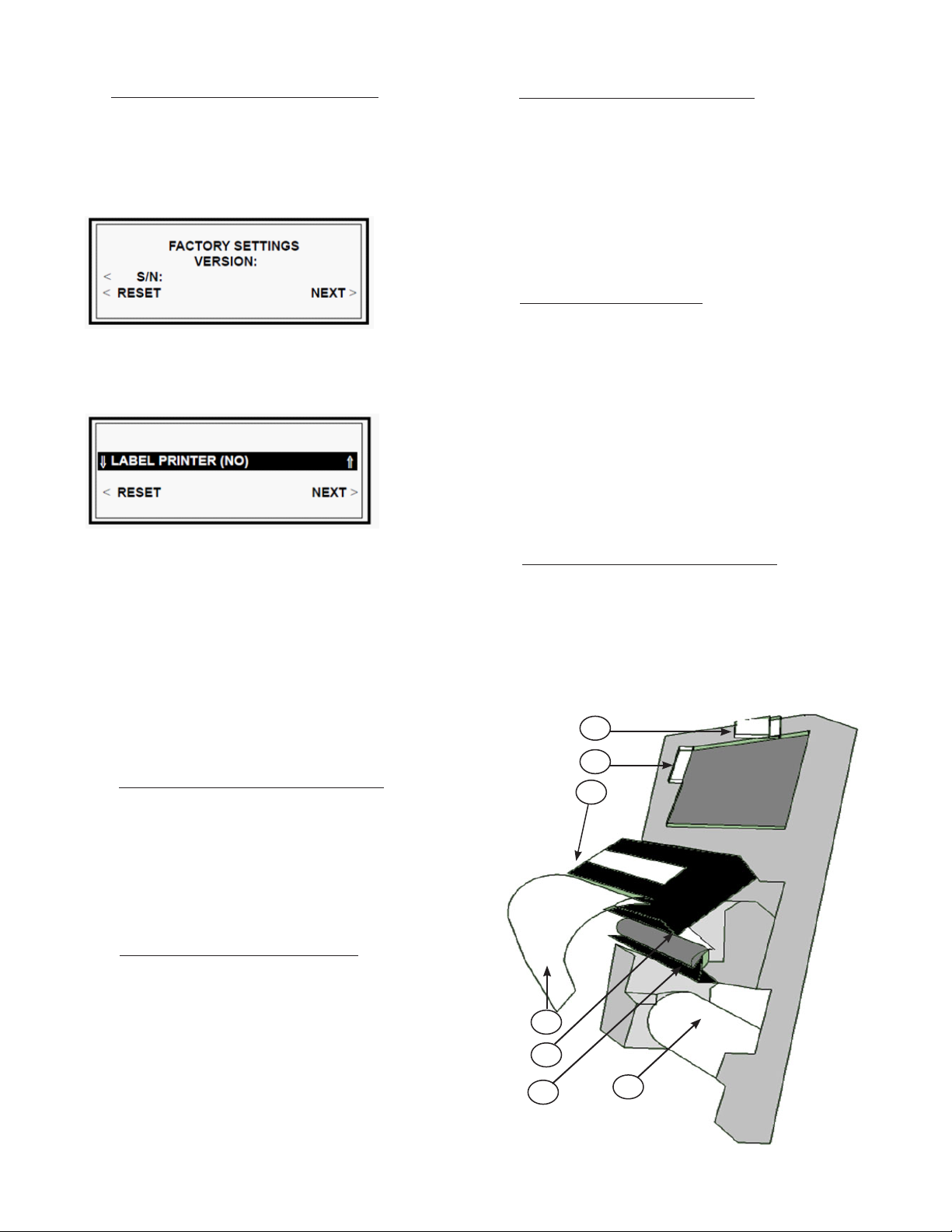
II. c–LOADING THE PRINTER MEDIA:
• Place printer media on spindle (see gure 1; reference 7).
• Fold the end of the printer media to a centered point allows
smoother transition when feeding (see gure 1; reference 4).
• Lift the cutting wheel cartridge (see gure 1; reference 3) and
release the feed roller tension arm (see gure 1; reference 6).
• Feed the printer media over the feed roller (see gure 1; refer
ence 5) and through the cutting wheel cartridge.
NOTE: Thermal coating side must face up.
• Engage feed roller tension arm and cutting wheel cartridge.
II. d–RUNNING A TEST PRINT:
• Start at the “MAIN MENU”
• Press “MORE”
• Press “SET UP”
• Change “PASSWORD (PIN)” to “75”
• Press the top left, top right and the bottom right buttons
simultaneously and release to enter the “SERVICE MENU”
• Press “NEXT”
• Select “PRINTERS”
• Press “RECORD READY” or “LABEL READY” for a test print.
Press the up or down arrow to toggle between “LABEL
PRINTER (NO)” and “LABEL PRINTER (YES)”.
Press “NEXT” until you reach the screen with “EXIT” option. Press “EXIT” then press “YES” to save settings.
II. BASIC SERVICE PROCEDURES
& ADJUSTMENTS:
II. a–CHECK RECORD PRINTER MEDIA:
The record printer must be loaded with 2 ¼” thermal
paper. The thermal side must be facing up.
Verify paper has thermal coating by running a blunt object across the thermal coating. The friction will create
enough heat to leave markings on the thermal coated
side.
II. b–CHECK LABEL PRINTER MEDIA:
The Label printer must be loaded with 2 ¼” Traulsen
label stock, part number 400-60004-00. Labels must
be facing up.
Traulsen label stock can be identied by the ½” or by
¼” black place marker on the top right corner of each
label.
III. PRINTER COMPONENT DIAGRAM
III. a-PRINTER COMPONENT DIAGRAM:
Reference 1=Printer Power Port-Red Harness
Reference 2=Printer Data Port-White Harness
Reference 3=Cutting Wheel Cartridge
Reference 4=Paper Folded To Point For Easy Feed
Reference 5=Feed Roller
Reference 6=Feed Roller Tension Arm
Reference 7=Thermal Paper Or Label Stock
1
2
3
4
5
6
7
-2-
Figure 1
Page 4

IV. ADVANCE SERVICE PROCEDURES & ADJUSTMENTS
IV. a–CUTTING WHEEL OPERATION:
The cutting wheel is located in the cutting wheel cartridge (see
gure1; reference 3; page 2). The cutting wheel moves right to
left to cut paper/labels then resets back to the right.
The cutting wheel must reset all the way back to the right for the
printer to initialize. If the cutting wheel jams the printer will not
initialize and will not print.
If debris is blocking the cutting wheel remove debris and cycle
power. The cutting wheel should reset on its own. If cutting
wheel does not reset, manually reset the cutting wheel by adjusting the plastic Phillips head adjustment screw located on the
left hand side of the cutting wheel cartridge. If the wheel will not
move or is very resistive in movement it is likely it will not reset
properly and the printer must be replaced.
IV. b–CHECK PRINTER POWER-BASIC:
1) The quickest way to verify the printer is receiving power is to
release then re-engage the feed roller tension arm (see gure
1; reference 6; page 2). Any time the feed roller tension arm is
re-engaged the printer should index the printer media approxi-
mately 1/8”. The printer media will also index on system power
up.
2) If the printer media does index when the feed roller tension
arm is engaged and printer still does not print then reference
Section II. a, b, c, & d to check printer media or Section IV. d to
check data cables and SmartChill® control.
IV. c–CHECK PRINTER POWER-ADVANCED (cont’d):
4) If 2 pin connector is secure and has proper voltage
and still does not print, replace printer.
5) If 2 pin connector does not read 8.5VDC check DC
power supply for proper voltage. (Voltages are labeled
on relay board and DC power supply terminals). For
more information on troubleshooting DC power supply
contact Traulsen Service Department at 800-825-8220.
IV. d–CHECK PRINTER DATA HARNESS:
The white harness is the printer data harness. If the
printer indexes when following instructions in Section IV.
b but does not print, check the white data harness (see
gure1; reference 2; page 2) for damage or weak connection.
IV. e–INTERCHANGE INSTRUCTIONS:
Both printers, label and record, are exactly the same
printer and interchangeable. When plugged into PTR
1 ports (see gure 2; reference 1; page 5) on the back
of the SmartChill® board the printer will act as a record
printer. When plugged into PTR 2 ports (see gure 2;
reference 2; page 5) on the back of the SmartChill® board
the printer will act as a label printer.
NOTE: Always inspect all boards and cables for signs of
water damage or corrosion. Corrosion will impede printer
and or control board operation.
3) If the printer media does not index when the feed roller tension arm is engaged reference Section IV. c to further check
printer power.
NOTE: The printer media will not index if the cutting wheel is
jammed.
IV. c–CHECK PRINTER POWER-ADVANCED:
1) The red harness is the power harness for the printer. Ensure
this harness is plugged in securely and shows no signs of dam-
age to both the printer (see gure 1; reference 1; page 2) and
the SmartChill® board (see gure 2; page 5).
2) If the red power cable seems to have a weak connection
tighten the connection and refer back to Section IV. b to check
printer operation.
3) If the red power cable seems to be secure and shows no
signs of damage, check the 2 pin connector, grey and black
wires, on the back of the SmartChill® board (see gure 2; refer-
ence 3; page 5) for 8.5VDC and secure connection.
-3-
Page 5

V. FLOW CHART - SERVICE PROCEDURES & ADJUSTMENTS
No Print
1
Is
Thermal
Paper?
Replace
Printer
Media
NO
YES
3
Does
Printer Have
Power?
Re-feed
Media/Re-
Boot Check
Data Cables
YES
2
Is
Cutting
Wheel
Stuck
Manually
Reset or
Replace
Printer
YES
NO
NO
4
Are Power
Cables
Damaged/
Loose
Replace
/Secure
Damaged
Power
Cables
YES
NO
Replace
Printer
V. FLOW CHART - SERVICE PROCEDURES & ADJUSTMENTS:
Reference 1 (No Print)=Is Printer Media Thermal Paper?
Reference 2 (No Print)=Is Cutting Wheel Stuck?
Reference 3 (No Print)=Does Printer Have Power?
Reference 4 (Replace Printer)=Are Power Cables Damaged or Loose?
Reference 1
Reference 2
Reference 3
Reference 4
-4-
Page 6

VI. SMARTCHILL® BOARD
VI. SMARTCHILL BOARD:
Reference 1=PTR1 Ports - Record Printer
Reference 2=PTR2 Ports - Label Printer
Reference 3=2 Pin Connector - Printer Power
Figure 2
-5-
Page 7

VII. TROUBLESHOOTING
Certain procedures in this section may require electrical and refrigeration system test or measure
ments while power is applied to the cabinet. Exercise extreme caution at all times. If test points
are not easily accessible, disconnect power, attach test equipment and reapply power to test.
Not Printing 1. Check printer media to insure it is the proper type and loaded properly see Sec. II. a, b.
2. Check printer power see Sec. III. b, c, d.
3. Check for water damage or corrosion see Section III. e.
Loading Media 1. Always fold the tip of the media to a point Section III c.
Error Code 1. Check Printer Media.
2. Generic error message indicating a printer has failed to print (printer not specied).
Corrosion 1. Routinely inspect printer boards, cutting wheel cartridges, cables & board for signs of
corrosion.
2 Pin Connector 1. Often after resent service the 2 pin connector (grey and black wires) on the back of the
SmartChill
®
control can become loose or disconnected causing a printer failure.
Verify Printer Power 1. The quickest way to verify a printer has power is to release then re-engage the
tension arm. The printer should index the media about 1/8”.
Printer Fails To Initialize 1. If a printer continues to feed paper with only a few random characters printed every so
often, the printer has failed to initialize. If this happens simply power cycle the control.
Printer Replacement 1. Both printers, record and label, have the same part number 950-60355-00 and are inter
changeable with the exception of any RBC50 models manufactured prior to 2008, with
90
degree printer boards in which case the part number is 950-60408-00.
-6-
Page 8

HOURS OF OPERATION:
Monday thru Friday 7:30 am - 4:30 pm CST
Traulsen
4401 Blue Moud Road Fort Worth, TX 76106
Phone (800) 825-8220 Fax (817) 740-6757
Traulsen Refrigeration
Website: www.traulsen.com
© 2009 Traulsen - All Rights Reserved
 Loading...