

Page 1
Traulsen & Co., Inc.
Quality Refrigeration
OWNER’S MANUALOWNER’S MANUAL
OWNER’S MANUAL
OWNER’S MANUALOWNER’S MANUAL
Instructions for the installation
and maintenance of most Traulsen models as well as
instructions to operate the following special models:
Even-Thaws
Proofers
Proofer/Retarders
Blast Freezers
Fish Files
This Traulsen unit is built to our highest quality standards. We build our refrigerators, freezers and heated
cabinets this way as a matter of pride. This philosophy has made Traulsen the leader in commercial refrigeration since 1938. We thank you for your choice and confidence in Traulsen equipment and we know you
will receive many years of utility from this equipment.
All Traulsen units are placed on a permanent record file with the service department. In the event of any
future questions you may have, please refer to the model and serial number found on the name tag affixed
to the unit. Should you need service, however, call us on our toll free number, 800-825-8220 between 7:30
am and 4:30 pm CST, Monday thru Friday. It is our pleasure to help and assist you in every possible way.
INSTALLER
COMPLETE THE FOLLOWING INFORMATION PRIOR TO UNIT INSTALLATION
INITIAL START DATE: SERIAL NO.
MODEL TYPE:
COMPANY/INDIVIDUAL NAME:
INSTALLER:
SAP DOC REV. 7/01 P/N 375-60185-00
Page 2
TABLE OF CONTENTS
I. THE SERIAL TAG Page 1
II. RECEIPT INSPECTION Page 2
III. INSTALLATION
a-Location Page 2
b-Packaging Page 2
c-Installing Legs or Casters Page 2
d-Shelf Pins Page 2
e-Roll-In Model Installation Page 3
f-Installing The Condensate Evaporator Page 3
g-Remote Installation Page 3
h-Cord & Plug Page 3
i-Power Supply Page 4
j-Wiring Diagram Page 4
k-Compressor Hold Down Provisions Page 4
l-Clearance Page 4
IV. CARE & MAINTENANCE
a-Cleaning The Condenser Page 4
b-Hinge Replacement Page 4-5
c-Replacing The Gaskets Page 5
d-Cleaning The Exterior Page 5
e-Cleaning The Interior Page 5
V. MISC. OPERATIONS
a-Adjusting The Shelves Page 5
VI. OTHER
a-Service Information Page 5
b-Spare Parts Page 5
c-Warranty Registration Page 5
VII. PROOFER & PROOFER/RETARDER MODELS
a-Installation Page 6
b-Proofer Operating Instructions Page 6
c-Operating The Dial Humidistat Page 6-7
d-Retarder Operation Page 7-8
e- Care of Water Tank & Heating Elements Page 8
f-Interior Arrangements Page 8
VIII. EVEN-THAW MODELS
a-Application Overview Page 9
b-Product Loading Guidelines Page 9
c-Starting An Even-Thaw Cycle Page 9
d-Conclusion Of Even-Thaw Cycle Page 9
e-Interior Arrangements Page 9
f-Frequently Asked Questions Page 9-10
IX. FISH FILE MODELS
a-Fish File Application Page 10
b-Special Installation Note Page 10
c-Drawer Pans Page 10
d-Product Loading Page 10
e-Cleaning Page 10
X. BLAST FREEZER MODELS
a-Blast Freezer Application Page 11
b-Special Installation Note Page 11
c-Interior Arrangements Page 11
d-Blast Freezing vs. Blast Chilling Page 11
e-Normal Operation Page 11
f-Defrost Page 11
g-Blast Chill Operation Page 11
h-Proper Packaging Page 11
XI. TROUBLE SHOOTING GUIDE Page 12
XII. WARRANTY INFORMATION Page 13
XIII. INDEX Page 14
FORT WORTH, TX.
SERIAL MODEL
VOLTS Hz PH
TOTAL CURRENT AMPS
MINIMUM CIRCUIT AMPS
MAXIMUM OVERCURRENT PROTECTION AMPS
LIGHTS WATTS
HEATERS AMPS
REFRIGERANT TYPE OZ
DESIGN PRESSURE HIGH LOW
REFRIGERANT TYPE OZ
DESIGN PRESSURE HIGH LOW
370-60294-00 REV (A)
-1-
I. THE SERIAL TAG
The serial tag is a permanently affixed sticker on
which is recorded vital electrical and refrigeration data
about your Traulsen product, as well as the model
and serial number. This tag is located in the upper
right interior compartment on all reach-in/pass-thru
and roll-in/roll-thru refrigerator, freezer and dual-temp
models. For hot food and proofer models, this tag is
located on the top of the unit behind the louvers to
protect it from the heat.
READING THE SERIAL TAG
• Serial = The permanent ID# of your Traulsen
• Model = The model # of your Traulsen
• Volts = Voltage
• Hz = Cycle
• PH = Phase
• Total Current = Maximum amp draw
• Minimum Circuit = Minimum circuit ampacity
• Lights = Light wattage
• Heaters = Heater amperage (Hot Food units only)
• Refrigerant = Refrigerant type used
• Design Pressure = High & low side operating
pressures and refrigerant charge
• Agency Labels = Designates agency listings
Page 3
II. RECEIPT INSPECTION
III. INSTALLATION (continued)
All Traulsen products are factory tested for performance and are free from defects when shipped. The
utmost care has been taken in crating this product to
protect against damage in transit. All interior fittings
have been carefully secured and the legs or casters
are boxed and strapped inside to prevent damage.
Door keys will be attached to the handle with a nylon
strip. The handle is protected by an easily removable
nylon netting.
You should carefully inspect your Traulsen unit for
damage during delivery. If damage is detected, you
should save all the crating materials and make note
on the carrier’s Bill Of Lading describing this. A freight
claim should be filed immediately. If damage is subsequently noted during or immediately after installation, contact the respective carrier and file a freight
claim. Under no condition may a damaged unit be returned to Traulsen & Co. without first obtaining written permission (return authorization).
III. INSTALLATION
III. a - LOCATION:
Select a proper location for your Traulsen unit, away
from extreme heat or cold. Allow enough clearance
between the unit and the side wall in order to make
use of the door stay open feature at 120° (self-closing
feature operates up to 90°). The door(s) must be able
to open a minimum of 90° in order to make use of the
maximum clear door width available.
III. b - PACKAGING:
All Traulsen units are shipped from the factory bolted
to a sturdy wooden pallet and packaged in a durable
cardboard container. The carton is attached to the
wooden skid with the use of large staples. These
should first be removed to avoid scratching the unit
when lifting off the crate.
Most exterior stainless steel surfaces have a protective vinyl covering to prevent scratching during manufacturing, shipping and installation. After the unit is
installed in place of service, remove and discard the
covering from all surfaces.
III. c - INSTALLING LEGS OR CASTERS:
6” high stainless steel legs are supplied standard for
all Traulsen reach-in and pass-thru units. Casters in
lieu of legs are available as an optional accessory for
the same models. These are shipped from the factory
packed inside a cardboard box which is strapped to
one of the shelves. Remove the nylon strap and open
the box, it should contain either four (4) legs or four
(4) casters and sixteen (16) bolts.
WARNING: THE CABINET MUST BE BLOCKED AND
STABLE BEFORE INSTALLING LEGS OR CASTERS.
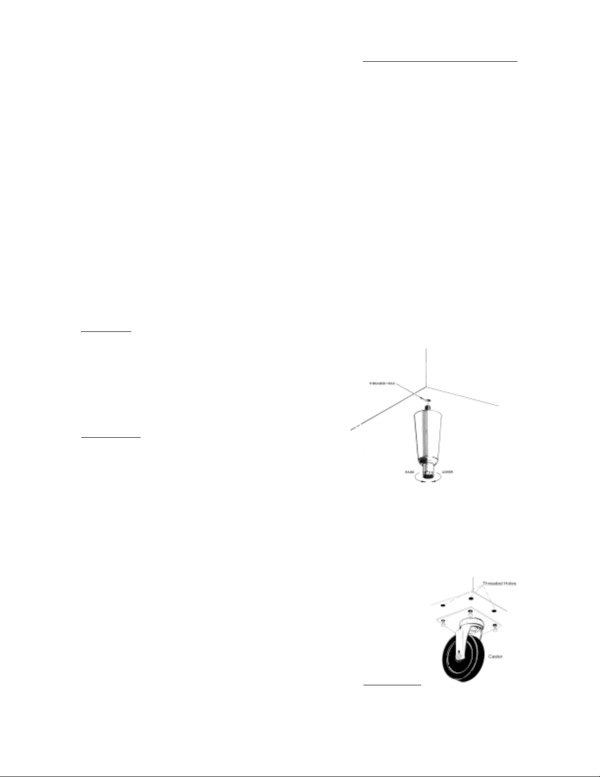
To install the legs or casters, first raise and block the
reach-in a minimum of 7” from the floor. For installing legs, thread the legs into the threaded holes on
the bottom of the cabinet (see figure 1). Be certain
that all legs are tightly secured (legs and casters
should be tightened to 300 inch/pounds, max). When
the unit is set in its final position, it is important for
proper operation that the unit be level. The legs are
adjustable for this purpose, turn the bottom of the leg
counter-clockwise to raise it, clockwise to lower it.
Level the unit from front to back as well as side to side
in this manner, using a level placed in the bottom of
the cabinet.
Fig. 1
Please note that Traulsen units are not designed to be
moved while on legs. If the unit requires moving, a
pallet jack or forklift should be used to prevent damage. For installing casters, the casters are “plate”
type, and require the use of four (4) bolts each to secure them firmly to the cabinet bottom at each corner
(see figure 2). The caster bolts are tightened using a
1/2” socket wrench.
To remove the wooden pallet, first if at all possible, we
suggest that the cabinet remain bolted to the pallet
during all transportation to the point of final installation. The bolts can then be removed with a 3/4” socket
wrench. Avoid laying the unit on its front, side or
back for removal of the pallet.
NOTE: Traulsen does not recommend laying the unit
down on its front, side or back. However, if you must
please be certain to allow the unit to remain in an upright position afterwards for 24 hours before plugging
it in so that the compressor oils and refrigerant may
settle.
Fig. 2
III. d - SHELF PINS:
The unit is supplied with shelves and shelf pins installed. Check all shelf pins to assure they are tightened down as they may have come loose during shipping. Rotate the pins clockwise until they are secured
against the side of the cabinet.
-2-
Page 4
III. INSTALLATION (continued)
III. e - ROLL-IN MODEL INSTALLATION:
Roll-In cabinets set on the floor require the floor area
to be flat and level. In addition, after the cabinet is set
in place, sealant should be used around the perimeter
of the base to comply with National Sanitation Foundation requirements (see figure 3). After sealing the
unit, the enclosed ramp should then be installed.
SEALING BASE OF ROLL-IN MODELS
A SEALANT MUST BE USED
AROUND THE PERIMETER OF THE
BASE OF CABINET AS SHOWN TO
FULLY COMPLY WITH SANITARY REQUIREMENTS.
A RECOMMENDED SEALANT IS
DOW CORNING SILASTIC RTV #732
Fig. 3
A stainless steel threshold ramp(s) is included to facilitate rolling in racks. It is shipped wrapped in brown
paper and secured to the rack guides inside the cabinet. To secure it in place, remove the two thumb
screws in the breaker strip near the bottom door opening. Next, loosen the thumb screws located along the
floor at the threshold. Place the ramp(s) on top of the
loosened thumb screws and secure tabs on each end
to breaker strips with thumb screws previously removed. After installing the ramp(s), it too should be
sealed to the floor.
Bumper strips are secured to the back of Roll-In models with thumb screws. Loosen these and make them
finger-tight to conform with the requirements of the
National Sanitation Foundation (NSF).
III. f - INSTALLING THE CONDENSATE EVAPORATOR:
A condensate evaporator is normally supplied on all
self-contained models (remote models require provision of either a floor drain or an optional condensate
evaporator). On those models with the evaporator coil
compartment located on the top of the unit, the condensate evaporator is also secured to the top of the
cabinet. Check that the condensate pan is under the
drain tube.
Some models, such as one-section dual-temperature
reach-in refrigerator/freezers, are supplied with a bottom-mounted electric condensate evaporator. This is
shipped in a cardboard carton secured to the cabinet
interior, and must be installed prior to use.
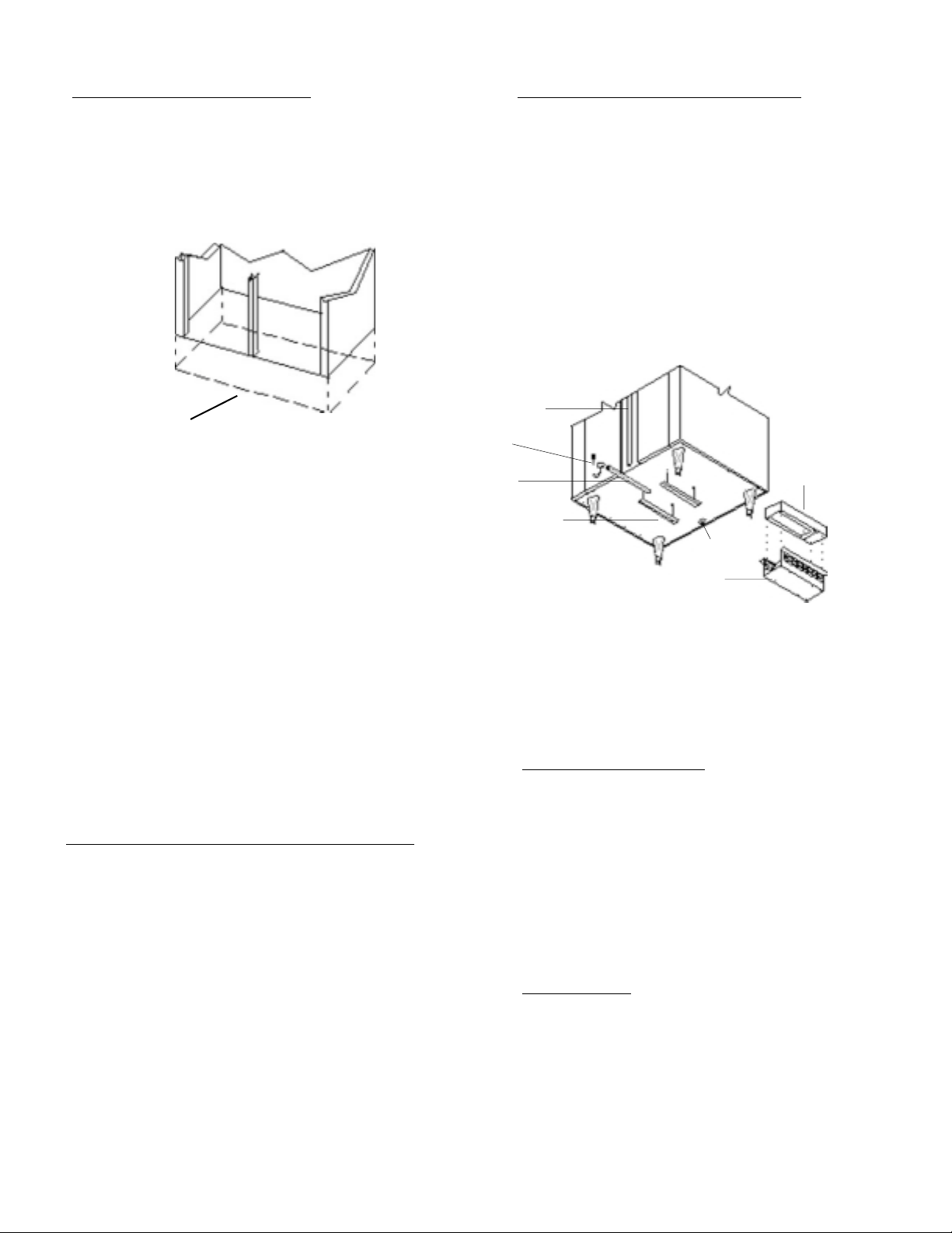
After the cabinet has been uncrated and the legs/casters attached, you must install the bottom-mounted
electric condensate evaporator. Locate the four (4)
III. f - INSTALLING THE CONDENSATE EVAP (cont’d):
holes on the exterior bottom towards the rear of the
cabinet. Then, using the four (4) screws provided, attach the mounting rails to the cabinet bottom (the end
flange is to be up and be facing towards the cabinet
rear). Next, place the heater into the heater bracket
(note the enclosed springs are only to be used when
the heater is placed on the floor). Slide heater and
bracket into the mounting rails. Plug the supplied cord
into both the heater on one end, and the electrical
outlet provided on the cabinet exterior bottom towards
the front (see figure 4). Screw the “U-Trap” on to the
drain line located on the rear of the cabinet and then
screw the drain extension into the “U-Trap.”
Drain
Line
U-Trap
Drain
Extension
10-32 x 3/8 Screw (4)
Mounting Rails
BMCE
Receptacle
Heater
Bracket
Fig. 4
A remote model is normally supplied configured for
condensate to be run to a floor drain unless purchased
with a condensate evaporator. The installer is responsible for making the required extension to the floor
drain in accordance with good practice and local regulations.
III. g - REMOTE INSTALLATION:
Remote models are supplied without compressors,
solenoid valves, etc. The correct voltage, amp listing
and refrigerant are listed on the unit’s serial tag. It is
the responsibility of the installer to specify and supply the correct size compressor(s) based upon this
information and on-site requirements. Refrigerant line
installation must be done in accordance with good
practice and local regulations. See section “III. g” for
information concerning condensate removal for remote models.
III. h - CORD & PLUG:
Most self-contained models are supplied with a cord
& plug attached. It is shipped coiled at the top of the
cabinet, secured by a nylon strip. For your safety and
protection, all units supplied with a cord and plug include a special three-prong grounding plug on the service cord. Select only a dedicated electrical outlet with
grounding plug for power source. NOTE: Do not under any circumstances, cut or remove the round
grounding prong from the plug, or use an extension
cord.
-3-
Electric
Heater
Page 5
III. INSTALLATION (continued) V. CARE & MAINTENANCE (cont’d)
III. i - POWER SUPPLY:
The supply voltage should be checked prior to connection to be certain that proper voltage for the cabinet wiring is available (refer to the serial tag to determine correct unit voltage). Make connections in accordance with local electrical codes. Use qualified
electricians.
Use of a separate, dedicated circuit is required. Size
wiring to handle indicated load and provide necessary overcurrent protector in circuit (see amperage
requirements on the unit’s serial tag).
III. j - WIRING DIAGRAM:
Refer to the wiring diagram for any service work performed on the unit. Should you require one, please
contact Traulsen Service at (800) 825-8220, and provide the model and serial number of the unit involved.
III. k - COMPRESSOR HOLD DOWN PROVISIONS:
To protect the compressor during transit, some selfcontained Traulsen models have compressors tightened down at the factory. The hold down bolts used
to tighten these must be loosened before operation
to allow the vibration eliminators to funtion properly.
Failure to loosen the hold down bolts could result in
refrigerant line leakage, vibration and noise. Check
the top to be sure all factory installed blocking (if used)
is also removed. Likewise, check the compressor enclosure of bottom mounted units (RFD/AFD models)
to be sure all packing is removed and that compressors secured to the base of condensing unit are free
to operate on their vibration eliminators.
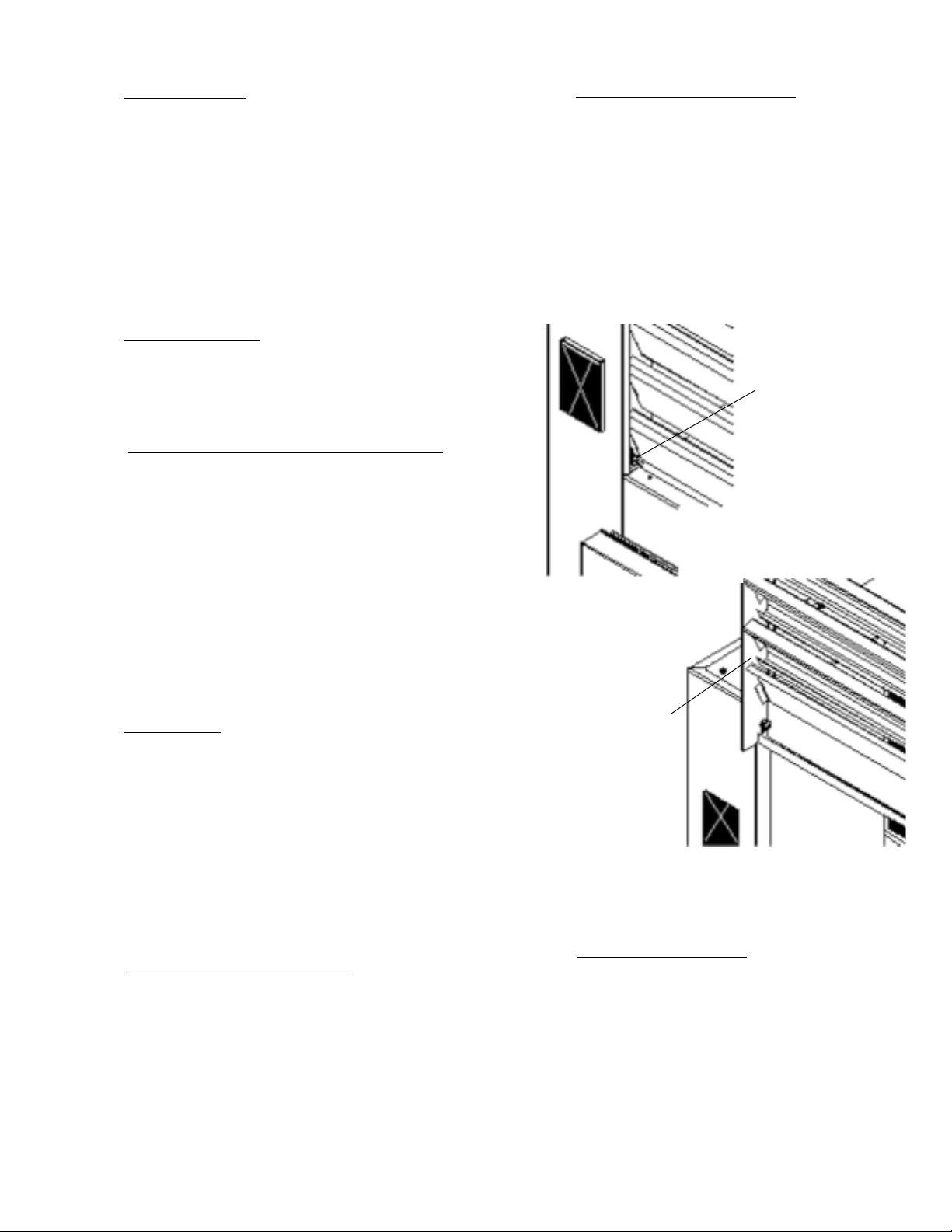
IV. a - CLEANING THE CONDENSER (cont’d):
two screws located on both sides at the bottom of the
louver assembly (see figure 6). Once the screws are
removed, the panel can be pivoted upwards allowing
full access to the front facing condenser (see figure
7). Vacuum or brush any dirt, lint or dust from the
finned condenser coil, the compressor and other cooling system parts. If significant dirt is clogging the condenser fins, use compressed air to blow this clear.
Lower louver assembly and replace the screws to hold
it in place.
Fig. 6
Remove
Screws
III. l - CLEARANCE:
In order to assure optimum performance, the condensing unit of your Traulsen unit MUST have an adequate
supply of air for cooling purposes. Therefore, the
operating location must either have a minimum of 12”
clearance overhead of the condensing unit or allow
for unrestricted air flow at the back of the unit. Clearance of at least 12” above is required in order to perform certain maintenance tasks.
IV. CARE & MAINTENANCE
IV. a - CLEANING THE CONDENSER:
The most important thing you can do to insure a long,
reliable service life for your Traulsen is to regularly
clean the condenser coil.
The condensing unit requires regularly scheduled
cleaning to keep the finned condenser clean of lint
and dust accummulation. Keeping the condenser
clean allows the cabinet to operate more efficiently
and use less energy. To clean the condenser, first
disconnect electrical power to the cabinet and lift up
the front louver as sembly. To lift this, remove the
Lift-Up Louver
Fig. 7
Assembly
WARNING: DISCONNECT ELECTRICAL POWER
SUPPLY BEFORE CLEANING ANY PARTS OF THE
UNIT.
IV. b -
HINGE REPLACEMENT:
Both the door and hinge can be easily removed from
the cabinet. To remove the door, remove the plug at
the bottom of the top hinge. Inside the hinge there is
a small screw which secures the door in place. Remove this with a flat head screwdriver and the door
can then be lifted off the hinge. To remove the door
portion of the hinge from the door, lift off the hinge
cover and then remove the three Phillips head screws
which secure the hinge in place on the door. To remove the cabinet portion of the hinge, remove the three
Phillips head screws which hold it in place. On solid
-4-
Page 6

IV. CARE & MAINTENANCE (cont’d)
V. MISC. OPERATIONS
IV. b - HINGE REPLACEMENT:
door units, the top hinge(s) contains a microswitch
for controlling the interior lighting.
To reassemble the hinge reverse the previous procedure.
IV. c - REPLACING THE GASKETS:
To remove the gasket to be replaced, grasp it firmly
by one corner and pull it out. Before attempting to
install a new gasket, both the unit and the gasket itself must be at room temperature. Insert the four corners first by using a rubber mallet (or hammer with a
block of wood). After the corners are properly inserted,
work your way towards the center from both ends by
gently hitting with a mallet until the gasket is completely seated in place (see figure 8 for proper gasket
placement).
Inside Door Panel
○○○
Gasket Assembly
○○○
Fig. 8
Vertical Gasket
Retainer
○○○
NOTE: The gasket may appear too large, but if it is
installed as indicated above it will slip into place.
V. a - ADJUSTING THE SHELVES:
For shelves mounted on pins, first select the desired
location and remove the white plastic covers in the
interior back and sides by rotating them counter-clockwise. Remove the shelf pins by rotating them counterclockwise. Install the pins in the desired location by
rotating clockwise. Make sure the pin is securely tightened down. Do not over tighten. Slide the shelf into
its new position, and replace the white plastic covers
into the holes vacated by the shelf pins.
VI. OTHER
VI. a - SERVICE INFORMATION:
Before calling for service, please check the following:
Is the electrical cord plugged in?
Is the fuse OK or circuit breaker on?
Is the power switch “ON”?
If after checking the above items and the unit is still
not operating properly, please contact an authorized
Traulsen service agent. A complete list of authorized
service agents was provided along with your Traulsen
unit. If you cannot locate this, you may also obtain the
name of a service agent from the Tech Service page of
our website: www.traulsen.com.
IV. d -
CLEANING THE EXTERIOR:
Exterior stainless steel should be cleaned with warm
water, mild soap and a soft cloth. Apply with a dampened cloth and wipe in the direction of the metal grain.
Avoid the use of strong detergents and gritty, abrasive cleaners as they may tend to mar and scratch the
surface. Do NOT use cleansers containing chlorine,
this may promote corrosion of the stainless steel.
Care should also be taken to avoid splashing the unit
with water, containing chlorinated cleansers, when
mopping the floor around the unit.
For stubborn odor spills, use baking soda and water
(mixed to a 1 TBSP baking soda to 1 pint water ratio).
IV. e - CLEANING THE INTERIOR:
For cleaning both stainless steel and anodized aluminum interiors, the use of baking soda as described in
section “IV. d” is recommended. Use on breaker strips
as well as door gaskets. All interior fittings are removable without tools to facilitate cleaning.
If service is not satisfactory, please contact our inhouse service department at:
Traulsen & Co., Inc.
4401 Blue Mound Road
Fort Worth, TX 76106
(800) 825-8220
Traulsen & Co., Inc. reserves the right to change specifications or discontinue models without notice.
VI. b - SPARE PARTS:
Spare or replacement parts may be obtained through
a parts supplier or one of our authorized service agents.
A complete list of authorized service agents accompanies this manual and is also posted on our company’s
official website @ www.traulsen.com.
VI. c - WARRANTY REGISTRATION:
For your convenience, the warranties on your new
Traulsen unit may be registered with us by one of two
methods. Completing the enclosed warranty card
(shipped with the unit), or by filling out the on-line
warranty registration form located on the Technical Service page of our website (www.traulsen.com).
-5-
Page 7

VII. SPECIALTY PRODUCTS - PROOFER/PROOFER RETARDER MODELS
VII. a - INSTALLATION:
MECHANICAL CONNECTION: For plumbing, connect
water supply to inlet strainer as marked on top of cabinet. This connection should be made with a 3/8” male
NPT connector. Water supply pressure should 50 to
80 PSI for best operation.
The drain connector located at the top rear of the cabinet should be made with a 1/2” NPT drain line which
should be connected to either a floor drain or sink
connection. A back flow prevention device (vacuum
breaker) must be used in the water supply line to this
unit.
CAUTION: Any restriction in the drain line could cause
overflow conditions. It is imperative that the 1/2” NPT
fitting be used and the drain line not be reduced in
diameter. If plastic is used, care must be taken to avoid
collapsing the tubing.
ELECTRICAL CONNECTIONS: The Traulsen Proofer
model requires two separate electrical connections.
The first connection is to operate the heater and humidifier. This connection will either be 208/60/1 or 230/
60/1.
Please note electrical information for each cabinet at
given voltage.
PRI132H
Voltage 208/60/1 230/60/1
Amps 21.5 24.0
Watts 4400 5500
PRI232H
Voltage 208/60/1 230/60/1
Amps 30.0 33.5
Watts 6100 7700
PRI332H/PRR232HUT
Voltage 208/60/1 230/60/1
Amps 30.0 33.5
Watts 6100 7700
The second connection is a standard 115/60/1 to operate the control circuits. When connecting a 115 volt
power supply to the cabinet, be sure to connect neutral to white cabinet wire and “live” wire to cabinet
black wire. Reversal of polarity will cause inconsistent operation. Electrical information on this connection is the same for each proofer cabinet.
PRI PRR
Voltage 115/60/1 115/60/1
Amps 3.0 13.5
Watts 500 2100
VII. b - PROOFER OPERATING INSTRUCTIONS:
The Traulsen proofer is designed to automatically flush
out the water tank once every 24 hours. The operator
should select a flush time when the unit is not proofing.
This unit displays the time of day and temperature of
the unit simultaneously. When the proofer is activated
both the time of day and the flush time must be adjusted.
SETTING THE CLOCK:
A-TIME OF DAY - When the unit is initially activated
the time of day is shown as 12 p.m. Use a pointed
object and insert into the fast or slow openings to advance the time of day. NOTE: P.M. is indicated by a
LED dot in the upper left corner of the time display.
B-FLUSH TIMER - Insert a pointed object into the flush
opening to display the flush time. While the flush time
is being displayed the fast or slow openings should
be used to advance to the desired flush time.
Once the time clock has been set the unit is ready for
operation:
1) Adjust the temperature control to the desired
temperature
2) Adjust the humidity control to the desired
humidity.
To activate the unit turn ON the lower switch and then
the control switch. Let the unit reach the temperature
selected.
HEATER THERMOSTAT: When adjusting the heater
thermostat, keep in mind that the heater element does
not cool instantly. There is an override in temperature
of approximately 9 to 12 degrees. This may vary, depending on location, and the thermostat may have to
be adjusted. Once the unit is warmed up to the desired temperature, you will notice that the temperature will stabilize and not vary significantly.
VII. c - OPERATING THE DIAL HUMIDISTAT
The Traulsen humidifier is controlled by a dial humidistat (R.H.). Adjust dial selector for proper level of
humidity. The humidity setting should be 2 to 3 percent below desired setting. The humidifier, in addition to creating humidity in the cabinet, will also create heat. Activate the power switch to the control
heater element. The level of desired humidity should
be based upon product being proofed. If however, you
are utilizing one level of humidity for all products, it is
not necessary to readjust the humidistat each time the
cabinet is turned on.
-6-
Page 8

VII. SPECIALTY PRODUCTS - PROOFER/PROOFER RETARDER MODELS (cont’d)
VII. c - OPERATING THE DIAL HUMIDISTAT (cont’d):
When the desired temperature and humidity settings
are achieved, the white mode indicating lights will go
OFF and you are now ready to proof your product. The
mode lights indicate the various stages of operation
during the proofing process.
AMBER - “LOWER LEVEL” Will be illuminated during
normal operation. Will only turn off when heater water level is below minimum safety level or at start-up.
WHITE - “THERMOSTAT” Will be illuminated when
cabinet is not at set temperature. When cabinet
achieves set temperature, the light will turn off.
RED - “TROUBLE” Will illuminate whenever the water
level is below minimum safe level. It will also be on at
start-up for approximately 30 seconds. When the red
light illuminates, power to the heaters is turned off.
This light is also lit during the flush period until the
units water level returns to normal.
GREEN - “WATER LEVEL” Will be illuminated when
the water pan is full. This light will turn off when the
solenoid valve opens to replenish the water pan.
WHITE - “HUMIDISTAT” Will be illuminated when cabinet is not at set humidity. When the cabinet reaches
the set point this light will turn off.
VII. d - RETARDER OPERATION:
Additional control features for use with model
PRR232HUT only.
RETARD MODE: When in retard mode, the refrigeration system will maintain the cabinet temperature be-
tween 35° to 40° F. This temperature can be adjusted
through use of the temperature control, located inside
the unit mounted on the front of the evaporator coil
housing. To lower the cabinet temperature, turn the
control knob clockwise. To raise the temperature, turn
the knob counter-clockwise.
TIME DELAY: The Traulsen proofer/retarder cabinet is
supplied equipped with a time delay. When the unit is
in automatic operation, this time delay shuts the unit
down for up to one hour when switching from RETARD
to PROOF mode. This allows the cabinet to gradually
rise in temperature before the air and water heaters
come on.
For the best performance, it is recommended that this
time delay be used. However, a time delay override
allows the user to bypass the relay, and the unit will
go from RETARD directly into PROOF. This is accomplished by placing the delay bypass switch in the “ON”
position.
VII. d AUTOMATIC MODE/24 HOUR TIMER - The Traulsen
proofer retarder cabinet is designed to allow both automatic and manual operation. With the function
switch in the “AUTO” position, a 24-hour timer automatically switches between PROOF and RETARD
modes at preset times daily.
To set these switching times, carefully pull the front
protective cover (clear plastic) from the timer, which
is located on the front panel. These should be one
green “ON” pin and one red “OFF” pin on the timer
dial, as well as two spares for each in the top right
hand corner. Simply pull the red “OFF” pin from the
outside ring of the dial and place it in the position corresponding to the time that the cabinet should switch
out of RETARD. NOTE: White portion of the dial corresponds to daytime hours; black portion corresponds
to nighttime hours.
If the time delay is not bypassed, the cabinet will go
into a waiting period and then switch into PROOF
mode. Therefore, the “OFF” pin should be set at least
one hour and thirty minutes before the cabinet is ready
to proof. Of course, this will vary with conditions and
the user should find the best time for application.
The “ON” pin should be placed at the time when the
unit should switch out of PROOF. When the pressure
in the refrigeration system is in the operating range,
the system will start and soon come down to standard retarding temperatures ( 37
necessary for this function of operating conditions
(proof temperature, room temperature, etc.) and will
vary.
Once both pins have been properly placed, set the
correct time of day. This is accomplished by turning
the center knob clockwise until the correct hour is indicated at the white marker in the left-hand corner. Now
adjust for correct minutes, which are indicated by the
pointer in the interior cut out on the dial. The timer
runs independent of the control circuits, and should
only need adjustment in the event of a power failure.
1. Set the 24-hour timer for the correct time of day
2. Set pins for desired switching times on 24-hour time
3. Choose time delay bypass; “ON” or “OFF”
4. Set mode switch for “AUTO”
5. Set desired proof temperature and humidity
6. Place control switch in the “ON” position
The unit will now run automatically.
RETARDER OPERATION (cont’d):
° to 42° F). The time
TO SET THE UNIT FOR AUTOMATIC OPERATION:
-7-
Page 9

VII. SPECIALTY PRODUCTS - PROOFER/PROOFER RETARDER MODELS (cont’d)
VII. d - RETARDER OPERATION (cont’d):
MANUAL OPERATION - The Traulsen proofer retarder
can also be used in either PROOF or RETARD mode,
regardless of what the 24-hour timer is set for. By
switching manually to PROOF or RETARD, the cabinet can be run as needed without disturbing the preset schedule you have the 24-hour timer set for.
Amber
“Lower Level”
Light
The Proofer Control
White
“Thermostat
Indicator”
Light
Red
“Trouble”
Light
Green
“Water Level”
Light
White
“Humidistat
Indicator”
Light
VII. e - CARE OF WATER TANK & HEATING ELEMENTS:
The automatic flush system on the Traulsen proof cabinet will help minimize the amount of cleaning necessary to maintain an accurate and consistent operation
of this cabinet. Because water conditions vary from
location to location, we recommend that the tank cover
be removed and the interior of the water tank, along
with the heating elements, be cleaned with a soft nylon bristled brush. We recommend cleaning twice a
year or as conditions dictate. Replace tank cover before placing proof cabinet back into operation. If your
area has extremely hard water, a local water treatment
expert should be consulted. It is important to note
that after treatment the water should not be deionized.
A simple zeolite conditioner is usually the best system. Use of an in-line cartridge will reduce the frequency of cleaning the heating coil, but remember to
frequently replace the cartridge.
VII. f -
INTERIOR ARRANGEMENTS:
Traulsen proofer and proofer retarder models are designed to accommodate roll-in bakery racks. See below for size and capacities.
Model PRI132H can accommodate one (1) roll-in rack
with a maximum size, with wheels inboard of frame, of
27” wide by 29” deep by 72” high.
Model PRI232H can accommodate two (2) standard 18”
x 26” pan racks or two (2) 23” x 23” donut screen racks.
Model PRI332H can accommodate three (3) standard
18” x 26” pan racks or two (2) 23” x 23” donut screen
racks.
Blower
ON/OFF
Switch
Blower
Power
Switch
Delay
Bypass
Switch
Mode
Switches
OFF
TEMP
“Flush
Indicator”
Light
Traulsen
Thermostat
FLUSH
102.5 F 11:30
TEMPERATURE PM TIME
LOWER LEVEL TROUBLE
BLOWER
ON OFF
CONTROL
The Proofer/Retarder Control
White
“Thermostat
Indicator”
Light
DELAY
BYPASS
CONTROL
ON OFF
Amber
“Lower Level”
Light
OFF
Thermostat
Red
“Trouble”
Light
Traulsen
FLUSH
102.5 F 11:30
TEMPERATURE PM TIME
HOUR
FLUSH MINUTE
Flush Time
&
Time of Day
Adjustment
Ports
“Water Level”
HOUR
FLUSH MINUTE
Flush Time
&
Time of Day
Adjustment
Ports
WATER
LEVEL
Green
Light
Humidistat
Control
Humidistat
Control
HUMIDISTAT
White
“Humidistat
Indicator”
Light
HUMIDISTAT
Model PRR232HUT can accommodate two (2) standard
18” x 26” pan racks or two (2) 23” x 23” donut screen
racks.
-8-
Page 10

VIII. SPECIALTY PRODUCTS - EVEN-THAW MODELS
VIII. a - APPLICATION OVERVIEW:
The Even-Thaw is designed to thaw product at safe
temperatures. By keeping the cabinet temperature
from rising above 40o F, the Even-Thaw inputs small
amounts of heat while moving large volumes of air
around the product. This design allows the product
to thaw at temperatures that minimize bacteria growth.
When in Even-Thaw mode, the refrigeration system is
disabled and a second control adds enough heat to
keep the cabinet at the upper limit of normal refrigerator temperatures. The rate at which the frozen product absorbs heat gradually slows as it warms. During
the Even-Thaw process, the unit will continue to operate in this mode (refrigeration OFF, blower and heater
ON) until the product being thawed can no longer absorb the heat as fast as it is being put into the cabinet.
When this happens, the air temperature will slowly rise
to 40o F at which time the heater will turn OFF and the
refrigeration system will begin to cycle. As the refrigeration system begins to cycle the product continues
to thaw. Based on the product being thawed and the
way it is loaded, the end-user will have to determine
how much time it takes to thaw each particular product.
VIII. b - PRODUCT LOADING GUIDELINES:
THE EVEN-THAW IS DESIGNED TO BE LOADED TO
CAPACITY FOR EACH EVEN-THAW CYCLE. When the
unit is cycling at refrigerator temperatures (approximately 36o to 39o f), load the cabinet with frozen product to be thawed. If possible, remove all packaging
and place the product directly on aluminum sheet pans
for optimum heat transfer. While it is possible to EvenThaw product that is wrapped, it will be slower than if
it were unwrapped. At the very least the packaging
should be opened to allow air to circulate. Also, it is
not recommended to thaw product that is stored or
packaged in cardboard boxes. Product should be
placed on the pans in a single layer; each pan should
be filled with as much product as can arranged without the pieces touching each other. The cabinet should
be loaded with as many pans as it will hold and still
allow air circulation on all sides of the pan.
VIII. c - STARTING AN EVEN-THAW CYCLE:
With the cabinet filled with frozen product and the
doors closed, the compressor will run until the air temperature falls to its lower set point. The blower will
continue to run, circulating air across the frozen product, which will lower the air temperature further. At
approximately 32 o f, the unit will automatically switch
to the Even-Thaw mode, disabling the compressor and
enabling the heater. If the doors are not left open too
long during the loading stage, this automatic switching to Even-Thaw mode normally takes 5 - 10 minutes.
An amber light on the upper left hand face of the cabinet indicates Even-Thaw mode. Even-Thaw mode can
also be initiated manually by the start button located
between the green (refrigeration) and amber (EvenThaw) indicator lights.
VIII. d - CONCLUSION OF EVEN-THAW CYCLE:
The Even-Thaw cycle will end automatically (return to
refrigeration mode), when the air circulating in the
cabinet reaches 40 o f. A green light on the upper left
hand face of the cabinet indicates refrigeration mode.
At this point the unit can be used as a holding cabinet
at refrigerator temperatures with no operator action
required. If the unit is needed for thawing additional
frozen product, all previously thawed product should
be moved to another unit.
VIII. e Traulsen reach-in even-thaw models are supplied standard with tray slides to facilitate thawing.
Roll-in even-thaw models are designed to accommodate two (2) 27” wide by 29” deep by 66” high roll-in
racks (measurements with wheels inboard of frame).
VIII. f Q. How much product can I load at one time?
A. As much as the cabinet will hold with individual
pieces flat on the sheet without touching each other,
and with space for air circulation between sheets. This
could be a hundred pounds or more per section.
Q. How long will it take to thaw?
A. It can vary greatly depending on the type of product being thawed, packaging (if any), and size of the
individual pieces. Small “flat” pieces (chicken breasts,
fish fillets etc.) will thaw the fastest, while large “round”
items (whole fowl, hams or roasts) will be the slowest.
In any event the EvenThaw process is much faster than
thawing in a standard refrigerator, and much safer than
thawing at room temperature because the product
never exceeds 40 o f.
Q. Will the EvenThaw work with a small batch?
A. Not very well. Heat will be introduced into the cabinet faster than a small batch of frozen food can absorb it, causing the EvenThaw cycle to end prematurely, and return to refrigeration mode. The product
will continue to thaw while in refrigeration mode, but
at a slower rate.
Q. Why is some product not completely thawed when
the EvenThaw cycle ends?
A. A partial load, large pieces or packaged product can
cause the cycle to end prematurely.
Q. Why does nothing happen when I push the
EvenThaw cycle start button?
A. The unit is too warm. The internal air temperature
must be in the normal refrigeration range to initiate
the EvenThaw cycle.
-9-
INTERIOR ARRANGEMENTS:
FREQUENTLY ASKED QUESTIONS:
Page 11

VIII. SPECIALTY PRODUCTS - EVEN-THAW MODELS (cont’d)
VIII. f - FREQUENTLY ASKED QUESTIONS (cont’d):
Q. What happens if we lose electrical power during
the EvenThaw process?
A. The unit will return to operation in refrigeration mode
when power is restored.
Q. What about bagged or boxed product?
A. It will thaw more slowly than individual pieces because the packaging acts as an insulator, hindering
heat transfer to the frozen product. The EvenThaw
cycle will probably end prematurely, returning to refrigeration mode before the product is completely
thawed. It will continue to thaw, but at a slower rate.
Q. What will happen if I open the door while the unit is
in EvenThaw mode?
A. The influx of warm air will cause the EvenThaw cycle
to end, returning the unit to refrigeration mode. As
soon as the air is back down to refrigerator temperature, the EvenThaw can be restarted using the push
button located between the indicator lights. DO NOT
OPEN DOORS DURING EVEN-THAW CYCLE.
IX. SPECIALTY PRODUCTS - FISH FILE MODELS
IX. a - FISH FILE APPLICATION:
Traulsen fish file models are specifically designed for
the storage of fresh fish or poultry in a moist refrigerated environment, packed in crushed ice, thereby preventing dehydration and bacteria growth. For best results, product should be layered between ice starting
and ending with a layer of ice. The normal operating
temperature should be approximately 36° F, just right
to prevent the ice from melting away too quickly. For
temperature monitoring a digital thermometer is included (dial thermometer on model RFC232WSC).
IX. b - SPECIAL INSTALLATION NOTE:
Installation should be performed as typical with any
other model, see “Section III.” However, a fish file requires provision of a floor drain for removing water
resulting from the melted ice. The drain line should
be located at the bottom of the cabinet. Connect this
drain line to the floor drain using a 3/4” FPT connector
(furnished) or equivalent depending on location. Close
proximity of a hose reel or hose connection is helpful
to wash out the unit.
IX. d -
PRODUCT LOADING:
Product should be layered in ice, starting and ending
with a layer of ice. The ice cools the product, keeping
its surface moist and cleansing it as it slowly melts.
Fish and poultry should be held in separate units to
avoid transferring odors.
Product should be removed for off hours storage.
IX. e - CLEANING:
This unit should be cleaned on a daily basis. The entire interior should be sprayed with water. Both drawer
pans and inserts should be thoroughly cleaned and
sanitized each day.
The weep hole in the bottom of the drawer liner should
be checked to make sure it remians clear, to drain excess moisture. Product should not be set in water.
Both drawer pans and inserts should be thoroughly
cleaned and sanitized each day.
CAUTION: An electric condensate evaporator cannot
be used to dispose of water from melted ice.
IX. c - DRAWER PANS:
Each fish file drawer is supplied with one (1) 16” wide
by 18-7/8” long by 6-1/2” deep plastic pan, each pan
contains a plastic perforated insert. When the ice
melts, the resulting water drains through the perforated insert at the bottom of the pan into the drain port
of the pan.
-10-
Page 12

X. SPECIALTY PRODUCTS - BLAST FREEZER MODELS
X. a - BLAST FREEZER APPLICATION:
The roll-in blast freezer models were specifically designed for batch processing, where quick freezing is
required to help prolong product shelf life.
Temperature
Display
The Blast Freezer Control
Traulsen
X. b - SPECIAL INSTALLATION NOTE:
Installation should be performed as typical with any
other model, see “Section III.” However, a blast freezer
also requires provision of a floor drain for removing
condensate. A floor mounted electric condensate
evaporator is available from Traulsen as an optional
accessory.
Additionally, these models do not include a cord and
plug. Actual wiring to the power supply should be provided by a qualified electrician.
X. c - INTERIOR ARRANGEMENTS:
Traulsen blast freezers are designed to accommodate
27” wide by 29” deep by 66” high roll-in racks (measurements with wheels inboard of frame). One section model accommodates one (1) roll-in rack. Two
section model accommodates two (2) roll-in racks.
X. d - BLAST FREEZING vs. BLAST CHILLING:
The Traulsen blast freezer models were designed to
quickly freeze up to 200 lbs. of refrigerated product
(maximum start temperature of 40° F) per batch. How-
ever, it was not designed to refrigerate hot, cooked
product (140° F) down to either a chilled or frozen state.
CAUTION: Room temperature or warmer product
placed in the blast freezer can ice the coil and result in
reduced performance and/or unit failure.
To cool foods at that temperature, a blast chiller is required. It was designed to chill its respective capacity
of product from 140° F down to 40° F in approximately
90 minutes. If freezing is then required, only then can
a blast freezer be utilized.
X. e - NORMAL OPERATION:
The blast freezer operates as a conventional freezer,
maintaining temperatures of 0° to -5° F, when not in
BLAST FREEZE MODE (i.e. with the blast freeze timer
in the “OFF” position).
X. f - DEFROST:
The cabinet has been shipped from the factory with
three (3) timeclock defrost settings (12 midnight, 8 a.m.
and 4 p.m.). For proper operation of the defrost system it is imperative that the timeclock be set to the
correct time of day when the electrician makes the
original installation. Similarly, if a power failure should
occur, the timeclock must be reset after resumption
of normal operation.
DIGITRAUL
DEFOGGER
ON OFF
ON OFF
Defogger
Switch
BLAST FREEZE OPERATION:
X. g -
Timer
To operate in BLAST FREEZE MODE, the blast freeze
timer must be turned to the appropriate time period
desired. In this mode, two (2) additional fans will operate in order to promote rapid freezing of the product
and a secondary control assumes command of the
condensing units so as to maintain cabinet air temperatures of -20
° F.
Selecting the correct length of time required for blast
freezing a particular product must be calculated by
the operator. Freezing times will vary as a result of
many factors, such as:
Product Density
Product Water/Fat Content
Product Temperature
Product Load
Product Packaging & Spacing
All these factors need to be taken into account when
determining the length of a blast freeze batch. We
suggest that the operator begin a chart to record their
own operational experience with frequently used loads
and their respective freezing times.
X. h - PROPER PACKAGING:
Packaging of food product is necessary to prevent
dehydration, inhibit oxidation and allow accelerated
heat transafer. This is due to the combination of high
air velocities and cold temperatures required for blast
freezing.
The particular type of packaging chosen should meet
the following requirements:
• It MUST have the ability to withstand the
temperature range through which it will pass (-20° F
through to 400° F if also used for reheating).
• It MUST be protected against oxidation.
• It MUST have the ability to prevent dehydration.
• It MUST allow for rapid heat trasfer to the food
during freezing and reheating.
-11-
Page 13

XI. TROUBLE SHOOTING GUIDE
FIND YOUR PROBLEM HERE REMEDY
1. Condensing unit fails to start. a. Check if cord & plug has been disconnected.
2. Condensing unit operates for a. Are doors closing properly?
prolonged periods or continuously. b. Dirty condenser or filter. Clean properly.
c. Evaporator coil iced. Needs to defrost.
d. Shortage of refrigerant, call service.
3. Food compartment is too warm. a. Check door(s) and gasket(s) for proper seal
b. Perhaps a large quantity of warm food has
recently been added or the door was kept
open for a long period of time, in both
cases, allow adequate time for the cabinet
to recover its normal operating temperature.
4. Food compartment is too cold. a. Perhaps a large quantity of very cold or frozen
food has recently been added. Allow adequate
time for the cabinet to recover its normal operating
temperature.
5. Condensation on the exterior surface. a. Check door alignment and gaskets for proper seal.
b. Condensation on the exterior surface of the
unit is perfectly normal during periods of
high humidity.
6. Compressor hums but does not start. a. Call for service.
-12-
Page 14

XII. WARRANTY INFORMATION
STANDARD DOMESTIC WARRANTY
TRAULSEN & CO., INC. warrants new equipment to the original purchaser, when installed within the United States against
defective material and workmanship for one (1) year from the date of original installation, not to exceed 15 months from
date of shipment. Under this warranty, TRAULSEN & CO., INC. will repair or replace, at its option, including service and
labor, all parts found to be defective and subject to this warranty. The compressor part is warranted for an additional
four (4) years. During this period TRAULSEN & CO., INC. will supply replacement compressor(s) if deemed defective,
however, all installation, recharging and repair costs will remain the responsibility of the owner.
This warranty does not apply to damage resulting from fire, water, burglary, accident, abuse, misuse, transit, acts of
God, attempted repairs, improper installation by unauthorized persons, and will not apply to food loss.
THERE ARE NO ORAL, STATUTORY OR IMPLIED WARRANTIES APPLICABLE TO TRAULSEN, INCLUDING BUT NOT LIMITED TO, ANY IMPLIED WARRANTY OF MERCHANTABILITY OR FITNESS FOR ANY PARTICULAR PURPOSE WHICH EXTEND BEYOND THE DESCRIPTION ON THE FACE HEREOF. TRAULSEN SHALL HAVE NO OBLIGATION OR LIABILITY FOR
CONSEQUENTIAL OR SPECIAL DAMAGES, GROWING OUT OF OR WITH RESPECT TO THE EQUIPMENT OR ITS SALE,
OPERATION OR USE, AND TRAULSEN NEITHER ASSUMES NOR AUTHORIZES ANYONE ELSE TO ASSUME FOR IT ANY
OBLIGATION OR LIABILITY IN CONNECTION WITH THE EQUIPMENT OR ITS SALE, OPERATION OR USE OTHER THAN
AS STATED HEREIN.
INTERNATIONAL COMMERCIAL WARRANTY
(for Canadian warranties see domestic US warranty)
TRAULSEN & CO., INC. warrants to the original purchaser the Refrigeration Equipment manufactured and sold by it to be free
from defects in material and workmanship under normal use and service for a period of one (1) year from date of shipment. Under
this warranty, TRAULSEN & CO., INC. will reimburse the purchaser for the replacement of any part of said equipment (excluding
dryers & refrigerant gas) which then proves to be defective. This warranty is void if said equipment or any part thereof has been
subject to misuse, damage in transit, accident, negligence or alteration.
TRAULSEN’S standard warranty does not apply to Export Sales. Rather, for a period of one (1) year from date of original
installation not to exceed Fifteen (15) months from date of shipment from factory, TRAULSEN:
will replace, F.O.B. factory, any defective parts normally subject to warranty.
will not cover the cost of packing, freight or labor such costs being the sole responsibility of the dealer.
THIS WARRANTY IS IN LIEU OF ALL OTHER WARRANTIES EITHER EXPRESSED OR IMPLIED AND CONSTITUTES
TRAULSEN’S FULL OBLIGATION AND LIABILITY. WARRANTIES NOT AVAILABLE ON REMOTE MODELS.
-13-
Page 15

XIII. INDEX
A
Auto Function 7
B
Back Flow Prevention Device 6
Batch 11
Blast Chiller 11
Blast Freeze Mode 11
Blast Freezer 11
Blower ON/OFF Switch 8
Blower Power Switch 8
C
Cleaning 5, 6
Casters 2
Condensate Evaporator 3
Condensate Evaporator, Floor Mounted 11
Cord & Plug 3
Compressor Hold Down Provisions 4
Clearance 4
Clock, Setting The 6
D
Defrost 4
Dehyrdation 11
Dial Humidistat 6, 7
Donut Screen Racks 8
Drain Connector 6
Drain Line 6, 10, 11
Drawer Pans, Fish File 10
E
Even-Thaw 9, 10
M
Mode Lights 7
N
O
OFF Pin 7
ON Pin 7
Oxidation 11
P
Packaging, Product 11
Polarity, Reversal 6
Power Supply 4
Proof Mode 7, 8
Proofer Control 8
Proofer/Retarder Control 8
R
Remote Installation 3
Retard Mode 7
Retarder Operation 7
Retarding Temperatures, Standard 7
Return Authorization 2
Roll-In Models 3
Roll-In Racks 8, 11
S
Sealant 3
Serial Tag 1
Shelf Pins 2, 6
Shelves 2, 6
Strip Heaters 5
F
Fish File 10
Floor Drain 11
Floor mounted Condensate Evaporator 11
Flush Indicator Light 8
Flush Timer 6
Freezing Times 11
G
Gaskets 5
H
Heater 9
Heater Thermostat 6
Heating Elements 8
Hinge 4, 5
Humidifier 6
Humidistat Indicator Light 7
Humidity Control 6
I
Ice, Crushed 10
Inlet Strainer 6
J
K
L
Legs 2
Louver Assembly 5
Lower Level Indicator Light 7
T
Temperature Control, Proofer 6
Thermostat Indicator Light 7
Threshold Ramp 3
Time Delay 7
Timer, 24-Hour 7
Trouble Indicator Light 7
U
U-Trap 3
V
Vacuum Breaker 6
Vinyl, Protective Covering 2
W
Warranty 20
Warranty, Registration 5
Water Level Indicator Light 7
Water Supply, Pressure 6
Water Tank 6, 8
Weep Hole 10
Wiring Diagram 4
X
Y
Z
Zeolite Conditioner 8
-14-
Page 16

HOURS OF OPERATION:
Monday thru Friday 7:30 am - 4:30 pm CST
EXTENDED WARRANTY SERVICE HOURS
Monday thru Friday 4:30 pm - 6:00 pm CST
Traulsen & Co., Inc.
4401 Blue Mound Road Fort Worth, TX 76106
Phone: (800) 825-8220 Fax-Svce: (817) 740-6757
Website: www.traulsen.com
Quality Refrigeration
 Loading...