

Page 1
Instructions for the installation, use & care of:
R & A Series
Quality Refrigeration
OWNER’S MANUAL
I. RECEIPT & SUPPORT INSTALLATION:
You should carefully inspect your Traulsen unit for damage during delivery.
If damage is detected, you should save all the crating materials and make
note on the carrier’s Bill Of Lading describing this. A freight claim should
be filed immediately.
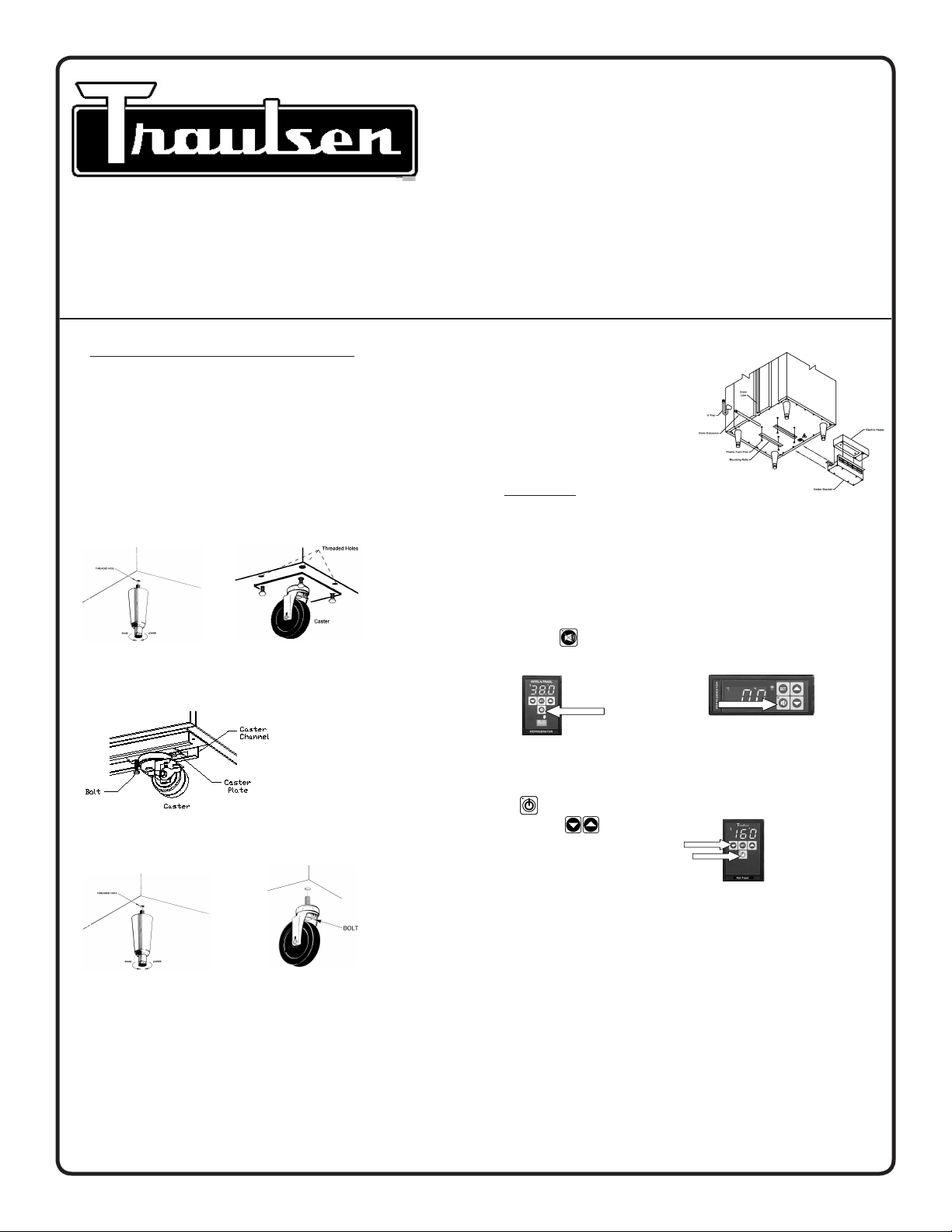
After uncrating the unit, select a level location for final placement. Install
the legs or casters as shown below or, in the case of roll-in and roll-thru
models, these must be sealed to the floor in accordance with local health
codes.
R & A Series/G Series Supports (“Stem” type legs)
TE/TU/TS Series Supports
G Series
Compact Undercounter & Prep-Table
TE Series/TU Series/TS Series
NOTE: Some models (model numbers
beginning with “UR” and single section
dual-temps) require provision of a bottom mounted condensate evaporator.
Follow instructions provided with part,
along with this for installation.
II. Operation:
Most Traulsen equipment is plug and play, such as G Series & most Compacts. However, once power is supplied to the unit, some may require
simple steps to get started using your Traulsen equipment, such as the:
R & A Series/TE Series/TU Series/TS Series Cabinets
Although fully operational the control will flash the cabinet temperature
alternatively with the message ELE LOS (power loss). Press the alarm
cancel button to cancel this message.
R & A Series Control TE/TU/TS Series Control
Compacts Supports (“Stem” type legs & casters)
All models (except undercounters) should be installed to allow at least 12”
of clear space above the unit. In all cases the louvers must be free of any
obstruction which could prevent proper air-flow.
Most units are supplied with a cord and plug, which can simply be
plugged into a dedicated appropriately sized outlet. For those requiring
hard-wiring directly to the power supply, this should be done by only a
qualified electrician.
TR35924 P/N 375-60293-00 (rev. 3-11)
Hot Food Holding Cabinets
Are shipped in the Off position. To begin use, first press the ON/OFF
button , and then adjust to the desired operating temperature using
the UP/DOWN buttons.
Hot Food Control
G Series/Compact Cabinets
Are fully operational and no action is required to start. Please note, most
compacts are equipped with a electromechanical control.
Compact Cabinets (electromechanical)
The temperature is set at the factory but local conditions may necessitate slight adjustment. The temperature control is located in the front
of the evaporator housing. To adjust, turn the adjustment screw with
a screwdriver a small amount at a time; turning clockwise lowers the
temperature. An “OFF” position is fully counterclockwise and interrupts power to the compressor and condenser fan only, not the entire
refrigerator.
Page 2
III. Control Basics:
Customer Access
To adjust any of the control’s operating features, enter the customer access
code. Use the code 0, A, 1 combined with the following: Press the SET
button. The display will read CUS (Customer Access). Press the SET button. The display will show three zeros with the left zero flashing, Press the
SET button. The display will show three zeros with the center zero flashing.
Press the DOWN ARROW key to sequence through F, E, d, C, b, A, 9, 8,
7,…etc. When you reach A press SET. The display will show zero, A, zero
with the right zero flashing. Press the UP ARROW key to sequence through
1, 2, 3, 4, 5, 6, 7, 8, 9, A, b,…etc. When you reach 1 press SET. The
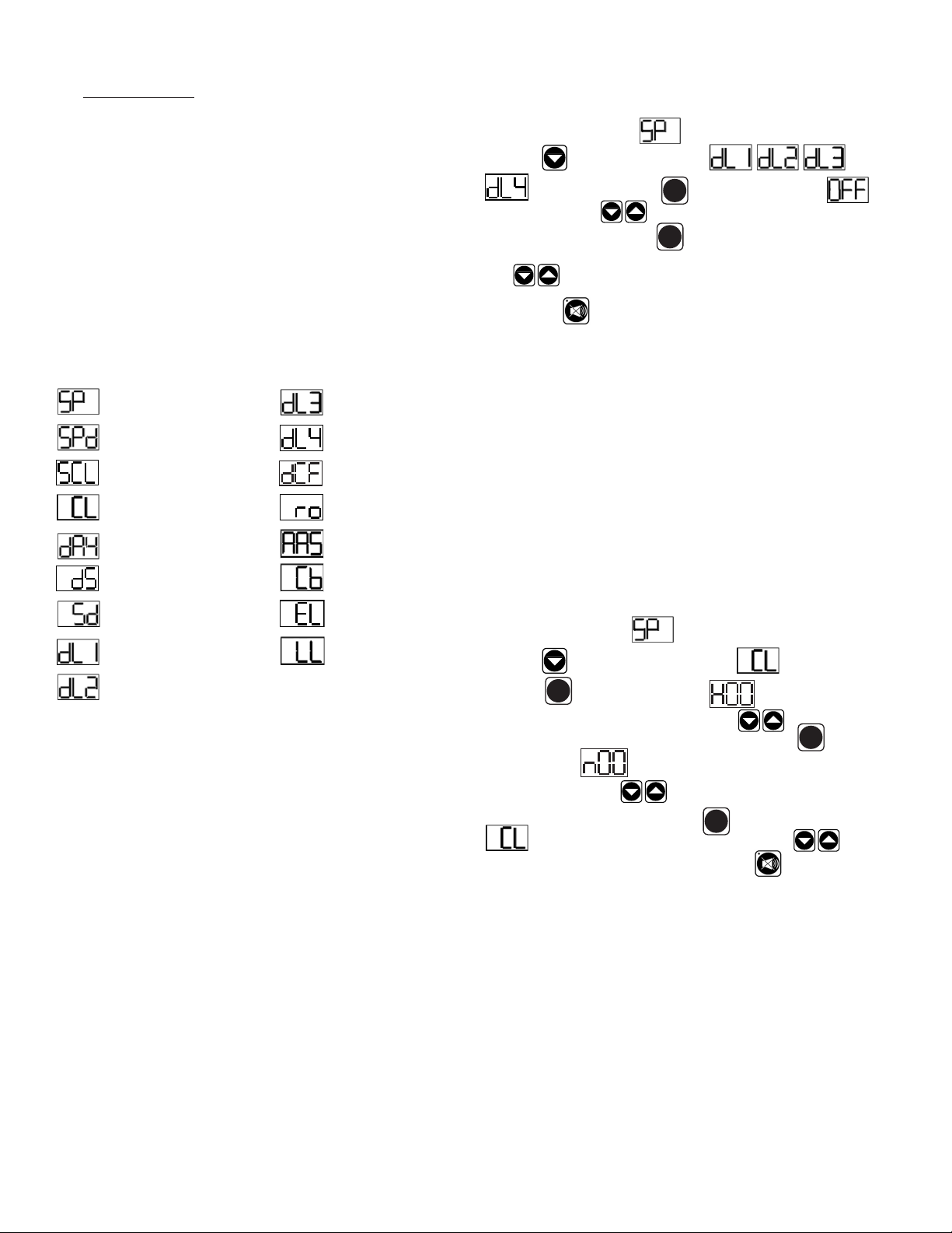
display will read SP (Thermostat Set Point). Press the SET button to view
and again to exit. You are now ready to adjust the control. Listed below
are the available parameters in the order they appear, using the down arrow
key on the controller, you can use either the up or down arrow keys to scroll
through the options.
Thermostat Set Point Defrost Lockout 3
Thermostat Set Point Differential
Defrost Lockout 4
Defrost Lockout Feature (continued)
NOTE: First Enter Customer Access (see section III.)
When the control displays
arrow key
until the control displays or
. Press the set button . The display will show off.
Press the arrow keys
displayed, press the set button
keys
to scroll to the next parameter or press the alarm cancel
Thermostat Set Point, press the down
SET
to set the start time. When the correct time is
SET
. You can press the up or down arrow
button to exit or leave inactive for 30 seconds.
Setting The Clock
The internal time clock must be set in order for the data storage memory to
correctly log events and to allow any defrost lockout to occur at the correct
time of day. If the clock is not set, the control assumes the time is 12 a.m.
at the time power is supplied to the unit. The hours on a 24-hour time clock
read the following way:
Temperature Scale Dew Point Compensation Factor
Time (24-hour clock)
Date (month-day-year) Audible Alarm Style
Daylight Savings Cabinet Air Sensor Temp
Start Manual Defrost
Defrost Lockout 1 Liquid Line Sensor
Defrost Lockout 2
Room Temperature Offset
Evaporator Coil Sensor
Defrost Lockout Feature
Defrost lockouts will allow the you to prevent defrost cycles from occurring
for two hours during a designated time. Up to four can be set for any 24hour period. Each of the lockout parameters covers 6-hours of the 24-hour
clock. Note: The 24-hour clock must be set for this feature to operate at the
correct time of day.
DL1/OFF DL2/OFF DL3/OFF DL4/OFF
020 = 2:00 a.m. 080 = 8:00 a.m. 140 = 2:00 p.m. 200 = 8:00 p.m.
023 = 2:30 a.m. 083 = 8:30 a.m. 143 = 2:30 p.m. 203 = 8:30 p.m.
030 = 3:00 a.m. 090 = 9:00 a.m. 150 = 3:00 p.m. 210 = 9:00 p.m.
033 = 3:30 a.m. 093 = 9:30 a.m. 153 = 3:30 p.m. 213 = 9:30 p.m.
040 = 4:00 a.m. 100 = 10:00 a.m. 160 = 4:00 p.m. 220 = 10:00 p.m.
043 = 4:30 a.m. 103 = 10:30 a.m. 163 = 4:30 p.m. 223 = 10:30 p.m.
050 = 5:00 a.m. 110 = 11:00 a.m. 170 = 5:00 p.m. 230 = 11:00 p.m.
053 = 5:30 a.m. 113 = 11:30 a.m. 173 = 5:30 p.m. 233 = 11:30 p.m.
060 = 6:00 a.m. 120 = 12:00 p.m. 180 = 6:00 p.m. 240* = 12:00 a.m.
063 = 6:30 a.m. 123 = 12:30 p.m. 183 = 6:30 p.m. 243* = 12:30 a.m.
070 = 7:00 a.m. 130 = 1:00 p.m. 190 = 7:00 p.m. 010 = 1:00 a.m.
073 = 7:30 a.m. 133 = 1:30 p.m. 193 = 7:30 p.m. 013 = 1:30 a.m.
080 = 8:00 a.m. 140 = 2:00 p.m. 200 = 8:00 p.m. 020 = 2:00 a.m.
H01 = 1:00 a.m. H07 = 7:00 a.m. H13 = 1:00 p.m. H19 = 7:00 p.m.
H02 = 2:00 a.m. H08 = 8:00 a.m. H14 = 2:00 p.m. H20 = 8:00 p.m.
H03 = 3:00 a.m. H09 = 9:00 a.m. H15 = 3:00 p.m. H21 = 9:00 p.m.
H04 = 4:00 a.m. H10 = 10:00 a.m. H16 = 4:00 p.m. H22 = 10:00 p.m.
H05 = 5:00 a.m. H11 = 11:00 a.m. H17 = 5:00 p.m. H23 = 11:00 p.m.
H06 = 6:00 a.m. H12 = 12:00 p.m. H18 = 6:00 p.m. H24 = 12:00 a.m.
NOTE: First Enter Customer Access (see section III.)
When the control displays
arrow key
Set button
until the control display reads clock. Press the
SET
. The display will show Hours. The right two
Thermostat Set Point, press the down
numbers will be flashing. Use the arrow keys to set the hour.
SET
When the correct hour is displayed, press the Set button
display will show
ing. Use the arrow keys
hour is displayed, press the Set button
minutes. The right two numbers will be flash-
to set the minutes. When the correct
. The display will then read
SET
clock. You can use the up or down arrow keys
next parameter or press the alarm cancel button
. The
to the
to exit or leave
inactive for 30 seconds.
Hot Food Holding Cabinet Operation
Hot Food Holding Cabinets differ from refrigerators and freezers in that they
do not typically operate 24/7, and that there is a much broader range of
safe storage temperatures to choose from (135-180°F). As a result these
are regularly turned ON and OFF. To facilitate this Traulsen includes an ON/
OFF button on their controls. This also includes a convenient Temperature
Recall Feature. Upon being turned on each day, this automatically returns
operation to the last previously set temperature.
-2-
Page 3

Hot Food Holding Cabinet Operation (continued)
Turning the unit OFF/ON: After the temperature has been set, the customer
can continuously turn the unit OFF and then back ON to the same temperature.
To turn the unit on or off press the ON/OFF button
Temperature Adjustment: Press the SET button
button at the same time. The display will flash the current temperature
.
SET
and the UP Arrow
VI. ADJUSTING THE SHELVES:
Shelves Mounted On Pins
First select the desired location and remove the white plastic covers in the
interior back and sides by rotating them counter-clockwise. Remove the
shelf pins by rotating them counter-clockwise. Install the pins in the desired
location by rotating them clockwise. Make sure the pin is securely tightened
down. Do not over tighten. Slide the shelf into its new position, and replace
the white plastic covers into the holes vacated by the shelf pins.
setting or OFF (if the unit is turned off). Use the UP
or DOWN
Arrow buttons to adjust your desired temperature setting (temperature range
0
thru 1800F, and OFF) then press the SET button
is 140
SET
. The display
will go back to reading the cabinet temperature.
Important Alarm Events
Also, some R & A Series models can register alarm events on the control
display such as:
ELE LOS: Indicates that the power supply had been interrupted.
DOR OPN: Indicates that a door has been left open.
HI CAB: Indicates that the cabinet air temperature is too high.
LO CAB: Indicates that the cabinet air temperature is too low.
CLN FIL: Indicates that the condenser coil requires cleaning.
CAB SNR: Indicates cabinet sensor has failed.
COL SNR: Indicates coil sensor has failed.
DIS SNR: Indicates liquid line sensor has failed.
IV. Defrost Cycles:
All Upright Cabinets, defrost cycles will occur every 8 hours for all refrigerators and every 4 hours for all freezers. All TE & TU Series defrost
cycles occur every 2 1/2 hours. All TS Series defrost cycles occur every
3 hours and all Compacts, undercounter and prep table refrigerators, will
occur every 6 hours.
Units equipped with an LED temperature display will indicate when a defrost
cycle is in process.
Shelves Mounted On Clips & Pilasters
Shelves and shelf clips are shipped with the unit. For each shelf, insert
four (4) shelf clips into the pilaster slots at the same height. The shelf
clips have a small projection on top which holds the shelf in position and
prevents it from slipping forward. After installing shelf clips on pilasters,
place shelves on clips.
VII. CLEANING THE CONDENSER:
WARNING: DISCONNECT ELECTRICAL POWER SUPPLY BEFORE
CLEANING ANY PARTS OF THE UNIT.
This is the single most important thing you can do to promote long, efficient
equipment life. For All Upright Cabinets, remove the two bottom screws
securing the louver panel, then pivot this upwards allowing full access to the
front facing condenser. For all TE Series, TU Series & TS Series, place
hands under the louver panel and pull out and up to get louver panel off
bracket of the unit. Contact factory service support for all Compacts.
R & A Series/G Series TE/TU/TS Series
Louver Louver
Screw
Location
V. GENERAL CARE:
WARNING: DISCONNECT ELECTRICAL POWER SUPPLY BEFORE CLEANING ANY PARTS OF THE UNIT.
All Traulsen equipment should be cleaned only with warm water, mild soap
and a soft cloth. Apply with a dampened cloth and wipe in the direction of
the metal grain.
Avoid the use of strong detergents and gritty, abrasive cleaners as they
may tend to mar and scratch the surface. Do not use cleansers containing
chlorine, this may promote metal corrosion.
Care should also be taken to avoid splashing the unit with water, containing
chlorinated cleansers, when mopping the floor around the unit.
For stubborn odor spills, use baking soda and water (mixed to a 1 TBSP
baking soda to 1 pint water ratio).
Vacuum or brush any dirt, lint or dust from the finned condenser coil, around
the compressor and other cooling system parts as indicated. If significant
dirt is clogging the condenser fins, use compressed air to blow this clear.
When finished reverse the louver removal process as instructed above.
Condenser Coil
-3-
Page 4

VIII. TROUBLE SHOOTING:
PROBLEM POSSIBLE SOLUTION
1. Condensing unit fails to start. a. Check if cord & plug has been disconnected.
2. Condensing unit operates for prolonged
periods or continuously.
3. Food Compartment is too warm. a. Check door(s) or drawer(s) and gasket(s) for proper seal.
4. Food Compartment is too cold. a. Check if a large quantity of very cold or frozen food has recently
5. Condensation on exterior surface. a. Check door(s) or drawer(s) alignment & gaskets for proper seal.
6. Compressor hums & does not start. a. Call for service.
a. Are door(s) or drawer(s) closing properly?
b. Dirty condenser or lter. Clean properly.
c. Evaporator coils iced. Needs to defrost.
b. Check if a large quantity of warm food was recently added or the
door was kept open for a long period of time.
c. Microprocessor control setting is too high, readjust.
been added. Allow adequate time for the cabinet to recover its
normal operating temperature.
b. Adjust the microprocessor control to warmer setting, readjust.
b. Condensation on the exterior surface of the unit is perfectly
normal during periods of high humidity.
c. Check perimeter heat setting and increase setting if <100.
IX. CONTACT/WARRANTY INFORMATION:
NOTE: Before making contact, please make sure you have model
and serial number of unit available. Amp plate with information needed
is located on the unit.
Local Authorized Service Agent
1. Log onto www.traulsen.com
2. Select Contact Us/Dealer Directory (top right of screen)
3. Click on Service Directory tab
4. Select state by using the drop down box
5. Select Go
If local service agent is not satisfactory, you may contact Traulsen direct
at (800) 825-8220 or (817) 740-6748 option 3 for Tech Support.
Replacement Parts
To purchase replacement parts for Traulsen and most Hobart refrigeration
units, please contact our Ft. Worth facility by phone at (800) 825-8220
or (817) 740-6748 option 2 for parts.
Warranty
The warranties for your new Traulsen unit may be registered with us by
contacting our Ft. Worth facility directly by phone (800) 825-8220 or (817)
740-6748 option 4 for warranty or you may register on-line.
1. Log onto www.traulsen.com
2. Select Contact Us/Dealer Directory (top right of screen)
3. Select Warranty Registration (lower right of screen)
4. Fill out information requested
5. Select Submit to complete unit warranty registration
Amp Plate
NOTE: You will be required to register for a login name and pass code
to access our on-line information/registration.
Contact Us Direct
Traulsen
4401 Blue Mound Road Fort Worth, TX 76106
Phone: (800) 825-8220 or (817) 740-6748
Parts Fax: (817) 817-740-6748
Tech/Warranty Fax: (817) 740-6757
HOURS OF OPERATION:
Monday thru Friday 7:30 am - 4:30 pm CST
Quality Refrigeration
Traulsen
4401 Blue Moud Road Fort Worth, TX 76106
Phone (800) 825-8220 Fax (817) 740-6757
Website: www.traulsen.com
© 2011 Traulsen - All Rights Reserved
 Loading...