

Trapzilla TZ-160 series, TZ-400-ECA, TZ-400 series, TZ-160-ECA, TZ-600-SSA Installation & Maintenance Instructions Manual
...
A THERMACO® Technology
For additional information on Trapzilla or other Thermaco products,
please visit www.trapzilla.com or call at 1-800-633-4204.
Copyright ©2017 Trapzilla® Thermaco, Inc. • P.O.Box 2548 • Asheboro, NC 27204
Toll Free: (800) 633-4204 • Phone: (336) 629-4651 • Fax: (336) 626-5739
info@thermaco.com • www.trapzilla.com
Installation & Maintenance Instructions
For Trapzilla® Grease Interceptors
Part# MNL-TZ
AFE
*Please consult Thermaco, Inc. for specic models tested,
certied and/or listed by these organizations.
®
Conforms to ASME Standard
ASME A112.14.3-2000
Please consult Thermaco, Inc. for specic models tested,
certied and/or listed by these organizations.
®
©2017 Thermaco, Inc. All rights reserved • Patented/Patents Pending • Specications subject to change without notice
Thermaco, Inc. • 646 Greensboro St. • Asheboro, N. C. 27204-2548 • (336) 629-4651
MNL-TZ 4
A THERMACO® Technology
Trapzilla® Grease Interceptor
Installation and Operations Manual
TZ-160, TZ-400, TZ-600 Models
AFE
MNL-TZ 3
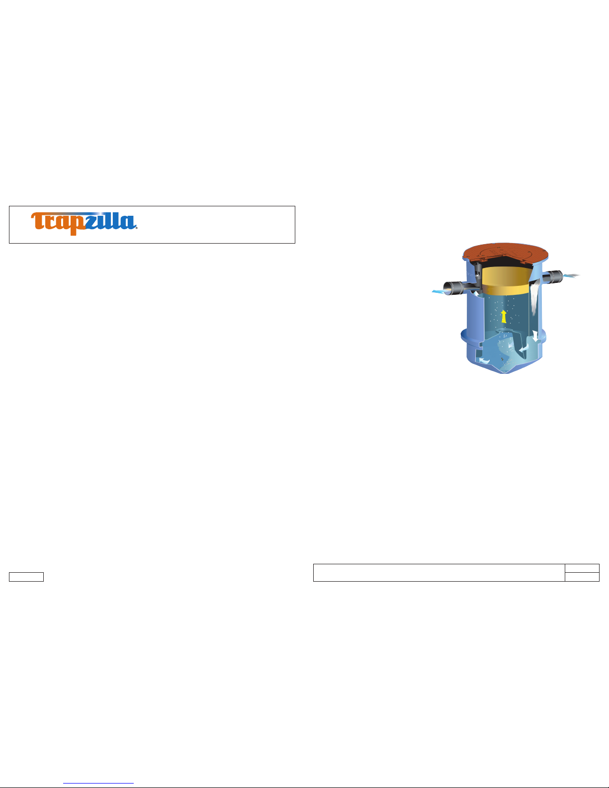
1.0 System Overview
The Thermaco, Inc. Trapzilla® Supercapacity Grease Interceptor collects free-oating grease & oils
contained in kitchen drain water ows. As
most food service facility managers already
know, grease buildup inside a building’s
grease containment system is a major
cause of problems due to exterior drain
line blockages. These problems jeopardize
normal operations as well as create health
and safety hazards within the facility itself.
The proper installation of a Trapzilla®
Supercapacity Grease Interceptor can
reduce or eliminate grease problems and
costly sewer surcharges and nes through
efcient separation and retention of freeoating grease & oils.
The Trapzilla offers patented flat separation
curve technology. This means that the unit does
not lose grease separation efciency as it lls with retained grease. Thus, the Trapzilla stores large quantities
of grease without losing efciency. The unique compact design of the Trapzilla allows for installation into most
facilities. Options are available that enable a Trapzilla unit to be installed on the oor, suspended from the ceiling
or in-ground outside the facility.
Trapzilla units are designed to treat high ows of kitchen drainwater with large grease storage capacity
within a small footprint unit. These units are easy to maneuver into position and just as easy to plumb.
Grease interceptors, grease traps, automatic recovery units, grease removal devices and other similar
plumbing devices receiving kitchen ows from sinks, oor drains, woks and other food bearing sources
may generate odors. There are many factors inuencing odor evolution and dissemination. These include
room ventilation, kitchen menu, ambient temperatures, ware washing practices, grease/oil input, daily
input uid volume, sanitizers, installation plumbing design and product maintenance/upkeep. Odors are
usually prevented by good area ventilation, frequent uid inputs, good product maintenance practices
and proper product installation. Additional steps, including aeration, chlorination, pH control, improved
area ventilation and additional maintenance may be needed at some sites.
Contents
1.0 System Overview.................................................................................................................................. 4
2.0 Models and Options.............................................................................................................................. 5
2.1 In-Ground Models .......................................................................................................................... 5
2.2 Above-Ground Models ................................................................................................................... 6
2.3 Basic Models ................................................................................................................................. 7
2.4 Options (Some options must be purchased separately) ................................................................. 8
3.0 Plumbing Installation ............................................................................................................................ 9
3.1 Plumbing Considerations Prior to Installation ................................................................................ 9
3.1.1 Locating the Unit .................................................................................................................... 9
3.1.2 Inlet/Outlet Piping .................................................................................................................. 9
3.1.3 Flow Controls ......................................................................................................................... 9
3.1.4 Venting the Outlet .................................................................................................................. 9
3.1.5 For High Head Height Applications Over Six (6) Feet (1.95 m) ............................................. 9
3.2 Vessel Vent Connection ................................................................................................................. 10
3.3 Plumbing Congurations ................................................................................................................ 11
3.3.1 Installing One Trapzilla Unit ................................................................................................... 11
3.3.2 Installing Multiple Trapzilla Units in Parallel ........................................................................... 12
3.3.3 Installing Two Trapzilla GI’s in Series or One Solids Separator and One Trapzilla ............... 13
3.3.4 One Solids Separator and Two Trapzilla Units ...................................................................... 14
3.3.5 Two Solids Separators and Two Trapzilla Units ..................................................................... 15
4.0 Above-Ground Installation .................................................................................................................... 16
4.1 Components for Above-Ground Installations .................................................................................. 16
5.0 In-Ground Installation ...........................................................................................................................18
5.1 Plumbing Instructions for Single Trapzilla Installed In-Ground ....................................................... 18
5.2 Plumbing Instructions for Multiple Trapzilla Units Installed In-Ground ........................................... 19
5.3 Trimming and Setting the ECA-TZ-18 Single-Piece Extension Collar ............................................ 20
5.4 Concrete Calculations for TZ Models/Components ........................................................................ 22
6.0 Hanging Installation .............................................................................................................................. 23
©2017 Thermaco, Inc. All rights reserved • Patented/Patents Pending • Specications subject to change without notice
Thermaco, Inc. • 646 Greensboro St. • Asheboro, N. C. 27204-2548 • (336) 629-4651
MNL-TZ 6
A THERMACO® Technology
Trapzilla® Grease Interceptor
Installation and Operations Manual
TZ-160, TZ-400, TZ-600 Models
AFE
MNL-TZ 5
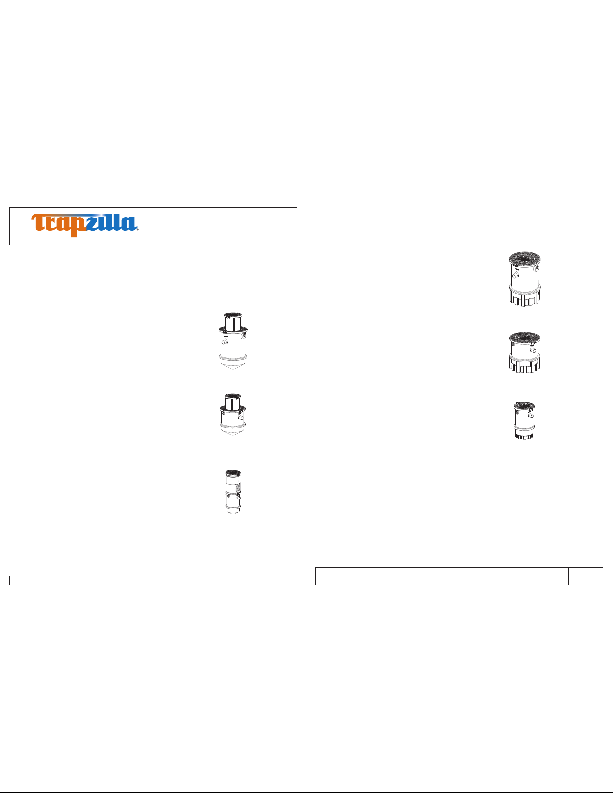
TZ-600-ECA
1
2
3
635 pounds of grease storage, ASME rated at 75 gpm, while
hydromechanically capable of ow rates of up to 150 gpm.
Equipped with 4” inlet/outlet, 2” vessel vent connection, and
4” Low-Head Flow Control Accessory to limit ow to 75 gpm.
Comes with: 18” tall Extension Collar Adapter Lid
Assembly with 22” diameter lid.
TZ-400-ECA
405 pounds of grease storage, ASME rated at 75 gpm.
Equipped with 4” inlet/outlet, 2” vessel vent connection, and
4” Low-Head Flow Control Accessory to limit ow to 75 gpm.
Comes with: 18” tall Extension Collar Adapter Lid
Assembly with 22” diameter lid.
1
2
3
TZ-160-ECA
167 pounds of grease storage, ASME rated at 35 gpm.
Equipped with 3” inlet/outlet, 2” vessel vent connection, and
3” Low-Head Flow Control Accessory to limit ow to 35 gpm.
Comes with: 22” diameter lid and 29” Telescoping
Extension Collar.
1
2
3
*Model available with 6” Inlet/Outlet, add sufx -6 to model.
TZ-600-SSA
1
2
3
4
635 pounds of grease storage, ASME rated at 75 gpm, while
hydromechanically capable of ow rates of up to 150 gpm.
Equipped with 4” inlet/outlet, 2” vessel vent connection, and
4” Low-Head Flow Control Accessory to limit ow to 75 gpm.
Comes with: Standard Adapter Top Cover with 22”
diameter lid, and Support Stand SSOP-400/600.
TZ-400-SSA
405 pounds of grease storage, ASME rated at 75 gpm.
Equipped with 4” inlet/outlet, 2” vessel vent connection, and
4” Low-Head Flow Control Accessory to limit ow to 75 gpm.
Comes with: Standard Adapter Lid Ring with 22” diameter
lid, and Support Stand SSOP-400/600.
1
2
3
4
TZ-160-SSA
167 pounds of grease storage, ASME rated at 35 gpm.
Equipped with 3” inlet/outlet, 2” vessel vent connection, and
3” Low-Head Flow Control Accessory to limit ow to 35 gpm.
Comes with: 22” diameter lid and Support Stand SSA-160.
1
2
*Model available with 6” Inlet/Outlet, add sufx -6 to model.
2.0 Models and Options
Thermaco offers different models and options specically designed to assist the owner/installer meet
site conditions while complying with local pretreatment and plumbing code.
2.1 In-Ground Models
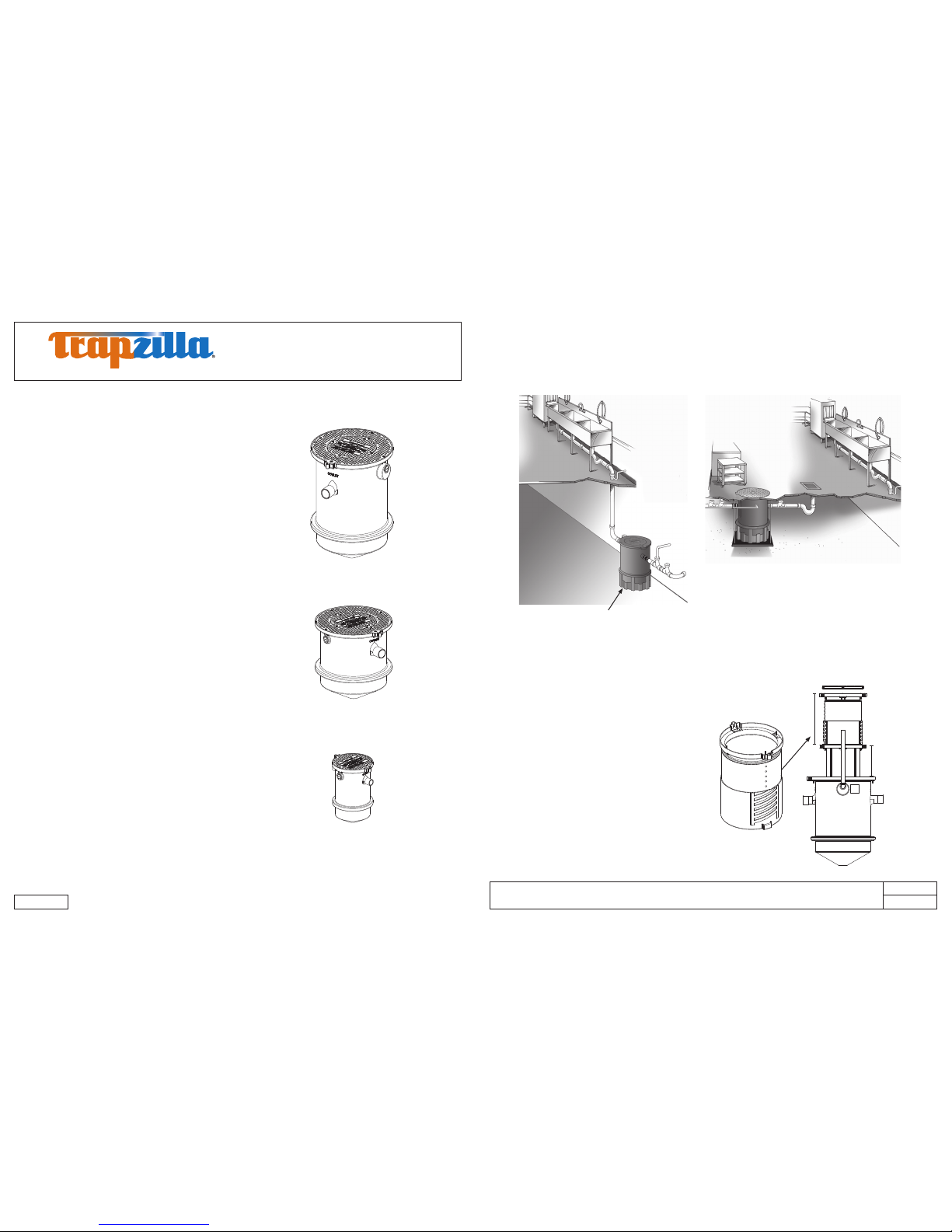
2.2 Above-Ground Models
©2017 Thermaco, Inc. All rights reserved • Patented/Patents Pending • Specications subject to change without notice
Thermaco, Inc. • 646 Greensboro St. • Asheboro, N. C. 27204-2548 • (336) 629-4651
MNL-TZ 8
A THERMACO® Technology
Trapzilla® Grease Interceptor
Installation and Operations Manual
TZ-160, TZ-400, TZ-600 Models
AFE
MNL-TZ 7
TZ-600
TZ-400
TZ-160
1
2
3
4
635 pounds of grease storage, ASME rated at 75 gpm,
while hydromechanically capable of ow rates of up to
150 gpm. Equipped with 4” inlet/outlet, 2” vessel vent
connection, and 4” Low-Head Flow Control Accessory to
limit ow to 75 gpm.
Comes with: Standard Adapter Lid Ring with 22”
diameter lid.
405 pounds of grease storage, ASME rated at 75 gpm.
Equipped with 4” inlet/outlet, 2” vessel vent connection,
and 4” Low-Head Flow Control Accessory to limit ow to
75 gpm.
Comes with: Standard Adapter Lid Ring with 22”
diameter lid.
167 pounds of grease storage, ASME rated at 35 gpm.
Equipped with 3” inlet/outlet, 2” vessel vent connection,
and 3” Low-Head Flow Control Accessory to limit ow to
35 gpm.
Comes with: 22” diameter lid.
1
2
3
4
1
2
*Model available with 6” Inlet/Outlet, add sufx -6 to model.
FTCA-36
Fabricated Top Cover Assembly with 36” diameter
for additional traction in high foot-trafc areas and 4”
Brass cleanout port.
FTCA-22 (not shown)
22” diameter cover available for In-Ground installations.
SSOP-400/600
Support Stand for TZ-400 and TZ-600 models
Allows unit to be installed directly on the oor in a
basement or mechanical room.
*Included with -SSA Models
ECA-TZ-29 (in blue) for Trapzilla
Models
These eld-modiable extension collars
available to provide additional depth for
existing kitchen drainage piping.
-ECA Models ship with built-in
0-18” extension collar.
ECA-TZ-29 adds 0-29” depth to -ECA
Models or 4-29” to Basic Models.
1
2
3
1
2
ECALA-TZ-18
ECA-TZ-29
2.3 Basic Models
2.4 Options (Some options must be purchased separately)
 Loading...