

Trapeze Software Group RAN45728, RAN49110, RAN48790 Installation Manual

Hardware Installation Guide
Ranger 7-RNGR-04X
Ver 5.4
Copyright © 2008 Mentor Engineering Inc. All rights reserved.

Table of ConTenTs
Safety & After-Market Equipment ........................................4
Qualified Installer ...............................................................5
Introduction .......................................................................7
Cautions .......................................................................8
Before You Begin ................................................................8
Parts List ...........................................................................9
Supplied .......................................................................10
Supplied (Optional) ........................................................11
Not Supplied .................................................................11
Mounting Locations ............................................................12
Placement .....................................................................12
Ranger Mounting Examples .................................................13
Examples of Suitable Mounting Locations .........................13
Installing The Ranger Cover Plate ........................................14
Wiring - Ranger Back View .................................................17
Connection Points ..............................................................19
1) Splicing ...................................................................19
2) Power ......................................................................19
3) Ground ....................................................................19
4) Switched Ignition Power ............................................19
5) VSS (Vehicle Speed Sensor for Odometer Pulses) .........21
6) Emergency Switch (optional) ......................................22
Cabling ..............................................................................23
1) Routing....................................................................23
2) Strain Relief .............................................................23
3) Labeling ..................................................................24
4) Connection Types ......................................................24
5) Wire Types ...............................................................25
6) Electrical Measurements ............................................25
Antennas ...........................................................................26
2

Table of ConTenTs
1) Internal Antennas .....................................................26
2) External Antennas .....................................................26
3) Cable Routing...........................................................27
4) Connectors ...............................................................28
Ranger Specs 7-RNGR-04X...............................................29
General Description ........................................................29
Standard Features ..........................................................29
Compliance and Testing ..................................................30
Optional Features ...........................................................30
Key Specifications ..........................................................30
Appendix A - Conformity .....................................................33
1) FCC Class B Part 15 .................................................33
2) IEC 60950 3rd Edition (2000) Safety of Information Tech-
nology Equipment .....................................................35
3) ISO 7637-1 Load Dump Transient ..............................35
4) MIL STD 810F: General Vibration ...............................35
5) MIL STD 810F: Shock Test ........................................35
6) IEC 60529 - IP54 ....................................................35
Appendix B - RF Radiation Specs ........................................36
RF Exposure ..................................................................36
Appendix C - Approvals .......................................................37
1) CDMA/EVDO ............................................................37
2) GSM/HSDPA ............................................................37
3) WIFI/Bluetooth Only ..................................................37
3

WARNING
FAILURE TO INSTALL THE EQUIPMENT
AS RECOMMENDED COULD CAUSE OR
CONTRIBUTE TO AN ACCIDENT AND RESULT
IN DAMAGE TO PROPERTY OR PERSONS.
safeTy & afTer-MarkeT equipMenT
The use of after-market equipment in motor vehicles can
compromise a vehicle’s safety-related design characteristics,
including but not limited to:
• Airbags, including but not limited to potential obstruction of air-
bag deployment;
• Passenger compartment, including but not limited to potential for
ergonomic problems, physical obstacles, etc.; and
• Trunk/gas tank protection, including but not limited to the poten-
tial for trunk-mounted equipment to exacerbate tank vulnerability
in a rear collision.
4

WARNING
This product is to be installed by
qualified installation personnel only.
Incorrect installation may result in FIRE
or contribute to an ACCIDENT
qualified insTaller
This product is to be installed by qualified installation personnel only.
The installer must be trained in industry best practices for this type of
installation. The training would include but not be limited to:
1. The appropriate methods for installing cables such that:
• The operation of the vehicle is not interfered with.
• The installation process does not damage or interfere with other
vehicle components and/or systems.
• Wiring is kept clear of sharp objects, sources of heat and any
other hazard that could damage the cable or wire.
• Wiring is secured such that it does not cause damage to other equip-
ment, itself, or interfere with the operation of other systems and
devices.
• Wiring through bulkheads is performed such that wiring does not
chafe, and a seal is maintained between compartments.
• Appropriate and industry standard fasteners, splices, connectors
and ties are used for the vehicle environment.
• Appropriate slack is in place to prevent straining of the wire, cable
or connectors.
• Any other issue that could affect the integrity of the wiring or the
safe operation of the vehicle is addressed appropriately.
5

qualified insTaller
2. The appropriate methods for mounting equipment in vehicles such
that:
• The safe operation of the vehicle is not interfered with.
• The equipment is attached to the vehicle as securely as possible to
minimize the risk of the equipment breaking free in an accident situation.
• The installed device does not interfere with the deployment of air
bags.
• The installed device does not obscure displays or interfere with the
ability of the driver to operate other vehicle systems and components.
• The installation process does not damage other vehicle systems or
components.
• Compartments remain sealed against the elements.
3. The correct use and operation of the required tools.
Further:
• The installer must have the ability to read, understand and follow
the instructions in the installation manual.
• The installer must be equipped with the correct tools for perform-
ing each installation operation.
The Customer must ensure that the installation of all equipment provided for this project is safe, used for its intended purpose, and is in
continual accordance with all applicable codes, rules, regulations and
guidelines provided by motor vehicle and equipment manufacturers, as
well as any state, local or jurisdictional bodies.
6

inTroduCTion
Mentor Ranger® v4.0 is a Windows CE fixed-mount computer
for two-way wireless communication, electronic dispatching, invehicle navigation, and more.
This Ranger Installation guide includes directions for successfully
installing and interfacing a Ranger into a vehicle. Specific wiring
and installation procedures may change from customer to
customer and should be discussed prior to installation. If any
questions remain after reading this guide,please contact Mentor
Engineering, (403) 777-3760 ext. 3, for more information.
4.0
7

before you begin
CAUTIONS
a) Carefully read the Installation Guide before installing this
product. If anything is unclear please contact Mentor
Engineering for support.
b) Ensure that the NEGATIVE battery connection is disconnect-
ed before beginning work.
NOTE: Some components may lose short-term memory (i.e.
engine or transmission adaptive parameters, and radio presets) after a protracted time without battery power.
c) Ranger should be serviced by qualified, trained personnel
only. Attempting to remove the cover or disassemble the
device could expose you to dangerous high voltage points.
d) Only use a damp cloth for cleaning. Never use any type of
liquid/aerosol cleaner or any type of organic solvent to clean
this product.
e) Do not attempt to install or operate a damaged device. If the
unit has been exposed to excessive amounts of water; shows
evidence of physical damage; or is not operating properly;
unplug it from the power source and contact qualified service
personnel.
f) Use of thread-locking compounds such as Loctite may cause
serious damage to plastic enclosures. Many thread-locking
compounds are not compatible with thermoplastics and can
lead to stress cracking. This will require the unit to be returned to replace the ABS enclosures.
ENSURE THAT YOU HAVE ALL OF THE ITEMS LISTED IN
THE PARTS LIST
8
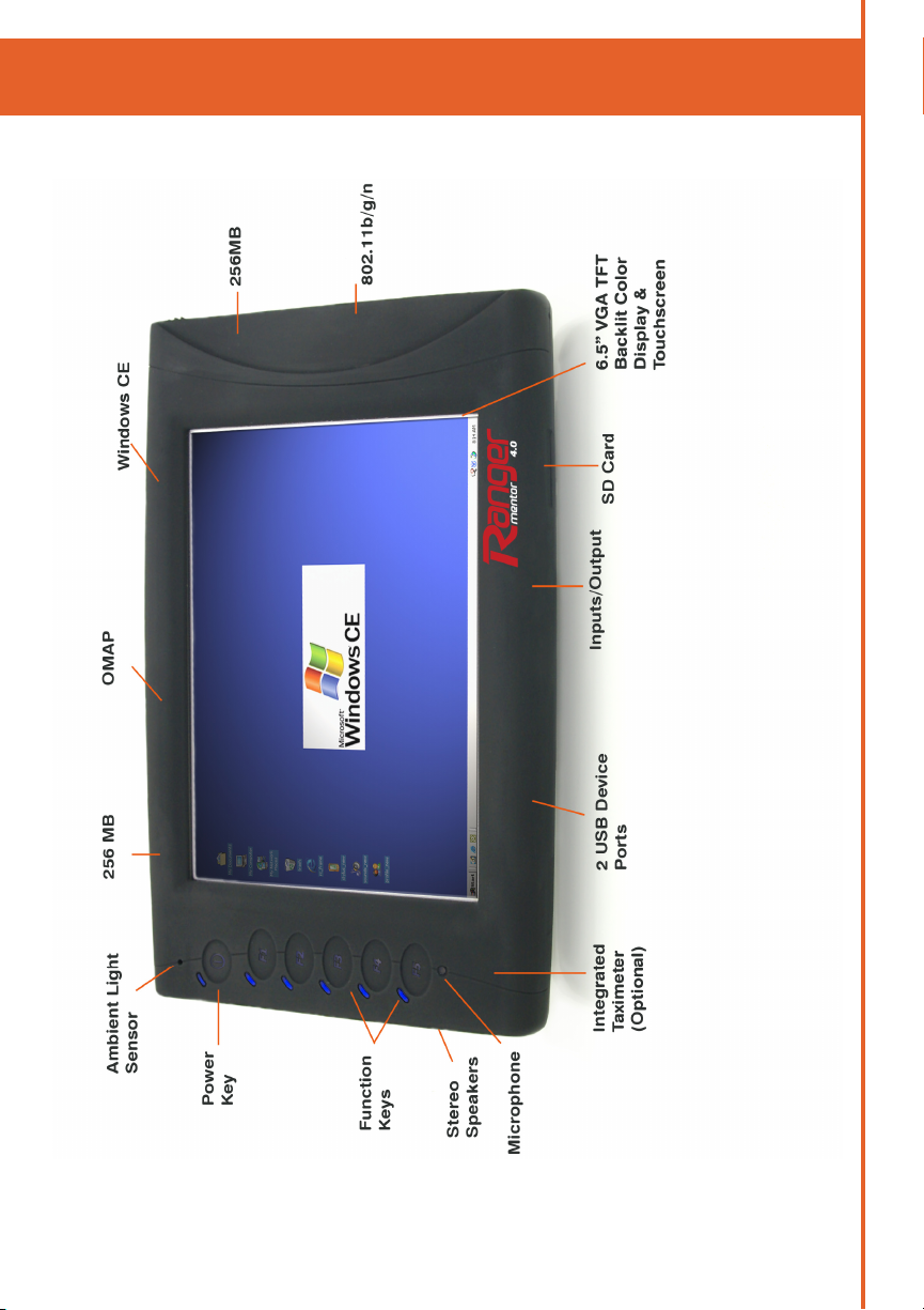
ranger overview
9
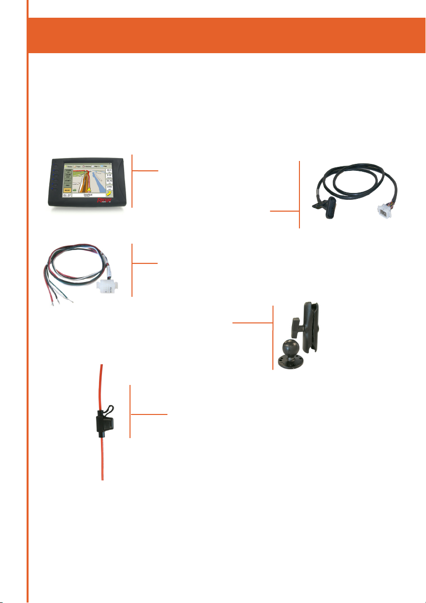
parTs lisT
Please verify that you have everything that you need to
complete the Ranger installation. NOTE: Not all parts
are provided by Mentor.
SUPPLIED
• Ranger
• Ranger Interface Cable
4-CAS-CGRDMMLX18-31
• Ranger Power Pigtail
• Ranger Mount
10
• In-line Cable Fuse(s)

parTs lisT
SUPPLIED (OPTIONAL)
• Emergency switch
NOT SUPPLIED
• Zip Ties
• Glued Heat Shrink
• Tools as Required
• Grommets
• Loom
• Fasteners
11

MounTing loCaTions
PLACEMENT
1) Ensure that the driver’s view of the road will not be
impacted.
2) Ensure that the equipment will not be in the path of any
active airbags.
3) Ensure that the driver will still have access to all controls on
the dash.
4) Ensure that the driver has a clear view of the terminal from
the seated driving position.
5) Ensure that the terminal is within easy reach of the driver
from the seated driving position.
6) Ensure that the mounting location is a solid surface.
Locations that allow even small amounts of initial movement
will loosen over time.
12
7) Before drilling any holes or using screws, check for vehicle
wiring under the carpet or behind the instrument panel which
could be pinched, cut or otherwise damaged.
8) If mounting through the floor, put body sealer over the
underbody projections. Stamped acorn nuts, filled with
sealer, are available at most body shops for this purpose.
This will keep moisture out of the carpet and insulation and
will forestall rust in this area.
9) If mounting under the instrument panel, be sure that there is
no interference with proper operation of the foot controls.
10) Inquire if the vehicle will be cleaned with a high pressure
water wand. If so, ensure that all equipment is installed
somewhere that will be protected from this type of cleaning.
 Loading...