

Page 1

Hardware Installation
Guide
Mobile Data Computer (Version 3&4)
Page 2

Page 3

TABLE OF CONTENTS
MDC V3&4HardwareInstallationGuide R07.doc
January 24, 2005
Page 1 of 15
Introduction ....................................................................................................................................................2
1 FCC Compliance Statement (USA).....................................................................................................2
2 What You Need...................................................................................................................................2
Installation......................................................................................................................................................2
1 General ...............................................................................................................................................2
2 MDC Mounting Bracket .......................................................................................................................3
3 MDC Placement ..................................................................................................................................3
4 MDC Connections ...............................................................................................................................3
5 Communications Device .....................................................................................................................5
6 Antenna Installation ............................................................................................................................5
7 Installing Roof Top Antennas..............................................................................................................5
8 General Antenna Guidelines...............................................................................................................6
9 RF Radiation Specifications................................................................................................................7
10 SAR and MPE Limits .......................................................................................................................7
11 Labelling ..........................................................................................................................................7
Basic Operation and Configuration................................................................................................................8
1 Turning the MDC On ...........................................................................................................................8
2 Adjusting the Backlight........................................................................................................................9
3 Accessing the MDC Maintenance Menus ...........................................................................................9
4 Setting the MDC Time and Date ........................................................................................................9
5 Adjusting the LCD Contrast.................................................................................................................9
6 Setting the MDC ID ...........................................................................................................................10
7 Setting Communications Parameters................................................................................................10
Configuring and Testing in the Vehicle ........................................................................................................10
1 Setting the DSP Gain Level (Conventional Radio Systems Only).....................................................10
2 Setting the MDC ID ...........................................................................................................................13
3 Testing the Communications.............................................................................................................13
Technical Data.............................................................................................................................................15
2 Temperature range ...........................................................................................................................15
Suite 230, 2891 Sunridge Way NE, Calgary Alberta, T1Y 7K7
♦
Phone: (403) 777-3760
♦
Fax: (403) 777-3769
Page 4

MDC V3&4HardwareInstallationGuide R07.doc
January 24, 2005
Page 2 of 15
INTRODUCTION
This document provides instructions and guidelines that should be followed for the successful
installation of Mentor Engineering’s Mobile Data Computer (MDC).
1 FCC Compliance Statement (USA)
1.1 FCC Class A Part 15
This device complies with Part 15 of FCC Rules. Operation is subject to the following two
conditions:
a) This device may not cause harmful interference
b) This device must accept any interference received, including interference that may
cause undesired operation.
NOTE: This equipment has been tested and found to comply with the limits for a Class A digital
device, pursuant to Part 15 of the FCC Rules. These limits are designed to provide reasonable
protection against harmful interference when the equipment is operated in a commercial
environment. This equipment generates, uses, and can radiate radio frequency energy and, if not
installed and used in accordance with the instruction manual, may cause harmful interference to
radio communications. Operation of this equipment in a residential area is likely to cause harmful
interference in which case the user will be required to correct the interference at their own
expense.
2 What You Need
For a typical installation in a vehicle, you will need the following:
• MDC
• MDC installation cables (vehicle/power cable and communications adapter cable)
• Mounting bracket
• Cable tie-downs
To assist with the installation, it is often necessary to have the following available:
• PC Laptop
• MDC programming cable
• Multimeter
• Radio service monitor (for systems using mobile radios for communications)
• Radio service monitor (for systems using mobile radios for communications)
INSTALLATION
1 General
The MDCs are shipped pre-programmed with the appropriate communications and application
software. In some cases, however, it is necessary to re-program the units with updated files prior
to installing them. Please refer to the MDC Programming application note for details on reprogramming the units.
Suite 230, 2891 Sunridge Way NE, Calgary Alberta, T1Y 7K7
♦
Phone: (403) 777-3760
♦
Fax: (403) 777-3769
Page 5

MDC V3&4HardwareInstallationGuide R07.doc
January 24, 2005
2 MDC Mounting Bracket
The type of MDC mounting bracket will vary depending on the type of vehicle that the MDC is
being installed in. It will also depend on whether or not an Express QWERTY keyboard is to be
mounted with the MDC. The mounting brackets may be ordered through Mentor, or through a third
party supplier. The following information provides the details necessary for ordering a mounting
bracket along with an adapter plate for the MDC.
Page 3 of 15
Figure 1 Mounting Bracket Adapter Plate
• MDC Mounting screws: 3/8” (10mm) #8 thumb screws
• Adapter Plate Material: 1/8” (3.2mm) aluminum
3 MDC Placement
The placement of the MDC should be carefully considered. It is important that the unit is mounted
so that the driver of the vehicle can easily view and operate the MDC. Attention should be given to
the placement to make sure the MDC does not interfere with regular driving functions. To avoid
damage due to overheating, the MDC should not be mounted where it will be in direct sunlight.
4 MDC Connections
The interface points available on the MDC are grouped on six separate connectors according to
their function.
Suite 230, 2891 Sunridge Way NE, Calgary Alberta, T1Y 7K7
♦
Phone: (403) 777-3760
♦
Fax: (403) 777-3769
Page 6
MDC V3&4HardwareInstallationGuide R07.doc
January 24, 2005
Page 4 of 15
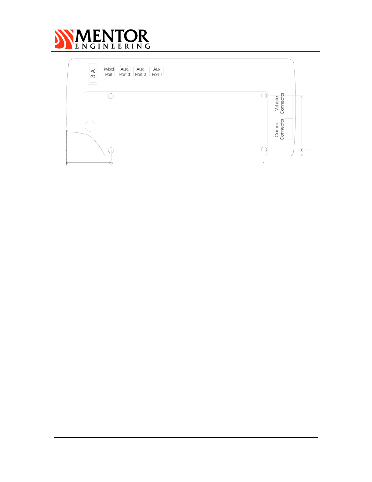
Figure 2 MDC Rear View – MDC Connectors
4.1 Connector Summary
a) Vehicle connector:
MDC power, general use I/O, odometer input and RS485 interface.
b) Communications connector:
General use I/O, covert microphone, internal modem to mobile radio connection
points and an RS232 interface for external data modems.
c) Auxilliary port 1:
RS232 serial interface port used for MDC programming and for connection to
external peripheral devices.
d) Auxilliary port 2:
RS232 serial interface port for connection to external peripheral devices.
e) Auxilliary port 3:
RS232 serial interface port for connection to external peripheral devices.
f) Keyboard port:
Interface port for connection to the Express Mini QWERTY keyboard.
In the most basic MDC installation, only the vehicle and communications connectors will to be
required.
4.2 Communications Interface
The installation cable provided will bring the appropriate interface pins from the
communications connector to an appropriate adapter for the communications device. Details
for specific interfaces are available as application notes from Mentor Engineering, Inc.
4.3 Peripherals Interface
Details regarding the cabling interface for external MDC peripheral devices, odometers, and
additional I/O are available as application notes specific to these functions. These notes are
provided as required by Mentor Engineering, Inc.
4.4 MDC Cables
In general, there will be one cable from the MDC connected to power (see Power Connections
section) and one cable connected to the communications device (radio, modem, etc.). It is
Suite 230, 2891 Sunridge Way NE, Calgary Alberta, T1Y 7K7
♦
Phone: (403) 777-3760
♦
Fax: (403) 777-3769
Page 7

MDC V3&4HardwareInstallationGuide R07.doc
January 24, 2005
Page 5 of 15
common practice to route the cabling through the vehicle so it is not visible to the driver and is
more protected from the environment. Mentor Engineering recommends that this practice be
followed in installations.
In some installations that use GPS, there will also be a GPS antenna that will have to be
mounted on the roof or the trunk of the vehicle and connected to the MDC via the GPS
connector (located at the rear of the MDC underneath the fuse). Note: Mentor strongly
recommends mounting the GPS antenna in the center of the roof for maximum sky view.
4.5 Power Connections
The MDC receives power via the vehicle connector. The installation cable that is provided for
the vehicle connector will have pigtails for connection to power and ground.
Refer to the cabling diagram provided by your Mentor Systems Engineer before making any
power connections. Normally, the RED lead will indicate POWER and the BLACK lead will
indicate GROUND.
The MDC power leads should be crimped onto the power leads at the power input to the
communications device. Installing the power leads in this way will avoid the possibility of the
ground potential at the MDC differing from the ground potential of the communications device
(due to current draw during a transmit cycle).
If the MDC is connected to switched ignition power the unit’s manifest will be lost every time
the engine is turned off. In some systems, the MDC will be connected to ignition power and
will be powered on and off automatically. If the ignition is off the MDC can be powered using
the power switch.
The MDC has a 3-amp fuse on its power input. The fuse is easily accessible via the back of
the unit if it needs to be replaced (port 3A in Figure 2). Note, however, that a blown fuse will
often indicate that there is either a problem with a connection to the MDC or with the MDC
itself. Check all connections before replacing the fuse.
Please refer to the Technical Data section of this manual for details on the voltage and current
requirements of the MDC.
5 Communications Device
There will also be a communications device that will have to be installed in the vehicle. In radio
systems, this will be a mobile radio with its accompanying antenna. If a data system such as
CDPD, DataTAC, iDEN, EDACS or Mobitex is being used, then the communications device will be
a modem (which may be internal in the MDC). The size and location of the communications device
should be taken into account during the installation process to ensure that there is enough space
to mount and install all components of the system in the vehicle.
6 Antenna Installation
Among all installation variables, antenna location has the greatest impact on the performance of
the radio modem. Mentor Engineering recommends using a roof top antenna installed in the center
of the vehicle roof for best coverage and to meet SAF/MPE radiation specifications.(See Following
section: RF Radiation Specifications)
7 Installing Roof Top Antennas
Suite 230, 2891 Sunridge Way NE, Calgary Alberta, T1Y 7K7
♦
Phone: (403) 777-3760
♦
Fax: (403) 777-3769
Page 8

MDC V3&4HardwareInstallationGuide R07.doc
January 24, 2005
Page 6 of 15
These antennas are permanently mounted to the vehicle through a 3/4-inch hole in the roof. Roof
top antennas require a ground plane to achieve maximum gain. To be effective, the ground plane
should have a radius of 6 inches or more. These antennas are available in different gain radiation
patterns. The most common is the 3dB gain variety. A typical 3dB gain antenna is shown below in
Figure 3. For CDPD systems Novatel recommends the use of a Half-Wave Dipole antenna with a
50-ohm nominal impedance. The VSWR should be 1.5:1 nominal with a maximum of 2.0:1. They
assume a 1.2 dB antenna gain. They also specify the module is limited to operate with an antenna
with maximum of 2.15 dBi nominal gain or not to exceed 1.5 Watts ERP for any type of remotely
mounted outdoor external antenna.
Figure 3 3dB Gain Antenna
During the installation, never use a drill bit or hole saw. First, drill a pilot hole. Then, use a hole
cutting punch to make the 3/4-inch hole. This prevents rough edges in the roof of the car that could
result in water leaks. A silicon sealant can also be used, but avoid unnecessary contact with the
vehicle's paint. Because this type of antenna cannot be moved, careful attention to aesthetics and
location are critical. Figure 4 shows the preferred location of the 3dB rooftop antenna.
Figure 4 Location of Roof Mount Antenna
8 General Antenna Guidelines
• Position the antenna as high as possible on the body of the vehicle.
Suite 230, 2891 Sunridge Way NE, Calgary Alberta, T1Y 7K7
♦
Phone: (403) 777-3760
♦
Fax: (403) 777-3769
Page 9

• Keep the RF cable as short as possible. Cut the excess cable during an installation. Do
not wrap it up. Excess cable adds unnecessary loss to the transmitted power.
• Ensure the antenna is in a vertical position during operation.
• Use proper RF connectors. The preferred type of connector is a SMA connector. (See
the “SMA Connector Assembly” section above.)
• Avoid sharp bends and moving objects in the coaxial cable path.
• Position the antenna away from fuel caps.
• Position the antenna on the opposite side of the vehicle, away from the vehicle's AM/FM
radio antenna.
• Follow the antenna manufacturer's guidelines exactly when installing antennas.
• Do not substitute any antenna for the one supplied by the manufacturer. You may be
exposing person(s) to harmful radiation. Contact the supplier or manufacturer for further
instruction
9 RF Radiation Specifications
9.1 FCC Radio Frequency Exposure Rules
Based on FCC rules 2.1091 and 2.1093 and FCC Guidelines for Human Exposure to Radio
Frequency Electromagnetic Fields, OET Bulletin 65 and its Supplement C, all integrations of
the MobiConnect 902 unit are subject to routine environmental evaluation for radio-frequency
(RF) exposure prior to equipment authorization or use.
MDC V3&4HardwareInstallationGuide R07.doc
January 24, 2005
Page 7 of 15
For mobile devices, defined as a transmitting device designed to be generally used such that
a separation distance of at least 20 cm is maintained between the body of the user and the
transmitting radiated structure, the human exposure to RF radiation can be evaluated in terms
of Maximum Permissible Exposure (MPE) limits for field strength or power density in mW /cm2.
9.2 How to Comply With FCC SAR/MPE Guidelines
In order to comply with FCC SAR/MPE Guidelines the antenna must be placed a minimum of
20 cm from the vehicles edge. To accomplish this, and to ensure optimum antenna
performance Mentor Engineering recommends that antenna be installed in the center of the
vehicle rooftop.
WARNING: The user should be instructed to maintain the minimum distance from the
antenna.
10 SAR and MPE Limits
SAR limits for General Population/Uncontrolled exposure is 1.6W/kg for partial body exposure,
averaged over 1 g of tissue and 4 W/kg for hands, wrists and feet averaged over 10 g of tissue.
The limits for Occupational/Controlled exposure are more relaxed, i.e., 8 W/kg for partial body and
20 W/kg for hands, wrists and feet. The 1.6 W/kg limit applies for most users of the MobiConnect.
The limit for MPE is 0.6mW/cm2 at 900 MHz.
RF exposure distance is based on normal operating proximity to the user’s or nearby persons’
body. This distance is measured from any part of a radiating structure, generally the antenna, to
the closest part of the body.
11 Labelling
Suite 230, 2891 Sunridge Way NE, Calgary Alberta, T1Y 7K7
♦
Phone: (403) 777-3760
♦
Fax: (403) 777-3769
Page 10

MDC V3&4HardwareInstallationGuide R07.doc
January 24, 2005
Page 8 of 15
If the antenna is installed at least 20 cm from the vehicle’s edge no warning label is required.
If the antenna is not at least 20 cm from any vehicle edge, an additional RF radiation hazard label
that warns the user or nearby persons to keep away from the antenna by the specified distance is
required. This is because the minimum separation distance of the final device configuration cannot
be met due to occasional non-essential operating conditions or requirements.
An example statement is shown below.
“Warning: To meet the FCC RF exposure requirement for mobile transmitter end products, ensure
that the antenna is at least 20 cm away from the user, or nearby persons, when transmitting.”
BASIC OPERATION AND CONFIGURATION
The following figure should be used as reference while following the instructions in this section.
Figure 5 MDC Front View with Key Definitions
1 Turning the MDC On
The MDC is powered on and off with the ON/Off Key. In some systems, the MDC is powered on
and off with the vehicle ignition.
♦
Suite 230, 2891 Sunridge Way NE, Calgary Alberta, T1Y 7K7
Phone: (403) 777-3760
♦
Fax: (403) 777-3769
Page 11

MDC V3&4HardwareInstallationGuide R07.doc
January 24, 2005
Page 9 of 15
The MDC will display the Mentor logo along with software revision information. The first screen of
the customer’s application file should appear after approximately 2 seconds.
2 Adjusting the Backlight
The backlight for the keypad and LCD display is adjusted by pressing the BACKLIGHT key. Each
time the key is pressed, the backlighting will switch to the next of eight different levels of intensity.
3 Accessing the MDC Maintenance Menus
Many MDC parameters (unit ID, communications parameters, time/date) may be modified through
the MDC maintenance menus. These menus are only intended for use by qualified technicians
and, therefore, they are protected by a special access sequence.
To access the menus, press the key *CONFIDENTIAL* in order within a 2 second time frame. The
screen display that should appear is shown in the figure below. (If you are having problems
entering the maintenance menus, it is likely that you are not pressing the coded keypad sequence
fast enough).
TX CHAN
NEWPWR
Figure 6 MDC Maintenance Menus (Radio System)– Page 1
4 Setting the MDC Time and Date
From the MDC maintenance menu, select the user utilities function by pressing the function key
next to the USR UTL text. In the subsequent screen, press the function key next to the CHANGE
TIME text, enter the current time at the prompt and press ENTER. Next, press the function key
next to the CHANGE DATE text, enter the current date and press ENTER.
In systems with GPS, the time and date will be updated when the MDC is powered on and the
antenna gets a lock. It will also be updated at 2am if the MDC is powered on and the GPS antenna
has a lock.
IMPORTANT: In systems with taximeter, changing the date and time can only be done through the
taxi seal.
Press EXIT once to leave the USR UTL menu.
5 Adjusting the LCD Contrast
Suite 230, 2891 Sunridge Way NE, Calgary Alberta, T1Y 7K7
♦
Phone: (403) 777-3760
♦
Fax: (403) 777-3769
Page 12

MDC V3&4HardwareInstallationGuide R07.doc
January 24, 2005
Page 10 of 15
From the MDC maintenance menu, select the user utilities function by pressing the function key
next to the USR UTL text. From the user utilities menu, press the function key next to the LCD
CONTRAST text. Use the PAGE UP / PAGE DOWN keys to adjust the contrast up or down as
required.
Press EXIT once to leave the USR UTL menu.
6 Setting the MDC ID
In most systems, it is necessary to set a unique ID for each MDC that is installed. (NOTE: In an
EDACS Data Network the MDC ID has to be the same as the LID of the mobile radio it is
connected to). When the MDC is being installed for use on a data network such as CDPD,
DataTAC, iDEN or Mobitex, the external or internal modem has a unique ID and the MDC ID does
not need to be configured. For these systems, please refer to the appropriate applications note for
the necessary set-up parameters.
From the MDC maintenance menu, select the MDC configuration screens by pressing the function
key next to the MDC CONFIG text. From the MDC configuration screen, press the MDC ID
function key, enter the MDC ID at the prompt and press ENTER. Press EXIT to leave the MDC
configuration screen
IMPORTANT: Before exiting from the MDC Maintenance screen, the newly entered values must
be saved. To save modified parameters, select the SYS CONFIG function key. There is a save
function associated with the bottom function key (even though the key has no label). Press this
key and you will be prompted to save the changed values. Press ENTER and the values will be
saved.
Finally, press EXIT to leave the SYS CONFIG menu and EXIT again to leave the maintenance
menus.
7 Setting Communications Parameters
The communications parameters for the various communications systems are set via the MDC
maintenance menus. Usually Mentor personnel will pre-configure these values. Please refer to the
applicable application notes from Mentor Engineering to configure these values if required.
CONFIGURING AND TESTING IN THE VEHICLE
When the MDC has been installed in the vehicle, there are some configuration and testing
procedures that Mentor Engineering recommends following. These procedures can verify that the
unit is ready for fleet operation when it leaves the installation site.
1 Setting the DSP Gain Level (Conventional Radio Systems Only)
The MDC Version 3&4 comes equipped with a high speed Digital Signal Processor (DSP) modem
for use with radio systems. The DSP is responsible for receiving and processing the incoming and
outgoing data to/from the MDC.
Note: Setting the DSP level is not required on any data network (EDACS, CDPD, Mobitex,
DataTAC, iDEN, etc.). If your system uses a data network, then the DSP Configuration menus will
not be accessible.
If the MDC is being used in a radio system, then the MDC DSP Gain Level should be set while
installing. The MDC can transmit a modem synchronization pattern that can be viewed on a radio
♦
Suite 230, 2891 Sunridge Way NE, Calgary Alberta, T1Y 7K7
Phone: (403) 777-3760
♦
Fax: (403) 777-3769
Page 13

MDC V3&4HardwareInstallationGuide R07.doc
January 24, 2005
Page 11 of 15
service monitor. If the transmit level is too high the data will over-deviate the channel and will not
be successfully decoded by the receiving device. If the transmit level is too low, then the
transmission will be under-deviated and not be received either.
Follow this procedure to correctly set the MDC DSP Gain Level. A radio service monitor will be
required.
a) Press *CONFIDENTIAL* to get back into the MDC maintenance menus.
b) Press the function key next to the DSP CONFIG text to go into the DSP configuration
menus.
c) Press MORE and you will see the label SEND MPAT next to the second from the top
function key.
d) Set up your service monitor to monitor the frequency that the mobile radio will be
transmitting on.
e) To send the MDC modem pattern, press the function key that corresponds to the SEND
MPAT text. On the main MDC screen, you will see square brackets appear around the
SENDING MODEM PATTERN message and the TX LED should go on. To stop sending
the pattern press the SEND MPAT function key again. On the main MDC screen, you will
see square brackets appear around the MODEM PATTERN OFF message and the TX
LED should go off.
f) Using the service monitor, determine the amount of deviation in kHz of the channel when
sending the modem pattern as described in step 5. We want approximately 2.5 kHz
deviation.
g) Note: Since the MDC does not control the PL Inhibit leads during this test, any deviation
due to PL (private line) Tones on your system must be added to the 2.5 kHz. For
example, if PL Tone deviation is 0.5 kHz, then you must have a total of 3.0 kHz of
deviation on the channel.
h) If the channel deviation on the service monitor is not 2.5 kHz, then the CGAIN (Coarse
Gain setting) and the FGAIN (Fine Gain Setting) will have to be adjusted until 2.5 kHz
deviation is reached. The Coarse Gain settings range from 0 to 31 which represents –
34.5 dB to 12 dB in steps of 1.5 dB. The Fine Gain settings range from 0 to 24 which
represents 0 dB to 3 dB in steps of 0.125 dB. The total gain can be determined by adding
the Coarse Gain setting to the Fine Gain setting. For example, if CGAIN=10 (-19.5 dB)
and FGAIN=8 (1 dB) the total gain is –19.5 dB + 1 dB = -18.5 dB.
NOTE: The Coarse Gain should be adjusted first to get within the range of 2.5 kHz. Then the
Fine Gain can be adjusted as you get closer to 2.5 kHz deviation. These values should be
recorded for future reference.
Suite 230, 2891 Sunridge Way NE, Calgary Alberta, T1Y 7K7
♦
Phone: (403) 777-3760
♦
Fax: (403) 777-3769
Page 14

MDC V3&4HardwareInstallationGuide R07.doc
January 24, 2005
Page 12 of 15
TX CHAN
Figure 7 MDC DSP Configuration Screen Page 1
TX CHAN
NEWPWR
NEWPWR
Figure 8 MDC DSP Configuration Screen Page 2
Important Note: The BITRATE, AUD GAIN, FLEET ID and MCC BITR variables should not be
changed unless instructed to do so by a Mentor System Engineer. They are system-specific
parameters, and if set incorrectly will make the system inoperative!
i) Any change in the gain levels (Coarse or Fine) requires that you program the DSP. Do
this by pressing the PROG DSP function key. You will be prompted as to whether you are
sure you want to program the DSP. Press the enter key for yes and the exit key for no.
The new DSP GAIN levels are now set in the MDC.
j) Increasing the number in the brackets (by using the numeric keypad) will increase the
deviation measured on your service monitor. Decreasing the number (by using the
numeric keypad) will decrease the deviation.
Note: The deviation cannot be changed live over the air. It is an iterative process i.e. set a
level, program the DSP, send the modem pattern, measure it with the service monitor, then
repeat the process until the desired level of approximately 2.5kHz is reached.
Suite 230, 2891 Sunridge Way NE, Calgary Alberta, T1Y 7K7
♦
Phone: (403) 777-3760
♦
Fax: (403) 777-3769
Page 15

MDC V3&4HardwareInstallationGuide R07.doc
January 24, 2005
Page 13 of 15
k) Once the deviation is approximately 2.5 kHz on the service monitor, press EXIT to leave
the DSP CONFIG menus and go back to the main menu.
l) Before exiting from the MDC Maintenance screen, the newly entered values must be
saved. To save modified parameters, select the SYS CONFIG function key. There is a
save function associated with the bottom function key (even though the key has no label).
Press this key and you will be prompted to save the changed values. Press ENTER and
the values will be saved.
m) Finally, press EXIT to leave the SYS CONFIG menu and EXIT again to leave the
maintenance menus.
2 Setting the MDC ID
As previously mentioned, in most systems, it is necessary to set a unique ID for each MDC that is
installed. (NOTE: For an EDACS Data Network the MDC ID must be the same as the LID ID of the
mobile radio it is connected to. When the MDC is being installed for use on a data network such
as CDPD, DataTAC, iDEN, EDACS or Mobitex, the external or internal modem has a unique ID
and the MDC ID does not need to be configured. For these systems, please refer to the
appropriate applications note for the necessary set-up parameters.)
From the MDC maintenance menu, select the MDC configuration screens by pressing the function
key next to the MDC CONFIG text. From the MDC configuration screen, press the MDC ID
function key, enter the MDC ID at the prompt and press ENTER. Press EXIT to leave the MDC
configuration screen
Before exiting from the MDC Maintenance screen, the newly entered values must be saved. To
save modified parameters, select the SYS CONFIG function key. There is a save function
associated with the bottom function key (even though the key has no label). Press this key and
you will be prompted to save the changed values. Press ENTER and the values will be saved.
Finally, press EXIT to leave the SYS CONFIG menu and EXIT again to leave the maintenance
menus.
3 Testing the Communications
As a final test, a message can be sent by the MDC to the receiving device, if one is available. If an
acknowledgement is received by the MDC, then it can be assumed that the message made it to
the receiving device, and the MDC is operating properly.
When the MDC is powered on, it usually defaults to some sort of sign-on screen. This screen will
usually have a function key labeled SIGNON. This key can be used to test communications.
First make sure that the communications device (ie: - radio, external modem) is on and set to the
correct data channel. Also verify the cabling and antenna connections. If you are using mobile
radios on a conventional radio system, then the channel LED on the MDC should be illuminated.
Press the function key next to the SIGNON text. Enter any information prompted for using the
numeric keypad or keyboard and press ENTER. There may be several fields that need to be
entered.
After the last field has been entered and ENTER is pressed, the MDC will display the message
“SENDING…”
After a few seconds the message “SENDING…DONE” will appear on the MDC screen. If this
happens, then the test was successful and installation is complete.
♦
Suite 230, 2891 Sunridge Way NE, Calgary Alberta, T1Y 7K7
Phone: (403) 777-3760
♦
Fax: (403) 777-3769
Page 16

MDC V3&4HardwareInstallationGuide R07.doc
January 24, 2005
Page 14 of 15
If the message “Could Not Deliver Message. Try Again?” appears then the test failed. Check the
connections and equipment again to try to isolate the problem. It might be necessary to re-check
the MDC DSP Gain again.
Suite 230, 2891 Sunridge Way NE, Calgary Alberta, T1Y 7K7
♦
Phone: (403) 777-3760
♦
Fax: (403) 777-3769
Page 17

MDC V3&4HardwareInstallationGuide R07.doc
TECHNICAL DATA
Supply voltage
9 - 18 volts
Current consumption
Typical (LCD heater off, medium backlight): 0.38 A
Maximum (LCD heater on, full backlight): 1.06 A
Temperature range
Operating: -30 to +60°C (-22 to +140°F)
Note: Operation at temperatures outside this range in not recommended.
Storage: -30 to +80°C (-22 to +176°F)
January 24, 2005
Page 15 of 15
Approximate Size (W x D x H)
8.5 x 2 x 3.5 in. (216 x 51 x 89 mm.)
Weight
1 lb. (0.6 kg)
Suite 230, 2891 Sunridge Way NE, Calgary Alberta, T1Y 7K7
♦
Phone: (403) 777-3760
♦
Fax: (403) 777-3769
 Loading...