

Page 1

Indoor Mobility Point™
Quick Start Guide
Trapeze Networks, Inc.
5753 W. Las Positas Blvd.
Pleasanton, CA 94588
Tel: +1 925-474-2200
Fax: +1 925-251-0642
Toll-Free: 877-FLY-TRPZ (877-359-8779) Part Number: 730-9502-0242 Rev. H
For the most current version of all documentation, go to
www.trapezenetworks.com
Page 2
Trapeze Networks
This document provides basic hardware installation instructions for indoor MP Access Point models.
Warning! Installation must be performed by qualified service personnel only. Read and
follow all warning notices and instructions marked on the product or included in the
Warning!
documentation. Before installing the product, read the rest of this document.
Waarschuwing! De installatie mag alleen worden uitgevoerd door bevoegd
onderhoudspersoneel. Het is essentieel dat u kennis neemt van alle waarschuwingen en
Warning!
instructies aangebracht op het product zelf en/of opgenomen in de documentatie.
Voordat u het product installeert, dient u dit document in zijn geheel te hebben gelezen.
Warnung! Die Installation darf nur von qualifiziertem Servicepersonal vorgenomen
werden. Lesen und befolgen Sie alle Warnhinweise und -anleitungen auf dem Produkt
Warning!
bzw. in der Dokumentation. Lesen Sie vor Installation des Produkts den restlichen Teil
dieses Dokuments.
Warning!
Warning!
Warning!
Warning!
Avertissement! L’installation ne peut être effectuée que par un personnel qualifié.
Lisez et suivez tous les messages d’avertissement et les instructions inscrits sur le
produit ou inclus dans la documentation. Avant d’installer le produit, lisez le reste de ce
document.
Attenzione! L’installazione deve essere effettuata unicamente da personale
qualificato. Leggere e rispettare tutte le segnalazioni di attenzione e le istruzioni
indicate sul prodotto o incluse nella documentazione. Prima d’installare il prodotto,
leggere tutto il documento.
¡Advertencia! La instalación debe realizarse exclusivamente por parte de personal de
servicio cualificado. Lea y siga todas las notas de advertencia e instrucciones en el
producto o la documentación. Antes de instalar el producto deberá leer la parte restante
del presente documento.
¡Advertencia! A instalação dever ser realizada exclusivamente por pessoal de serviço
qualificado. Leia e siga todas as notas de advertência e instrucões no produto ou na
documentação. Antes de instalar o produto deverá ler a parte restante do presente
documento.
2
Indoor Mobility Point™ Quick Start Guide
Page 3
Warning!
Warning!
Warning!
Trapeze Networks
Varning! Installation får endast utföras av kvalificerad servicepersonal. Läs och följ
alla varningsmeddelanden och instruktioner markerade på produkten eller inkluderade
i dokumenteringen. Innan produkten installeras skall resten av dessa dokument läsas.
Advarsel! Installation må kun gennemføres af faglært servicepersonale. Læs, og følg
alle de advarselsmeddelelser og anvisninger, der er anført på produktet eller i
dokumentationen. Læs resten af dette dokument før installation af produktet.
Advarsel! Installasjon skal kun utføres av kvalifisert service personell. Les og følg alle
varsels meldinger og instrukssjons merkinger på produktet og i veiledningen. Les
resten av denne veiledningen før produktet installeres.
Warning!
Warning!
Warning!
Varoitus! Installatie dient uitsluitend plaats te vinden door bevoegde monteurs. Lees
alle waarschuwingen en instructies die op het product zijn aangegeven of in de
documentatie zijn opgenomen, en volg deze op. Lees voordat u het product installeert
eerst de rest van dit document.
Viðvörun! Aðeins hæfir þjónustufulltrúar mega sinna uppsetningu tækjanna. Lesið og
fylgið öllum viðvörunum og leiðbeiningum í þessum gögnum. Lesið restina af þessum
gögnum fyrir uppsetningu.
Warning!
Indoor Mobility Point™ Quick Start Guide
3
Page 4
Trapeze Networks
Warning!
Warning!
Warning!
Warning!
Warning!
Warning!
Operation of the MP-82 with the PowerDsine PD-7001G PoE injector is subject to
Note:
Class A emissions restrictions. Please consult the Trapeze Networks Regulatory Guide
for more complete details and suggestions.
4
Indoor Mobility Point™ Quick Start Guide
Page 5
Trapeze Networks
For more information about MP installation as well as safety and installation requirements, see the
following:
❑ Trapeze Indoor Mobility Point Installation Guide
❑ For detailed compliance information see the Trapeze Regulatory Guide located at:
http://www.trapezenetworks.com/support/contact_support/. The guide can be downloaded
in PDF format.
Unpacking an MP
MP-82 Package Contents
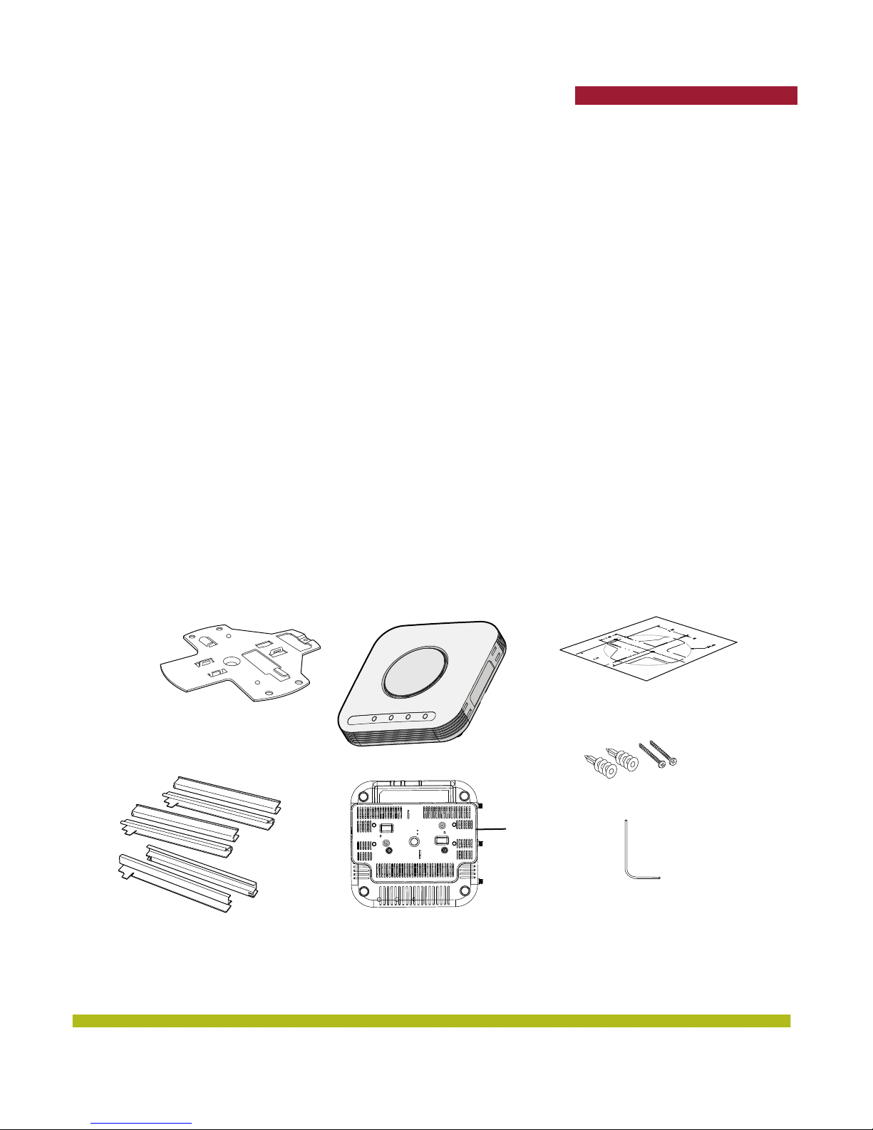
The shipping carton for an MP-82 contains the following items:
1. One MP-82
2. Ceiling mounting kit including:
❑ One universal mounting bracket
❑ Mounting template
❑ screws
❑ T-bar clamps
3. Installation manual
Before you begin installation:
1. Open the carton and carefully remove the contents.
2. Place the packing materials back in the carton and save the carton.
3. Verify that you received each item in the previous list. If any item is missing or damaged, contact
Trapeze Networks.
T-bar clamps
MP-82
Front view
Mounting template
Universal
Mounting
Bracket
Mounting hardware
Factory
attached
bracket
Lock/ unlock tool
Rear view
Indoor Mobility Point™ Quick Start Guide
5
Page 6
Trapeze Networks
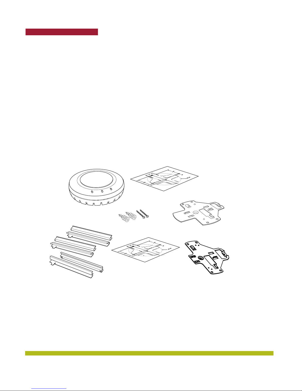
MP-422/432/522 Package Contents
The shipping carton for an MP contains the following items:
1. One MP
2. Mounting kit including:
❑ One mounting bracket (attached to the MP)
The MP-522 package contains a specific mounting bracket (attached to the MP)
❑ One paper mounting template (used for marking cutting areas and screw holes)
The MP-522 package contains a specific mounting template with different dimensions than the
template used for the MP-422 and MP-432.
❑ One two-piece 14.2-millimeter (9/16-inch) T-bar clamp
❑ One two-piece 15.9-millimeter (5/8-inch) T-bar clamp
❑ One two-piece 23.9-millimeter (15/16-inch) T-bar clamp
❑ Two #6 sheet metal screws and two drywall anchors
3. One documentation pack that includes quick mounting instructions and a user guide.
Figure 1–1. Shipping Carton Contents
Mounting template
Mobility Point
Mounting hardware
MP-522 mounting
template
T-bar clamps
MP-422 and MP-432
mounting bracket
840-9502-0001
MP-522 mounting
bracket (included
with MP-522 and
MP-522E orders)
6
Indoor Mobility Point™ Quick Start Guide
Page 7
Trapeze Networks
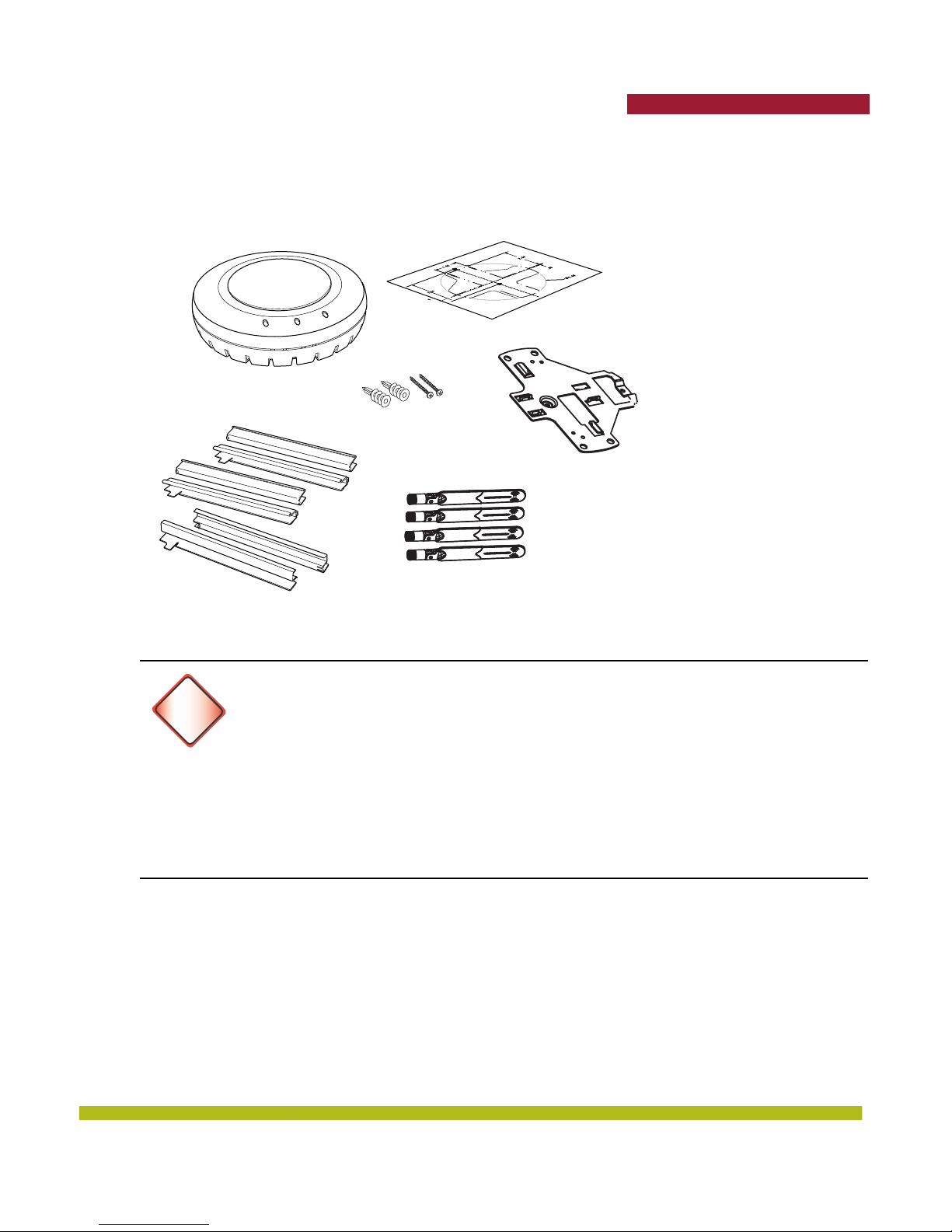
MP-522E Package Contents
The shipping carton for an MP-522E contains all of the items listed in the MP-422/432/522 with the
addition of 4 Omni-directional antennas.
Mounting template
Mobility Point
Mounting hardware
Earthquake safety
mounting bracket
Four ANT-7360P-IN antennas
T-bar clamps
The Trapeze-approved antennas listed in the table below can also be used with the MP-522E.
FCC Caution
To reduce potential radio interference to other users, the antenna type and its gain
Warning!
should be so chosen that the equivalent isotropically radiated power (e.i.r.p) is not more
than that permitted for successful communication.
This device has been designed to operate with the antennas listed below, and having a
maximum gain of [23.5] dB. Antennas not included in this list or having a gain greater
than [23.5] dB are strictly prohibited for use with this device. The required antenna
impedance is 50 ohms.
The tested/certified antennas are equipped with Reverse-SMA or N-type jacks.
Indoor Mobility Point™ Quick Start Guide
7
Page 8
Trapeze Networks
Table 1– 1. MP-522E Trapeze-Approved Antennas
Trapeze Model Number Part Number
ANT-7360A-OUT MMO24580608NF 6/8 Omni 1 N-type Jack
MFB24006 6/ no element Omni 1 N-type Jack
MFB24004 4/ no element Omni 1 N-type Jack
50 1360 no element/ 8 Omni 1 N-type Jack
MMO58007NF no element/ 7 Omni 1 N-type Jack
ECO6-5500 no element/ 6 Omni 1 N-type Plug
M6060060MO13620O 6/6 Omni 6 RP-SMA Plug
ANT-77555-OUT S24517PT36RSM 8/10.7 Panel 3 RP-SMA Plug
T24060MP13620 6/ no element Panel 3 RP-SMA Plug
T58070MP13620 no element/ 7 Panel 3 RP-SMA Plug
M6060070MP13620 6/7 Panel 6 RP-SMA Plug
ANT-74520-OUT S245112PT36RSM 10.9/13.5 Panel 3 RP-SMA Plug
ANT-5007-OUT MA-WA56-DP25NB no element /23.5 Panel 2 N-type Jack
ANT-7360P-IN FDE_ACBSMA-BGP 3/5 Omni (Paddle
S24493TS 3/4 Omni 3 RP-SMA
M6025040MO1D3620 2.5/4 Omni 3 RP-SMA
M6025040MO1D2420M 2.5/4 Omni 3 RP-SMA
2.4GHz / 5GHz
dBI Gain
Antenna Type
or Rubber
Ducky
Number of
Connectors
1 RP-SMA
Connector Type
Always install the four MP-522E antennas before supplying power to the MP. Failure to
do so can cause damage to the unit.
Warning!
The operation of antenna ANT-5007-OUT is not allowed in India.
Installation Requirements and Recommendations
For best results, follow these requirements and recommendations before installing an MP.
RingMaster Network Plan and Work Orders
If you are using RingMaster to plan your Trapeze Networks Mobility System installation, you might
want to create and verify a network plan for the entire Trapeze Network installation and generate an
MP work order before installing MPs. A network plan and the MP work orders generated from it
provide the following information about MP installation and configuration:
❑ Number of MPs required for adequate WLAN capacity in each coverage area
❑ Detailed installation location for each MP
❑ Settings for all MPs in the WLAN
8
Indoor Mobility Point™ Quick Start Guide
Page 9

Trapeze Networks
MX Recommendation
Trapeze Networks recommends that you install and configure the MX before installing an MP. If the
MX is already installed and configured for the MP, you can immediately verify the cable connection(s)
when you plug the cable(s) into the MP.
An Indoor MP is designed to receive power only from an 802.3af-compliant source, a
Trapeze Networks Mobility Exchange (MX), or a Trapeze-approved power injector.
Warning!
Connecting an MP to a Power over Ethernet (PoE) device not approved by Trapeze
Networks can damage the equipment.
Wall Installation Recommendations
If you plan to install an MP on a partial wall or other vertical surface, orient the top of the MP (the
side with the LEDs) toward the intended coverage area. The radio antennas transmit through the top
of the MP but not through the bottom, where the bracket is located.
This recommendation does not apply if you plan to use external antennas. You can orient the
antennas independently of the MP. Orient an external antenna to face the intended coverage area.
MP Radio Safety Advisories
When you enable the MP radio(s) as part of MX configuration, the radios can receive and transmit
radio frequency energy as soon as you connect the MP to the MX, either directly or through the
network.
Radio Frequency Exposure
Federal Communications Commission (FCC) Docket 96-8 for Spread Spectrum Transmitters specifies
a safety standard for human exposure to radio frequency electromagnetic energy emitted by
FCC-certified equipment. When used with the proper antennas (shipped in the product), Trapeze
Networks MPs meet the uncontrolled environmental limits found in OET-65 and ANSI C95.1-1991.
Proper installation of the MP according to the instructions in this manual will result in user exposure
that is below the FCC recommended limits.
Federal Communication Commission Interference Statement
This equipment has been tested and found to comply with the limits for a Class B digital device,
pursuant to Part 15 of the FCC Rules. These limits are designed to provide reasonable protection
against harmful interference in a residential installation. This equipment generates, uses and can
radiate radio frequency energy and, if not installed and used in accordance with the instructions, may
cause harmful interference to radio communications. However, there is no guarantee that
interference will not occur in a particular installation. If this equipment does cause harmful
interference to radio or television reception, which can be determined by turning the equipment off
and on, the user is encouraged to try to correct the interference by one of the following measures:
❑ Reorient or relocate the receiving antenna.
❑ Increase the separation between the equipment and receiver.
❑ Connect the equipment into an outlet on a circuit different from that to which the receiver is
connected.
❑ Consult the dealer or an experienced radio/TV technician for help.
Indoor Mobility Point™ Quick Start Guide
9
Page 10
Trapeze Networks
This device complies with Part 15 of the FCC Rules. Operation is subject to the following two
conditions: (1) This device may not cause harmful interference, and (2) this device must accept any
interference received, including interference that may cause undesired operation.
FCC Caution
Any changes or modifications not expressly approved by the party responsible for
!
Caution
!
Caution
!
Caution
compliance could void the user's authority to operate this equipment. This device and
its antenna(s) must not be co-located or operating in conjunction with any other
antenna or transmitter.
FCC and IC Radiation Exposure Statement
This equipment complies with FCC and IC RSS-102 radiation exposure limits set
forth for an uncontrolled environment. This equipment should be installed and
operated with minimum distance 50cm (19.7 inches) between the radiator and your
body.
FCC Caution for the MP-522E
To comply with FCC part 15 rules in the United States, the system must be
professionally installed to ensure compliance with the Part 15 certification. It is the
responsibility of the operator and professional installer to ensure that only certified
systems are deployed in the United States. The use of the system in any other
combination (such as co-located antennas transmitting the same information) is
expressly forbidden.
The device could automatically discontinue transmission in case of absence of
information to transmit, or operational failure. Note that this is not intended to
prohibit transmission of control or signaling information or the use of repetitive codes
where required by the technology.
The device for the band 5150-5250 MHz is only for indoor usage to reduce potential for
harmful interference to co-channel mobile satellite systems.
The maximum antenna gain permitted (for devices in the bands 5250-5350 MHz and
5470-5725 MHz) to comply with the e.i.r.p. limit.
The maximum antenna gain permitted (for devices in the band 5725-5825 MHz) to
comply with the e.i.r.p. limits specified for point-to-point and non point-to-point
operation as appropriate, as stated in section A9.2(3).
High-power radars are allocated as primary users (meaning they have priority) of the
bands 5250-5350 MHz and 5650-5850 MHz and these radars could cause interference
and/or damage to LE-LAN devices
10
Indoor Mobility Point™ Quick Start Guide
Page 11
Trapeze Networks
IC Statement for the MP-522E- This Class B digital apparatus complies with
Canadian ICES-003.
!
Caution
Operation is subject to the following two conditions: (1) this device may not cause
interference, and (2) this device must accept any interference, including interference
that may cause undesired operation of the device.
Cet appareil numérique de la classe B est conforme á la norme NMB-003 du Canada.
Additional Radio Safety Advisories
For translations of warnings, see the TrapezeRegulatory Guide. The Trapeze Regulatory Guide is
located at http://www.trapezenetworks.com/support/contact_support/ and can be downloaded
in PDF format.
In the U.S., locate the MP and any externally attached antennas a minimum of 50cm
(19.7 inches) away from people. This safety warning conforms with FCC radio
Warning!
frequency exposure limits for dipole antennas such as those used in the MP.
Warning!
Warning!
Do not operate the MP near unshielded blasting caps or in an otherwise explosive
environment unless the device has been modified for such use by qualified personnel.
Before using a wireless device in a hazardous location, consult the local codes,
national codes, and safety directors of the location for usage constraints
Do not touch or move the MP when the antennas are transmitting or receiving.
Do not hold any radio device so that the antenna is very close to or touching the face,
eyes, or other exposed body part while the radio antenna is transmitting.
Indoor Mobility Point™ Quick Start Guide
11
Page 12
Trapeze Networks
Cabling Requirements
Do not connect or disconnect cables or otherwise work with the MP hardware during
periods of lightning activity.
Warning!
The MP is intended for indoor use only. Do not install the device outdoors, unless you
Note:
Note:
install it with a Trapeze Networks outdoor MP enclosure.
To reduce the possibility of connection interference caused by dust, clean the Cat 5
connector pins before inserting a cable into an MP.
Category 5 cable with straight-through signaling must be installed at the site before you install an
MP. A single connection requires one cable. A dual-homed connection requires two cables.
Mounting an MP on a solid surface requires Cat 5 cable that does not have strain relief. For
installation on all other surfaces, use a Cat 5 cable with or without strain relief.
Installing an Indoor Mobility Point
Installation Hardware and Tools
The table below lists the mounting hardware and tools required for each type of MP installation.
Table 1– 2. Required Mounting Hardware and Tools
Mounting Option Required Hardware and Tools
Mounting template Yes
Universal mounting bracket Yes
T-bar clamp — A T-bar clamp is not required for a 23.9-millimeter
Suspended ceiling—flush
ceiling tiles
(15/16-inch) T-bar ceiling with flush ceiling tiles.
Box cutter No
Small screwdriver (3-millimeter or 1/8-inch) No
small-pointed instrument or a paperclip No
Included with
the Product
Yes
12
Indoor Mobility Point™ Quick Start Guide
Page 13
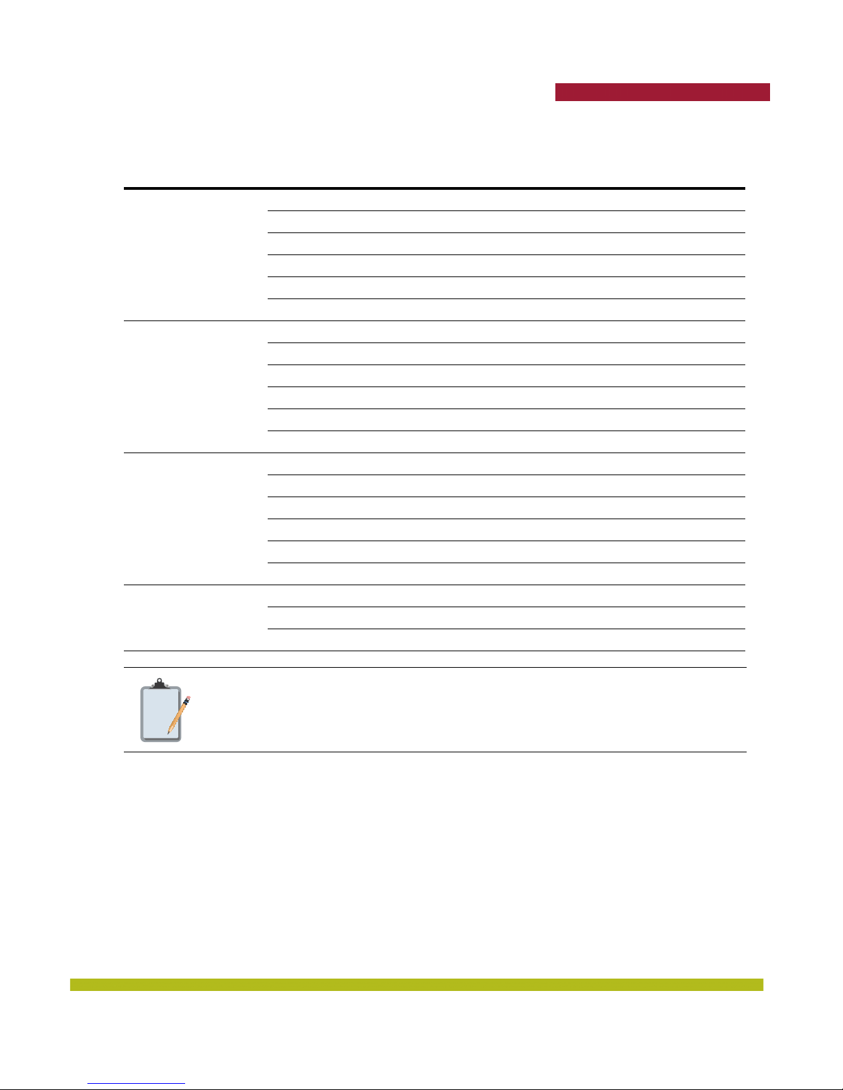
Table 1– 2. Required Mounting Hardware and Tools
Trapeze Networks
Mounting Option Required Hardware and Tools
Mounting template Yes
Universal mounting bracket Yes
Suspended ceiling—drop
ceiling tiles
Junction box
Solid wall or ceiling
Tabletop
T-bar clamp Yes
Box cutter No
Small screwdriver (3-millimeter or 1/8-inch) No
small-pointed instrument or a paperclip No
Junction box No
Two #6-32 x 1-inch machine screws Yes
Universal mounting bracket Yes
Small screwdriver (3-millimeter or 1/8-inch) No
#2 Phillips-head screwdriver No
small-pointed instrument or a paperclip No
Two #6 sheet metal screws and two drywall anchors Yes
Universal mounting bracket Yes
Hammer No
Small screwdriver (3-millimeter or 1/8-inch) No
#2 Phillips-head screwdriver No
small-pointed instrument or a paperclip No
Universal mounting bracket Yes
Small screwdriver (3-millimeter or 1/8-inch) No
small-pointed instrument or a paperclip No
Included with
the Product
Indoor MPs are UL2043 plenum rated, so it also can be installed in the space above
Note:
the ceiling if preferred.
MP-82 Ceiling Mount Instructions
Suspended Ceiling Installation — Flush Ceiling Tiles MP-82
1. Select an installation location centered over a T-bar in the ceiling.
2. Cut a hole as follows in the ceiling tile for the Cat 5 cable:
a. Place the mounting template over the area where you plan to install the MP.
b. Use the box cutter to cut along the line marking the opening for the port connectors.
c. Remove the mounting template and the material you cut from the ceiling panel.
3. Determine whether to install a T-bar clamp onto the ceiling T-bar:
Indoor Mobility Point™ Quick Start Guide
13
Page 14
Trapeze Networks
❑ If the T-bar width is 14.2 millimeter (9/16 inches), you need to install the 14.2-millimeter (9/
16 inches) T-bar clamp. Go to step 4.
❑ If the T-bar width is 23.9 millimeter (15/16 inches), the universal mounting bracket fits
directly onto the T-bar. Go to step 5.
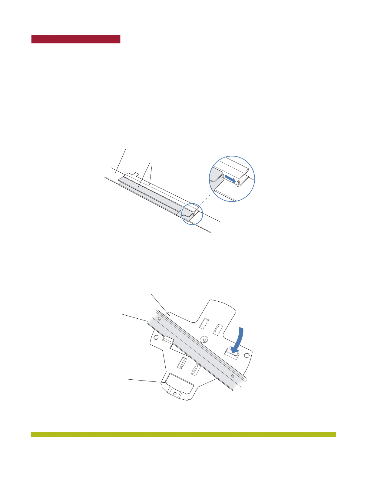
4. Install the 14.2-millimeter (9/16-inch) T-bar clamp onto the ceiling T-bar as shown in Figure 1–5.
a. Slide each half of the clamp onto the T-bar so that the clamp lip is fully on the T-bar.
b. Slide the two halves of the clamp toward each other until the tabs are inserted completely into
the holes and the clamp fits snugly on the T-bar.
T-bar
T-bar clamp halves
Slide together
5. Install the universal mounting bracket as follows onto the T-bar or T-bar clamp.
a. As shown in the figure below, place the universal mounting bracket against the T-bar or clamp
so that the two screw holes face downward and the two T-bar flanges face upward and are
adjacent to the T-bar edges.
Figure 1–3. Step 7—Top View
Universal mounting
bracket
Figure 1–2. Step 4—Installing a T-bar Clamp
T-bar
Port connector
opening
(Viewed from above ceiling tiles, looking down.)
14
Indoor Mobility Point™ Quick Start Guide
Page 15
Trapeze Networks
b. Properly align the bracket for mounting by placing the bracket so the port connector opening is
to the left of the hole you cut for the cables.
c. Rotate the universal mounting bracket clockwise until the flanges snap into place on the T-bar
or clamp as shown in the figure below.
Universal mounting bracketPort connector
opening
T- b a r
6. Pull the Cat 5 cable about 15 centimeters (about 6 inches) out of the hole in the ceiling tile and
through the port connector opening to create enough slack to insert the cable.
7. Insert the Cat 5 cable into the connector.
8. Install the Kensington lock, if you plan to use one.
a. Loop the Kensington lock cable around an object that cannot be moved or damaged by a person
pulling on the cable.
b. Insert the key into the Kensington lock.
c. Insert the Kensington lock into the security slot on the MP.
d. Rotate the key right or left to secure the lock to the MP.
e. Pull on the lock to verify that it is secured to the MP.
f. Remove the key.
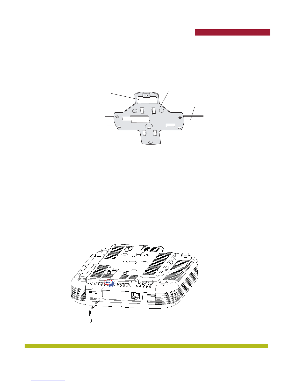
9. Unlock the MP-82 by inserting the lock/unlock tool into the Unlock hole and push until you feel
the internal bracket slide across.
Figure 1–4. Step 7—Bottom View
Indoor Mobility Point™ Quick Start Guide
15
Page 16
Trapeze Networks
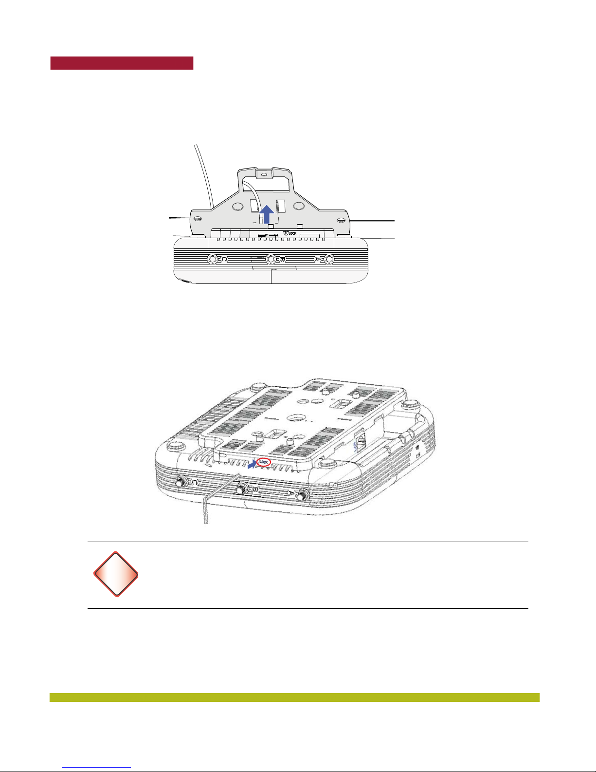
10. Lift the MP into place on the universal mounting bracket as shown below.
Make sure the cable feeds properly into the ceiling as you lift the device, and does not become
trapped between the MP and the bracket.
11. Lock the MP onto the bracket by inserting the lock/unlock tool into the Lock hole on the MP and
push until you feel the internal bracket slide across.
To prevent possible damage to the MP, make sure the device is fully locked onto the
bracket before releasing it.
Warning!
12. To ensure that the MP is fully locked onto the bracket, gently pull down on the MP and attempt to
rotate it from side to side.
13. If the MP comes off the bracket, relock the device onto the bracket.
16
Indoor Mobility Point™ Quick Start Guide
Page 17
14. If the MP requires an external antenna, install and connect the antenna.
MP-82 Wall Mount Installation
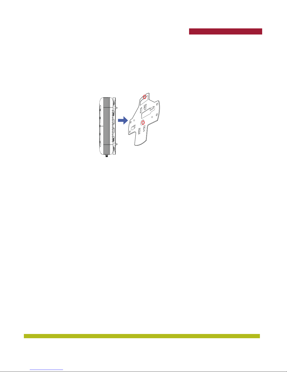
Use the included universal mounting bracket to wall mount the MP.
1. Screw the universal mounting bracket directly to a wall.
❑ If mounting to drywall, use two screws and two wall anchors in the provided holes on the
bracket that are circled in red below.
Trapeze Networks
2. Connect the Ethernet cable (for power and network connection) to the port on the back of the
MP-82.
3. Unlock the MP by inserting the lock/unlock tool into the Unlock hole and push until you feel the
internal bracket slide across.
4. Mount the MP-82 onto the mounting bracket.
5. Lock the MP onto the bracket by inserting the lock/unlock tool into the Lock hole on the MP and
push until you feel the internal bracket slide across
Installing an Indoor MP-422/432/522
Suspended Ceiling Installation — Flush Ceiling Tiles for the MP-422/432/522
1. Select an installation location centered over a T-bar in the ceiling.
2. Cut a hole as follows in the ceiling tile for the Cat 5 cable:
a. Place the mounting template over the area where you plan to install the MP.
b. Use the box cutter to cut along the line marking the opening for the port connectors.
c. Remove the mounting template and the material you cut from the ceiling panel.
3. Determine whether to install a T-bar clamp onto the ceiling T-bar:
❑ If the T-bar width is 14.2 millimeter (9/16 inches), you need to install the 14.2-millimeter (9/
16 inches) T-bar clamp. Go to step 4.
❑ If the T-bar width is 23.9 millimeter (15/16 inches), the universal mounting bracket fits
directly onto the T-bar. Go to step 5.
4. Install the 14.2-millimeter (9/16-inch) T-bar clamp onto the ceiling T-bar as shown in Figure 1–5.
a. Slide each half of the clamp onto the T-bar so that the clamp lip is fully on the T-bar.
b. Slide the two halves of the clamp toward each other until the tabs are inserted completely into
the holes and the clamp fits snugly on the T-bar.
Indoor Mobility Point™ Quick Start Guide
17
Page 18
Trapeze Networks
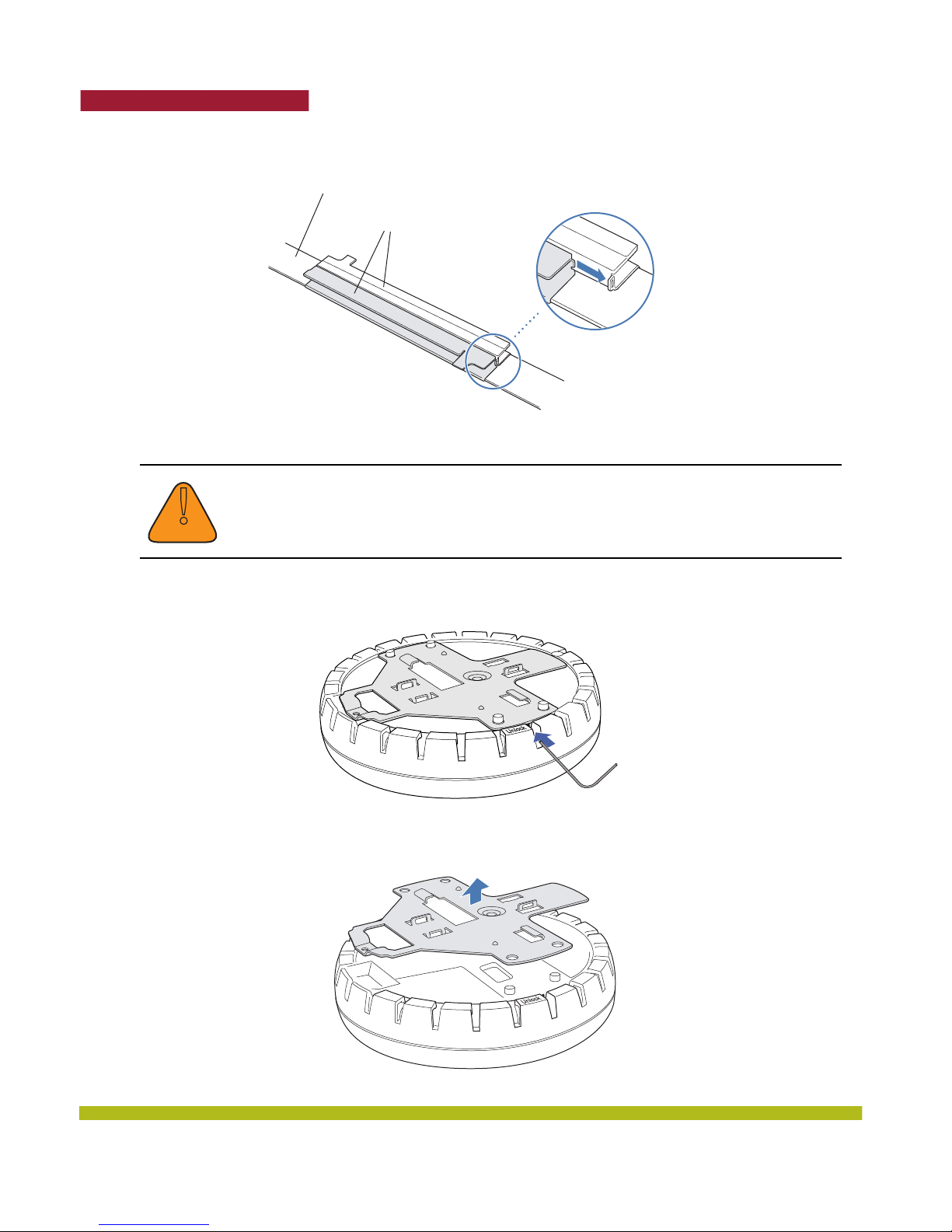
Figure 1–5. Step 4—Installing a T-bar Clamp
T-bar
Slide together
T-bar clamp halves
5. Unlock the universal mounting bracket from the MP by inserting the lock/unlock tool into the
Unlock hole on the MP as shown in Figure 1–6 below.
Use a small-pointed instrument or a paperclip to unlock the MP. Do not use a
screwdriver because it may cause damage to the MP lock mechanism or electronic
!
Caution
D
components. Do not use excessive force when inserting a tool into the Unlock or
Lock hole.
Figure 1–6. Step 5—Unlocking the Bracket
6. Remove the bracket as shown in Figure 1–7 below.
Figure 1–7. Step 6—Removing the Bracket
18
Indoor Mobility Point™ Quick Start Guide
Page 19
Trapeze Networks
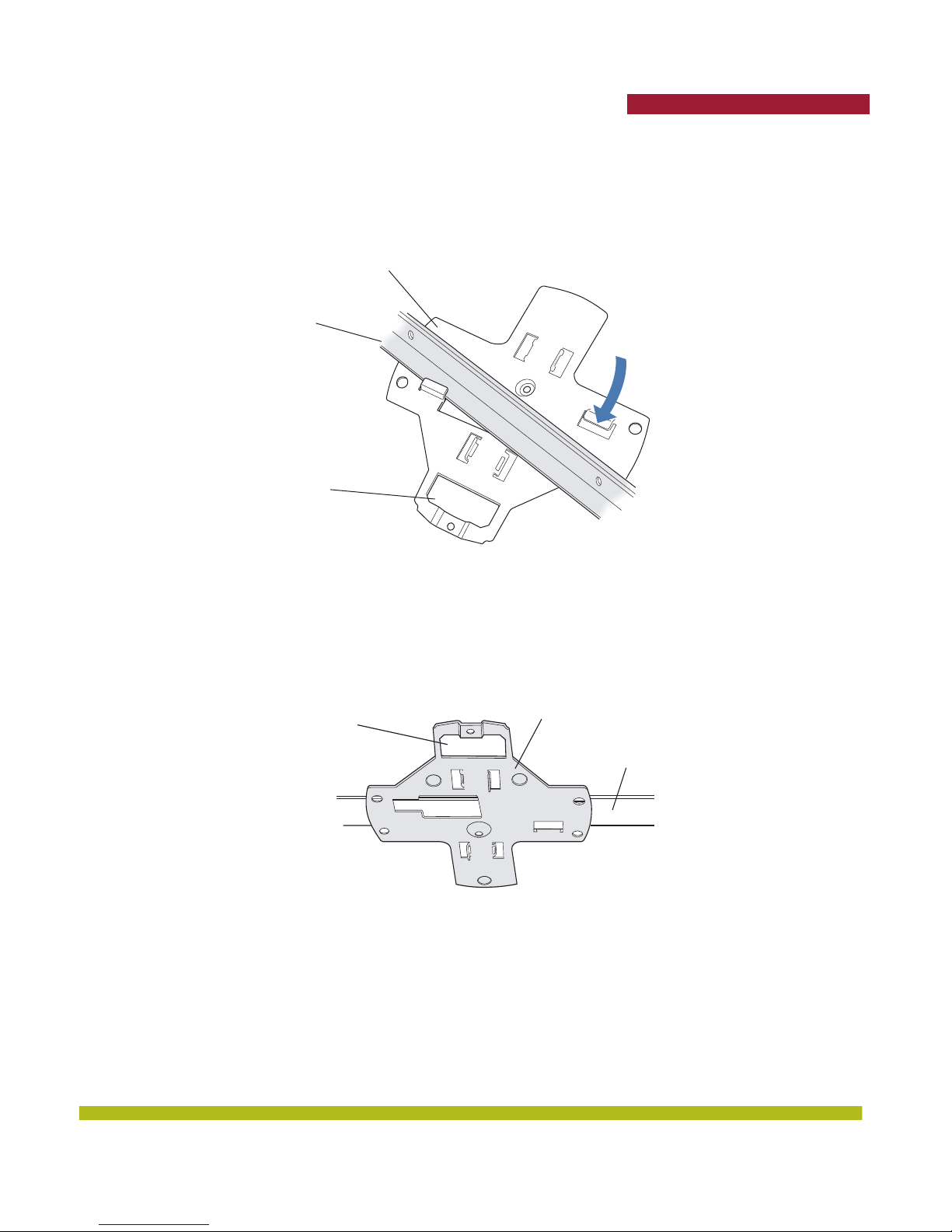
7. Install the universal mounting bracket as follows onto the T-bar or T-bar clamp.
a. As shown in Figure 1–8 below, place the universal mounting bracket against the T-bar or clamp
so that the two screw holes face downward and the two T-bar flanges face upward and are
adjacent to the T-bar edges.
Universal mounting
bracket
T-bar
Port connector
opening
b. Properly align the bracket for mounting by placing the bracket so the port connector opening is
to the left of the hole you cut for the cables.
c. Rotate the universal mounting bracket clockwise until the flanges snap into place on the T-bar
or clamp as shown below.
Figure 1–9. Step 7—Bottom View
Figure 1–8. Step 7—Top View
Universal mounting bracketPort connector
opening
Indoor Mobility Point™ Quick Start Guide
T- b a r
19
Page 20
Trapeze Networks
MP-522-Specific Optional Earthquake Safety Step
Note:
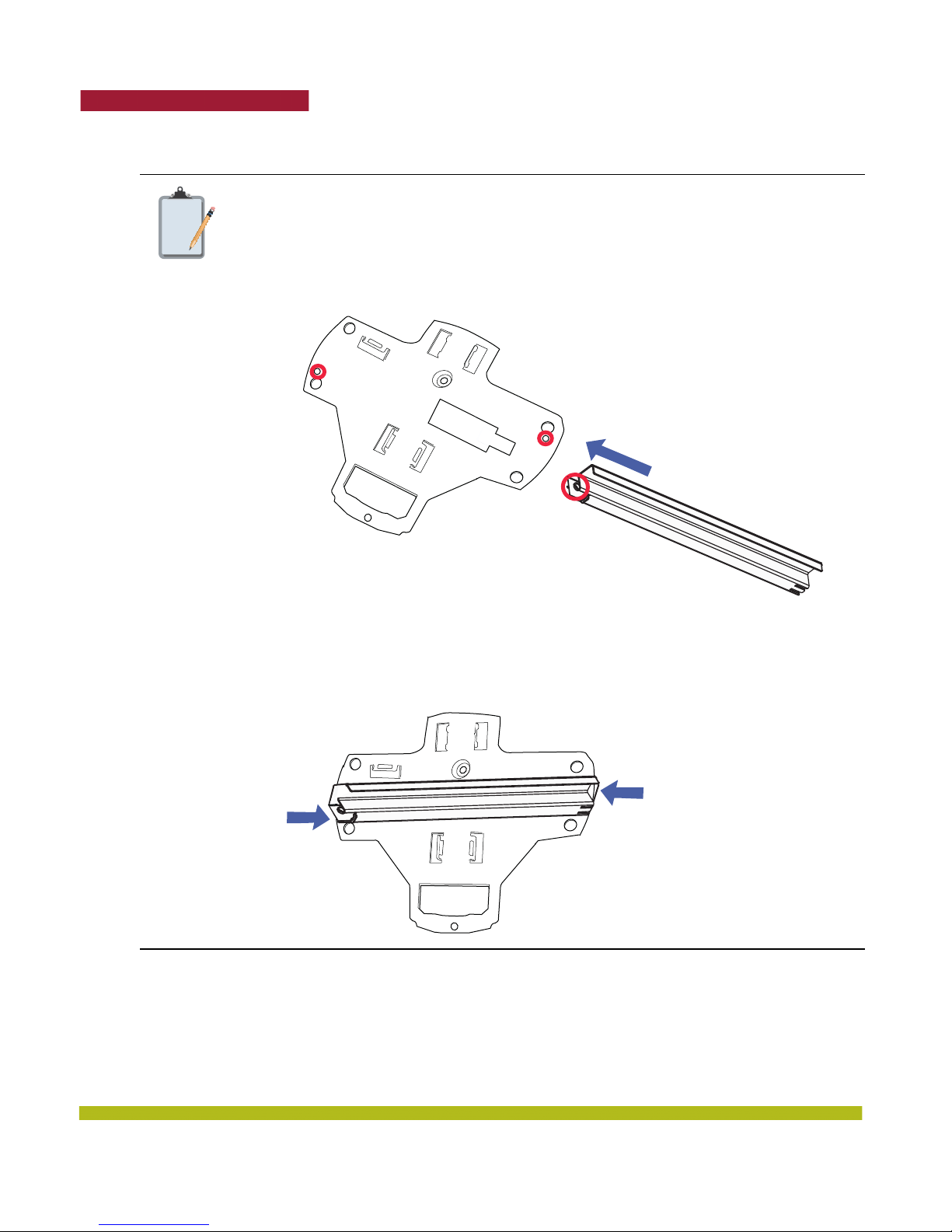
At this point, once you have the T-bar installed and the universal mounting bracket
snapped into place, you have the option of securing the bracket for earthquake safety
using the two supplied M3 pan head threaded screws.
Note that the T-bars and the universal mounting bracket in the MP-522 Installation
Kit have two additional screw holes as shown below.
When the universal mounting bracket is snapped into place, the holes will align.
Screw the two M3 pan head threaded screws into the holes. The screws will hold the
T-bar and universal mounting bracket together in the event of an earthquake. The
MP-522 is then locked securely into place on the secured universal mounting bracket.
M3 pan head screw
M3 pan head screw
8. Pull the Cat 5 cable about 15 centimeters (about 6 inches) out of the hole in the ceiling tile and
through the port connector opening to create enough slack to insert the cable.
9. Insert the Cat 5 cable into the connector.
10. Install the Kensington lock, if you plan to use one.
20
Indoor Mobility Point™ Quick Start Guide
Page 21
Trapeze Networks
a. Loop the Kensington lock cable around an object that cannot be moved or damaged by a person
pulling on the cable.
b. Insert the key into the Kensington lock.
c. Insert the Kensington lock into the security slot on the MP.
d. Rotate the key right or left to secure the lock to the MP.
e. Pull on the lock to verify that it is secured to the MP.
f. Remove the key.
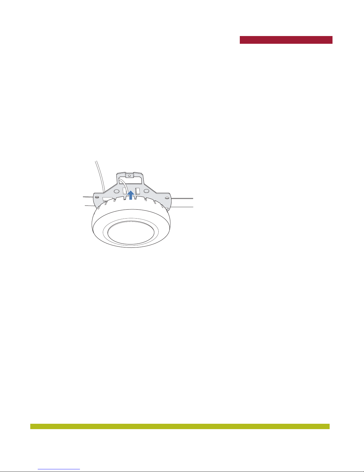
11. Lift the MP into place on the universal mounting bracket as shown in Figure 1–10 below.
Make sure the cable feeds properly into the ceiling as you lift the device, and does not become
trapped between the MP and the bracket.
Figure 1–10. Step 10—Placing the MP on the Bracket
Indoor Mobility Point™ Quick Start Guide
21
Page 22
Trapeze Networks
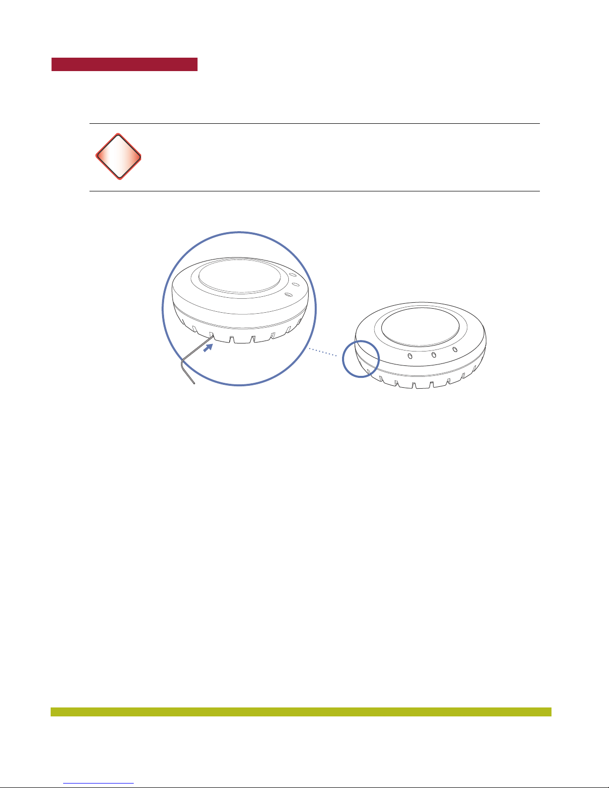
12. Lock the MP onto the bracket by inserting a small-pointed instrument or a paperclip into the
Lock hole on the MP as shown in Figure 1–11 below.
To prevent possible damage to the MP, make sure the device is fully locked onto the
bracket before releasing it.
Warning!
Lock
13. To ensure that the MP is fully locked onto the bracket, gently pull down on the MP and attempt to
rotate it from side to side.
14. If the MP comes off the bracket, relock the device onto the bracket as described in step 12 on
page 22.
15. If the MP requires an external antenna, install and connect the antenna.
Suspended Ceiling Installation—Drop Ceiling Tiles
(For required mounting hardware and tools, see Table 1– 2 on page 12.)
1. Select an installation location that is centered over a T-bar in the ceiling.
2. Cut a hole as follows in the ceiling tile for the Cat 5 cable:
a. Place the mounting template over the area where you plan to install the MP.
b. Use the box cutter to cut along the line marking the opening for the port connectors.
c. Remove the mounting template and the material you cut from the ceiling panel.
3. Install the T-bar clamp that fits the T-bar:
a. Slide each half of the clamp onto the T-bar so that the clamp lip is fully on the T-bar.
b. Slide the two halves of the clamp toward each other until the tabs are inserted completely into
the holes and the clamp fits snugly on the T-bar.
Figure 1–11. Step 12—Locking the Bracket
22
Indoor Mobility Point™ Quick Start Guide
Page 23
Trapeze Networks
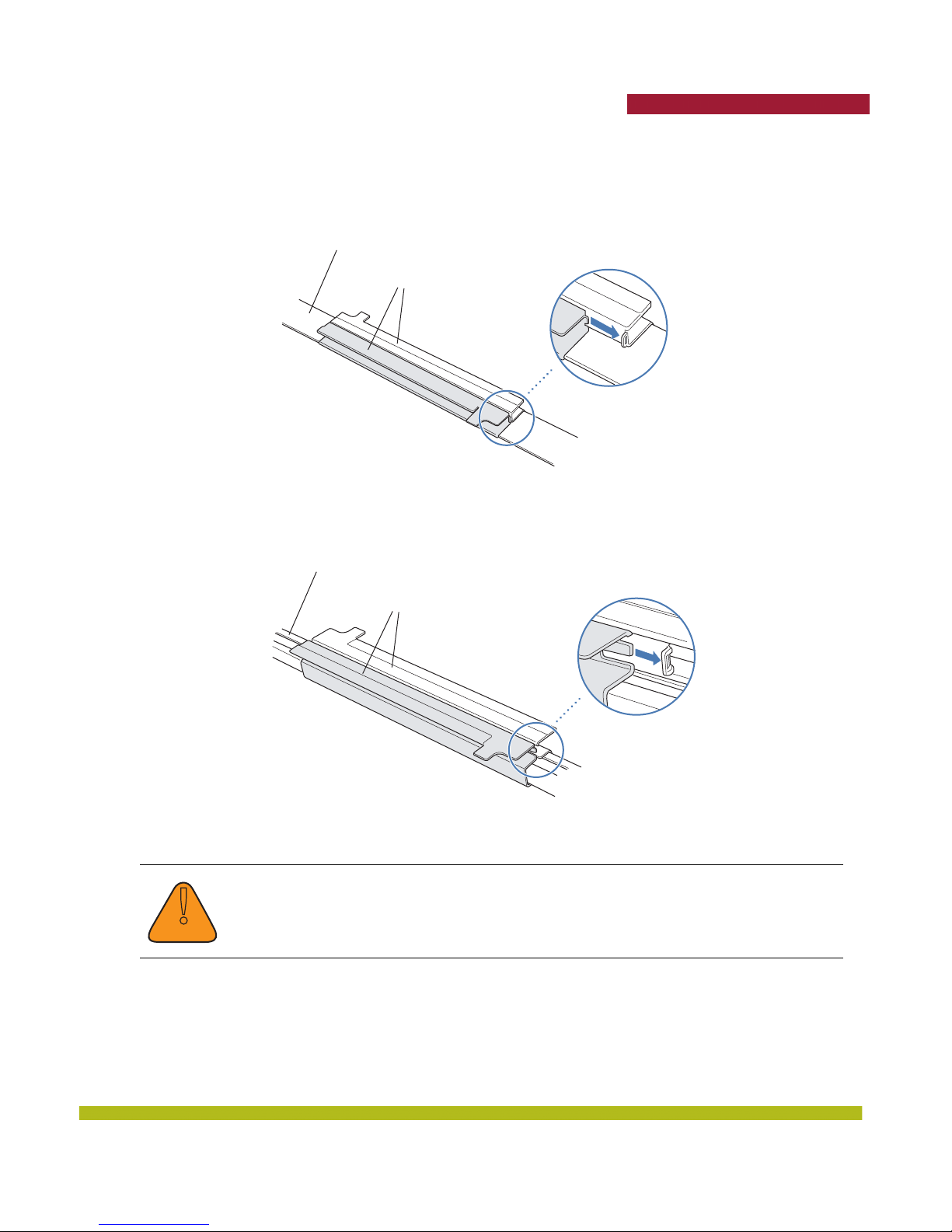
Figure 1–12 shows an example for a 23.9-millimeter (15/16-inch) T-bar. Figure 1–13 shows an
example for a 15.9-millimeter (5/8-inch) T-bar.
T-bar
T-bar clamp halves
Slide together
Figure 1–13. Step 3—Installing the T-bar Clamp for a 15.9-millimeter (5/8-inch) T-bar
T-bar
Figure 1–12. Step 3—Installing the T-bar Clamp for a 23.9-millimeter (15/16-inch) T-bar
T-bar clamp halves
Slide together
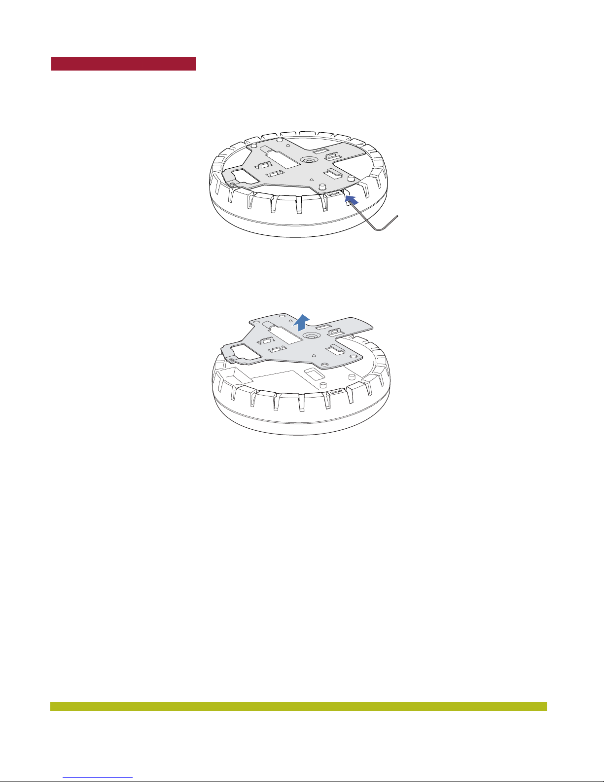
4. Unlock the universal mounting bracket from the MP by inserting a small-pointed instrument or a
paperclip into the Unlock hole on the MP as shown in Figure 1–14 below.
Use a small-pointed instrument or a paperclip to unlock the MP. Do not use a
screwdriver because it may cause damage to the MP lock mechanism or electronic
!
Caution
components. Do not use excessive force when inserting a tool into the Unlock or Lock
hole.
Indoor Mobility Point™ Quick Start Guide
23
Page 24
Trapeze Networks
Figure 1–14. Step 4—Unlocking the Bracket
5. Remove the bracket as shown in Figure 1–15 below.
Figure 1–15. Step 5—Removing the Bracket
24
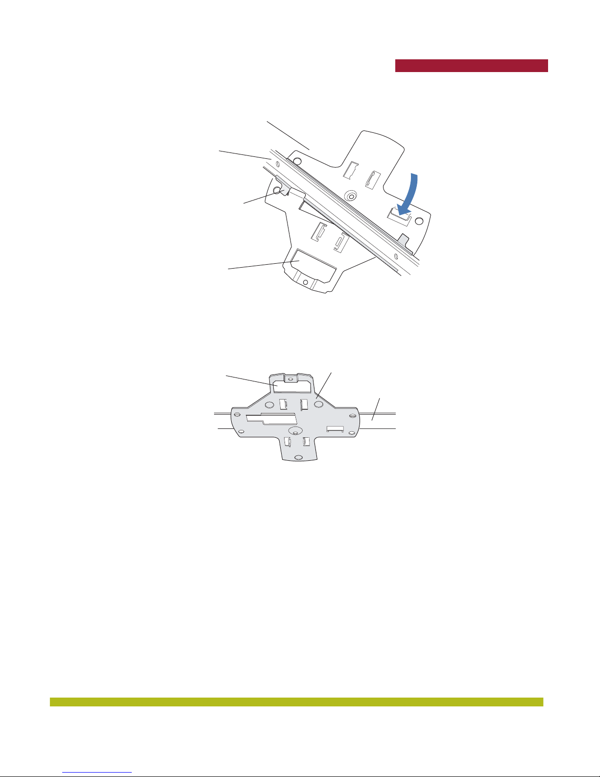
6. Install the universal mounting bracket as follows onto the T-bar clamp:
a. As shown in Figure 1–16, place the universal mounting bracket against the T-bar clamp so that
the two screw holes face downward and the two T-bar flanges face upward and are adjacent to
the T-bar edges.
b. Properly align the bracket for mounting by placing the bracket so that the port connector
opening is to the left of the hole you cut for the cables.
c. Rotate the universal mounting bracket clockwise until the flanges snap into place on the T-bar
clamp as shown below.
Indoor Mobility Point™ Quick Start Guide
Page 25
Trapeze Networks
Figure 1–16. Step 6—Top View
Universal mounting
bracket
T- bar
T-bar clamps
(attached
to T-bar)
Port connector
opening
(Viewed from above ceiling tiles, looking down.)
Figure 1–17. Step 6—Bottom View
opening
Universal mounting bracketPort connector
T- b a r
7. Pull the Cat 5 cable about 15 centimeters (about 6 inches) out of the hole in the ceiling tile and
through the port connector opening to create enough slack to insert the cable.
8. Insert the Cat 5 cable into the connector.
9. Install the Kensington lock, if you plan to use one.
a. Loop the Kensington lock cable around an object that cannot be moved or damaged by a person
pulling on the cable.
b. Insert the key into the Kensington lock.
c. Insert the Kensington lock into the security slot on the MP.
d. Rotate the key right or left to secure the lock to the MP.
e. Pull on the lock to verify that it is secured to the MP.
f. Remove the key.
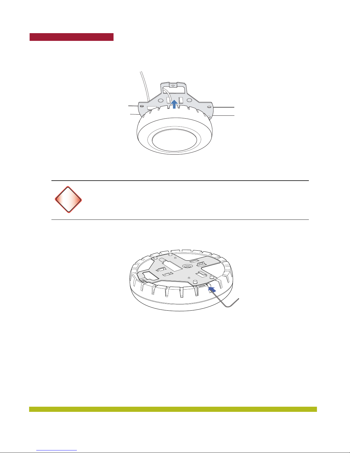
10. Lift the MP into place on the universal mounting bracket as shown in Figure 1–18.
Make sure the cable feeds properly into the ceiling as you lift the device, and does not become
trapped between the MP and the bracket.
Indoor Mobility Point™ Quick Start Guide
25
Page 26
Trapeze Networks
Figure 1–18. Step 9—Placing the MP on the Bracket
11. Lock the MP onto the bracket by inserting a small-pointed instrument or a paperclip into the
Lock hole on the MP as shown in Figure 1–19 below.
To prevent possible damage to the MP, make sure the device is fully locked onto the
bracket before releasing it.
Warning!
12. To ensure that the MP is fully locked onto the bracket, gently pull down on the MP and attempt to
rotate it from side to side.
If the MP comes off the bracket, relock the device onto the bracket as described in step 11 on
page 26.
13. If the MP requires an external antenna, install and connect the antenna.
Figure 1–19. Step 10—Locking the Bracket
26
Indoor Mobility Point™ Quick Start Guide
Page 27
Trapeze Networks
Junction Box Installation
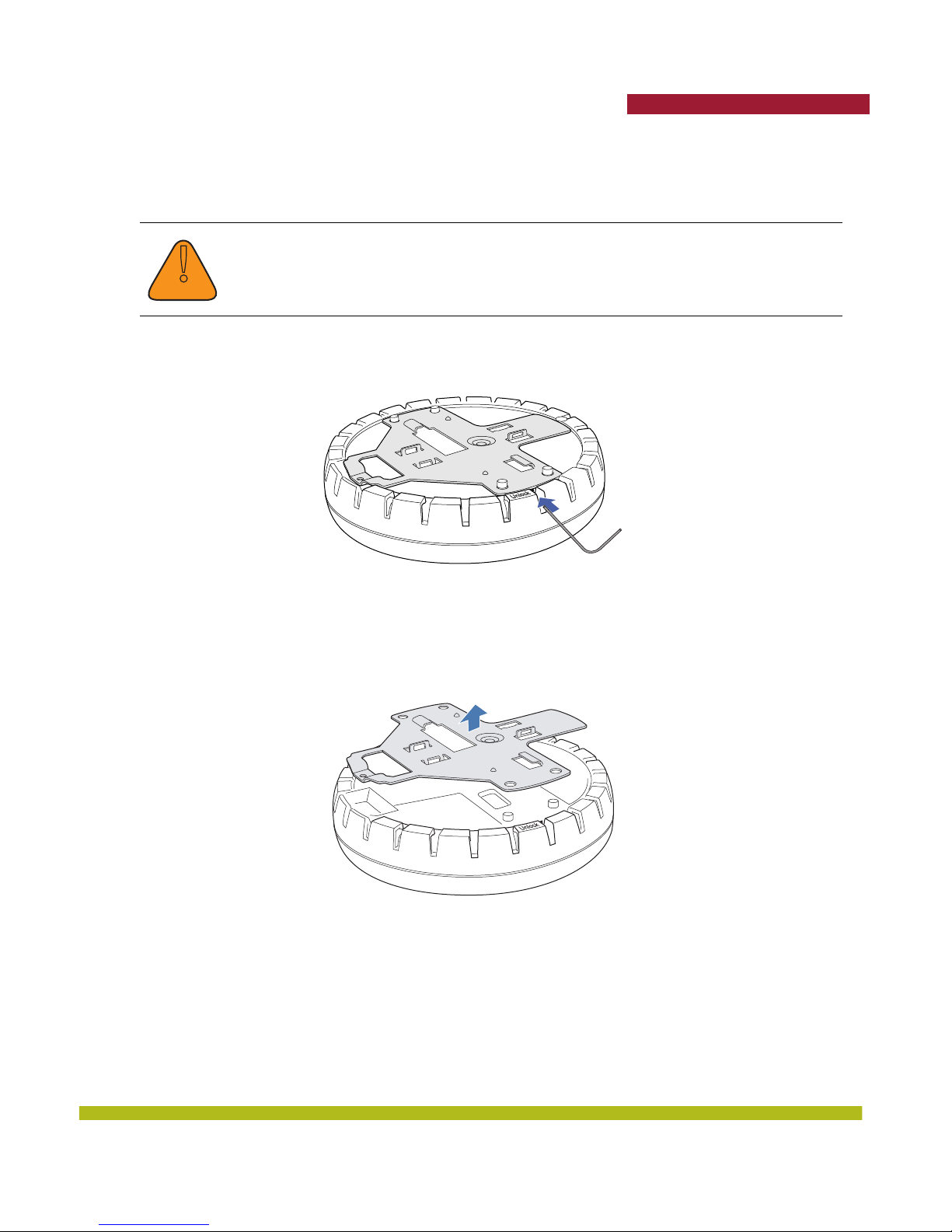
1. Unlock the universal mounting bracket from the MP by inserting a small-pointed instrument or a
paperclip into the Unlock hole on the MP as shown in Figure 1–20.
Use a lock/unlock tool to unlock the MP. Do not use a screwdriver because it may cause
damage to the MP lock mechanism or electronic components. Do not use excessive
force when inserting a tool into the Unlock or Lock hole.
!
Caution
Figure 1–20. Step 1—Unlocking the Bracket
2. Remove the bracket as shown in Figure 1–21.
Figure 1–21. Step 2—Removing the Bracket
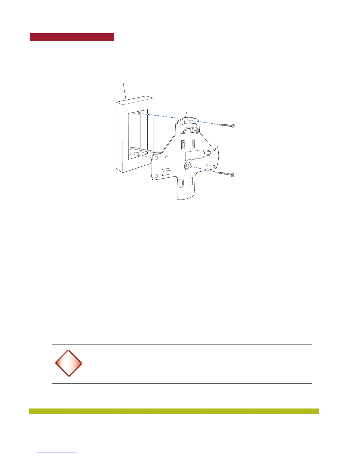
3. Attach the universal mounting bracket to the junction box as shown in Figure 1–22:
a. Place the universal mounting bracket against the junction box so that the two screw holes face
the junction box and align over the screw holes in the box.
b. Insert the #6-32 x 1-inch machine screws in the universal mounting bracket screw holes, and
use a #2 Phillips-head screwdriver to tighten them.
Indoor Mobility Point™ Quick Start Guide
27
Page 28
Trapeze Networks
Figure 1–22. Step 3—Placing the Bracket on the Junction Box
Junction box
Port connector
opening
4. Pull the Cat 5 cable about 15 centimeters (about 6 inches) out of the junction box and through the
port connector opening to create enough slack to insert the cable into the port connectors.
5. Insert the Cat 5 cable into the connector.
6. Install the Kensington lock, if you plan to use one.
a. Loop the Kensington lock cable around an object that cannot be moved or damaged by a person
pulling on the cable.
b. Insert the key into the Kensington lock.
c. Insert the Kensington lock into the security slot on the MP.
d. Rotate the key right or left to secure the lock to the MP.
e. Pull on the lock to verify that it is secured to the MP.
f. Remove the key.
7. Lift the MP into place on the universal mounting bracket.
Make sure the cable feeds properly into the junction box as you lift the device, and does not
become trapped between the MP and the bracket.
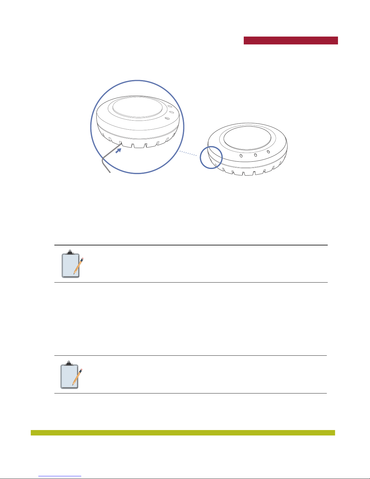
8. Lock the MP onto the bracket by inserting a small-pointed instrument or a paperclip into the
Lock hole on the MP as shown in Figure 1–23.
To prevent possible damage to the MP, make sure the device is fully locked onto the
bracket before releasing it.
Warning!
28
Indoor Mobility Point™ Quick Start Guide
Page 29
Trapeze Networks
Figure 1–23. Step 7—Locking the Bracket
Lock
9. To ensure that the MP is fully locked onto the bracket, gently pull down on the MP and attempt to
rotate it from side to side.
If the MP comes off the bracket, relock the device onto the bracket as described in step 8.
10. If the MP requires an external antenna, install and connect the antenna.
Solid Wall or Ceiling Installation
The solid surface mounting option requires Cat 5 cable that does not have strain relief,
Note:
1. Prepare holes in the wall or ceiling for the universal mounting bracket, using the following steps:
a. Place the paper mounting template over the location to install the MP.
b. Mark the screw hole location(s).
c. If you plan to route the Cat 5 cable externally along the wall or ceiling, mark the locations of
d. If you plan to route the Cat 5 cable through a hole in the wall or ceiling, mark the location of the
Note:
e. Remove the template.
unless you plan to route the cable through a hole in the wall or ceiling. The other
options can use Cat 5 cable with or without strain relief.
both the center screw hole and the screw hole by the port connector opening.
center screw hole only. You cannot use the screw hole by the port connector opening if you cut a
hole for the opening.
Do not mark the four holes on the edges of the bracket. (These are the holes indicated
by the dashed lines in Figure 1–26.) The MP fits into these holes. They are not screw
holes.
Indoor Mobility Point™ Quick Start Guide
29
Page 30
Trapeze Networks
2. Install the drywall anchor(s):
a. Hammer a drywall anchor into each hole, up to the beginning of the threads on the anchor.
b. Screw each anchor the rest of the way into the hole using a #2 Phillips-head screwdriver.
c. Remove the screw from each anchor and save the screw(s) for step 6.
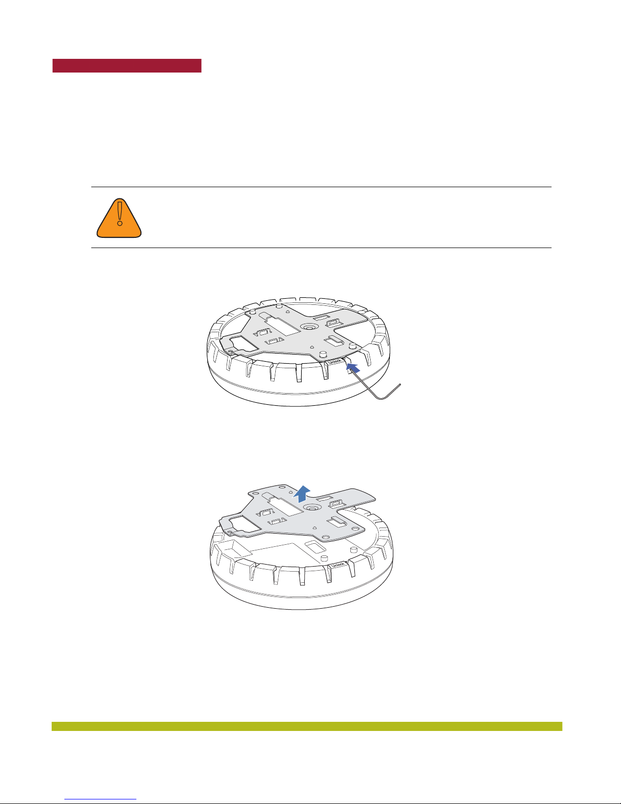
3. Unlock the universal mounting bracket from the MP by inserting the lock/unlock tool into the
Unlock hole on the MP as shown below.
Use the lock/unlock tool to unlock the MP. Do not use a screwdriver because it may
cause damage to the MP lock mechanism or electronic components. Do not use
excessive force when inserting a tool into the Unlock or Lock hole.
!
Caution
Figure 1–24. Step 3—Unlocking the Bracket
4. Remove the bracket as shown in Figure 1–25.
Figure 1–25. Step 4—Removing the Bracket
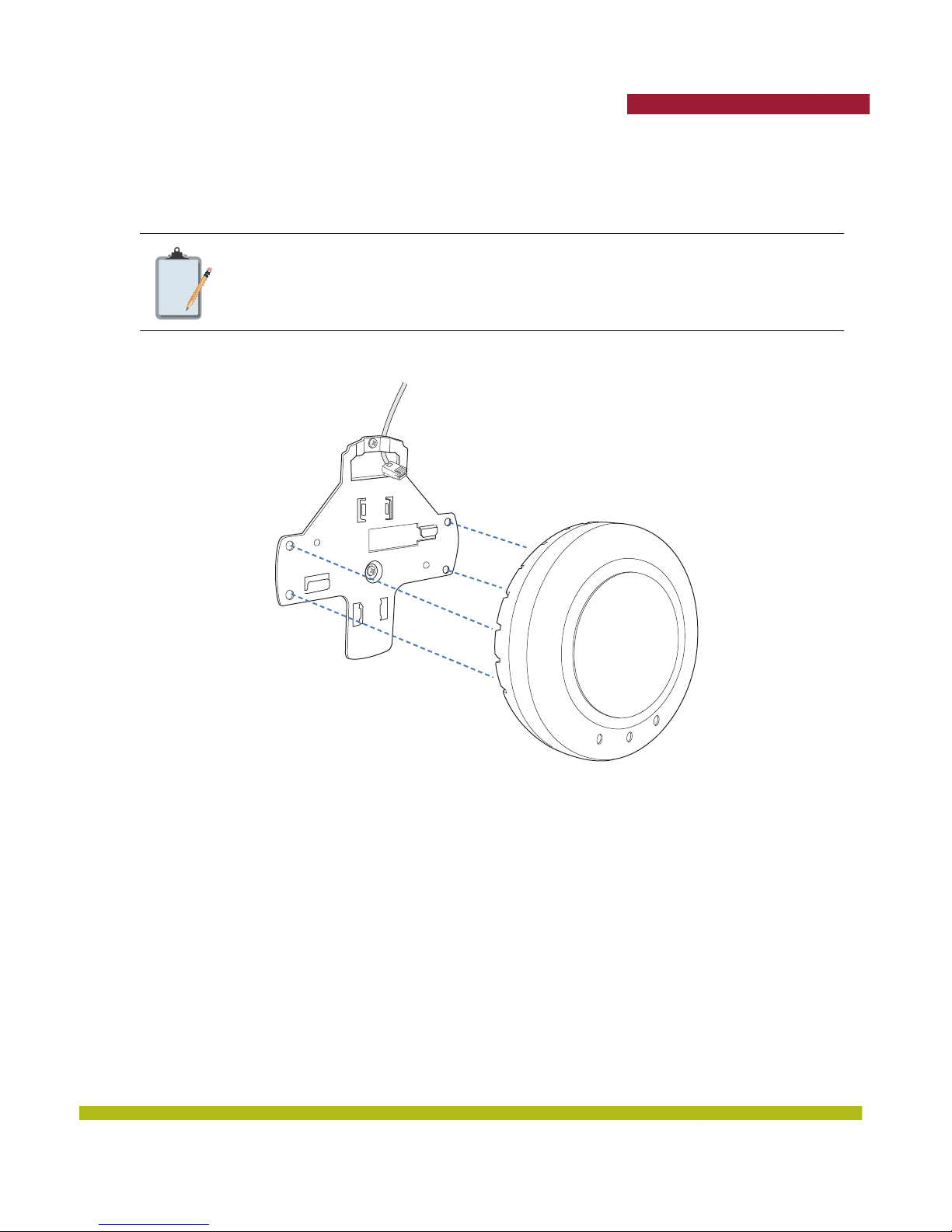
5. As shown in Figure 1–26, feed the Cat 5 cable through the port connector opening and align the
universal mounting bracket over the drywall anchors so that the two screw holes in the bracket
face the drywall anchors.
30
Indoor Mobility Point™ Quick Start Guide
Page 31
Trapeze Networks
6. Insert the #6 sheet metal screws into the screw holes, and tighten them to secure the universal
mounting bracket to the wall or ceiling.
(If you routed the Cat 5 cable through a hole in the wall or ceiling, insert the screw into the center
screw hole only.)
Do not insert screws in the four holes on the edges of the bracket. (These are the holes
Note:
indicated by the dashed lines in Figure 1–26.) The MP fits into these holes. They are
not screw holes.
7. Insert the Cat 5 cable into the connector.
8. Install the Kensington lock, if you plan to use one.
a. Loop the Kensington lock cable around an object that cannot be moved or damaged by a person
pulling on the cable.
b. Insert the key into the Kensington lock.
c. Insert the Kensington lock into the security slot on the MP.
d. Rotate the key right or left to secure the lock to the MP.
e. Pull on the lock to verify that it is secured to the MP.
f. Remove the key.
Figure 1–26. Steps 5 and 6—Bracket Placement on Solid Wall or Ceiling
Indoor Mobility Point™ Quick Start Guide
31
Page 32
Trapeze Networks
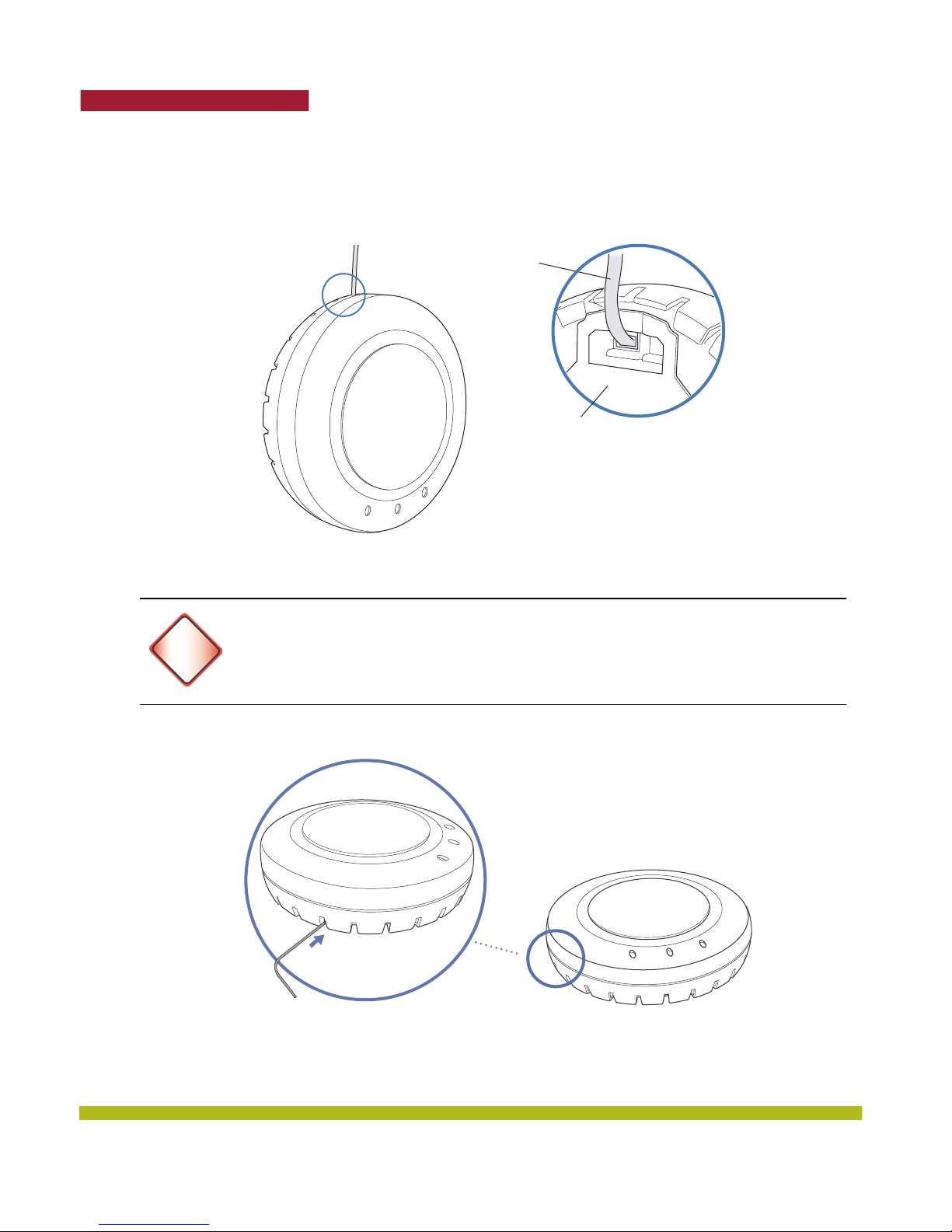
9. As shown in Figure 1–27, place the MP on the bracket, making sure to remove any slack that
occurs in the cable between the bracket and the MP.
Cable
Universal mounting bracket
10. Lock the MP onto the bracket by inserting the lock/unlock tool into the Lock hole on the MP as
shown below.
To prevent possible damage to the MP, make sure the device is fully locked onto the
bracket before releasing it.
Warning!
Figure 1–27. Step 8—Cable Placement
32
Figure 1–28. Step 9—Locking the Bracket
Lock
11. To ensure that the MP is fully locked onto the bracket, gently pull on the MP and attempt to rotate
it from side to side.
Indoor Mobility Point™ Quick Start Guide
Page 33
Trapeze Networks
If the MP comes off the bracket, relock the device onto the bracket as described in step 10 on
page 32.
12. If the MP requires an external antenna, install and connect the antenna.
Tabletop Installation
1. Reverse the universal mounting bracket:
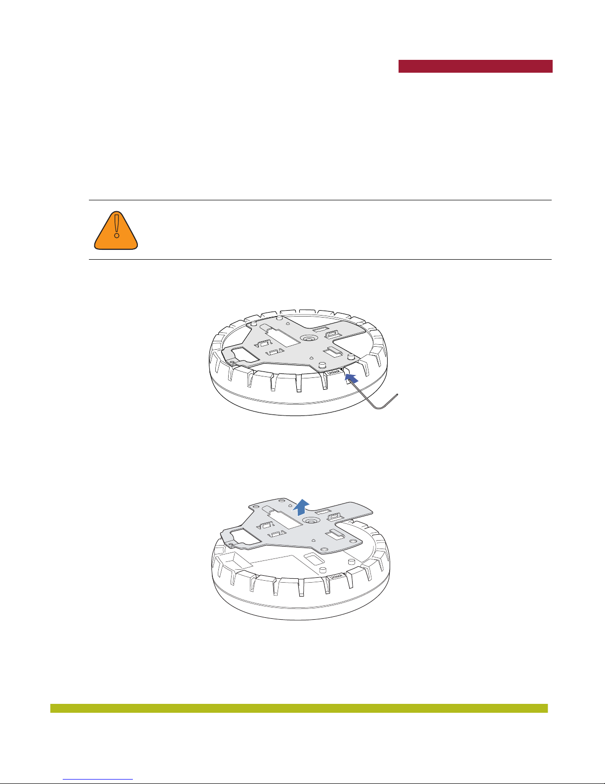
a. Unlock the universal mounting bracket from the MP by inserting the lock/unlock tool into the
Unlock hole on the MP as shown in below.
Use the lock/unlock tool to unlock the MP. Do not use a screwdriver because it may cause
damage to the MP lock mechanism or electronic components. Do not use excessive force
!
Caution
when inserting a tool into the Unlock or Lock hole.
Figure 1–29. Step 1a—Unlocking the Bracket
b. Remove the bracket as shown in Figure 1–30 below.
Figure 1–30. Step 1b—Removing the Bracket
Indoor Mobility Point™ Quick Start Guide
33
Page 34
Trapeze Networks
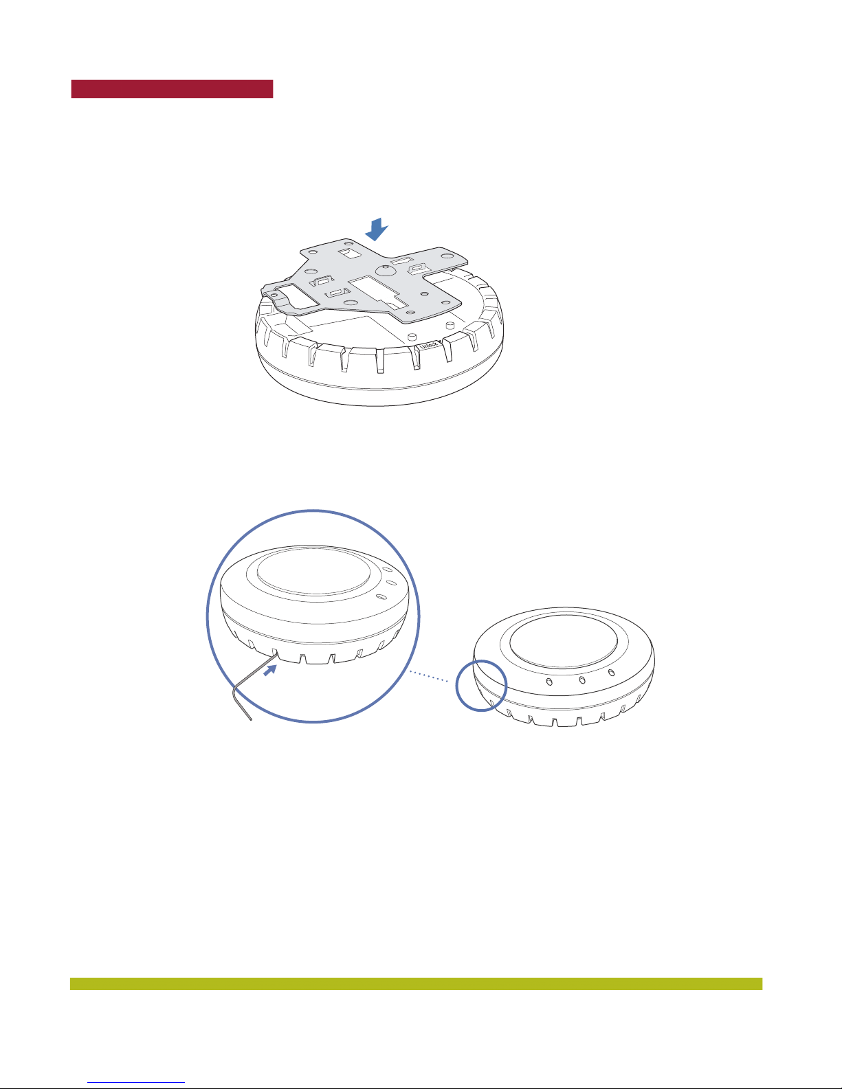
c. Turn over the universal mounting bracket, then align the bracket over the cable ports and the
four mounting posts as shown in Figure 1–31 below.
d. Once the bracket is fully seated, lock the bracket onto the MP by inserting the lock/unlock tool
into the Lock hole on the MP as shown in below.
Figure 1–32. Step 1d—Locking the Bracket
Figure 1–31. Step 1c—Turning Over the Bracket
Lock
2. Insert the Cat 5 cable into the connector.
3. Install the Kensington lock, if you plan to use one.
a. Loop the Kensington lock cable around an object that cannot be moved or damaged by a person
pulling on the cable.
b. Insert the key into the Kensington lock.
c. Insert the Kensington lock into the security slot on the MP.
d. Rotate the key right or left to secure the lock to the MP.
e. Pull on the lock to verify that it is secured to the MP.
f. Remove the key.
34
Indoor Mobility Point™ Quick Start Guide
Page 35
Trapeze Networks
4. Place the MP in the desired location on the table.
5. If the MP requires an external antenna, install and connect the antenna.
Connecting an MP to an External Antenna
Each radio in an Indoor MP can use an optional Trapeze external antenna. To mount the antenna, see
the instructions that come with the antenna.
To connect a mounted external antenna to an MP:
1. Attach the exterior antenna cable that is shipped with the antenna to the MP external antenna
connector.
Both connectors are labeled to indicate the radio type. The MP has RP-SMA connectors for
attachment to the 802.11b/g antenna and to the 802.11a antenna.
The external connectors on the MP are labeled: 11B/G and 11A (excluding the
MP-522E which has numbered ports only). Each connector is a RP-SMA connector.
!
Caution
Note:
Make sure you attach the antenna to the correct connector.
If the MP is installed in a Trapeze Networks outdoor MP enclosure, attach the
antenna cable to the lightning surge arrestor (if installed) or the RP-SMA bulkhead
connector on the enclosure.
2. Attach the other end of the antenna cable to the antenna.
Indoor Mobility Point™ Quick Start Guide
35
Page 36

Trapeze Networks
Installing an Indoor MP-522E
The MP-522E installation steps for ceiling or wall mount are the same as the MP-422/432/522 except
that you must install and orient the four antennas on the MP before supplying power to the unit. The
MP-522E has no internal antennas and requires antennas for all types of operation.Once the MP is
installed on either the wall or ceiling with antennas attached you can switch between Radio 1 and 2
using the CLI command “set ap # radio x mode disable.”
Always install the four MP-522E antennas before supplying power to the MP. Failure to
do so can cause damage to the unit.
Warning!
The tested/certified antennas are equipped with Reverse-SMA or N-type jacks.
This device and its antenna(s) must not be co-located or operated in conjunction with
any other antenna or transmitter.
The external connectors on the MP-522E are labeled 1, 2, 3, 6 on the housing. Each
connector is a RP-SMA connector. Make sure you attach the antenna to the correct
connector.
For products available in the USA/Canada market, only channel 1~11 can be operated.
Selection of other channels is not possible.
This device is going to be operated in 5.15~5.25GHz frequency range, it is restricted in
indoor environment only.
36
Indoor Mobility Point™ Quick Start Guide
Page 37
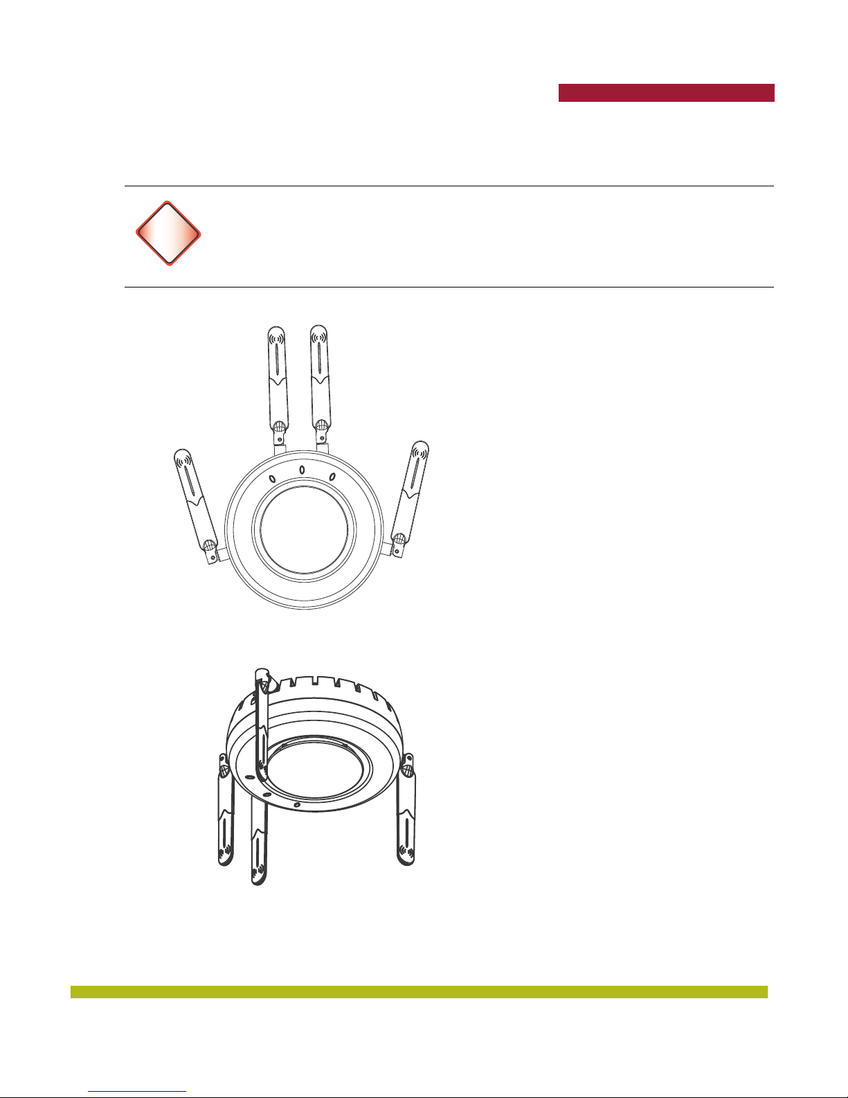
MP-522E Installation Antenna Orientation
Adjust the MP-522E antennas as shown below for optimal polarization.
Always turn the paddle antenna clockwise while adjusting the antenna orientation in
order to prevent loosening of the connector.
Warning!
Wall Mount
Trapeze Networks
Radio port 2
11B/G
Ceiling Mount
Radio port 3
11A
Radio port 6
11A
Radio port 1
11B/G
Indoor Mobility Point™ Quick Start Guide
37
Page 38
Trapeze Networks
Connecting an MP to an MX
You can connect an MP directly to an MX or indirectly to the MX through an intermediate Layer 2 or
Layer 3 network. If you are connecting the MP directly to an MX, use the following procedure to
insert the cable into the MX and verify the link.
You can use the CLI or RingMaster to configure an MP connection. If you are installing the MP as a
Mesh AP in a WLAN Mesh or wireless bridge configuration, you must configure the MP connection
before deploying the MP in the final location. (See the Mobility System Software Configuration Guide
or the Configuration Guide.)
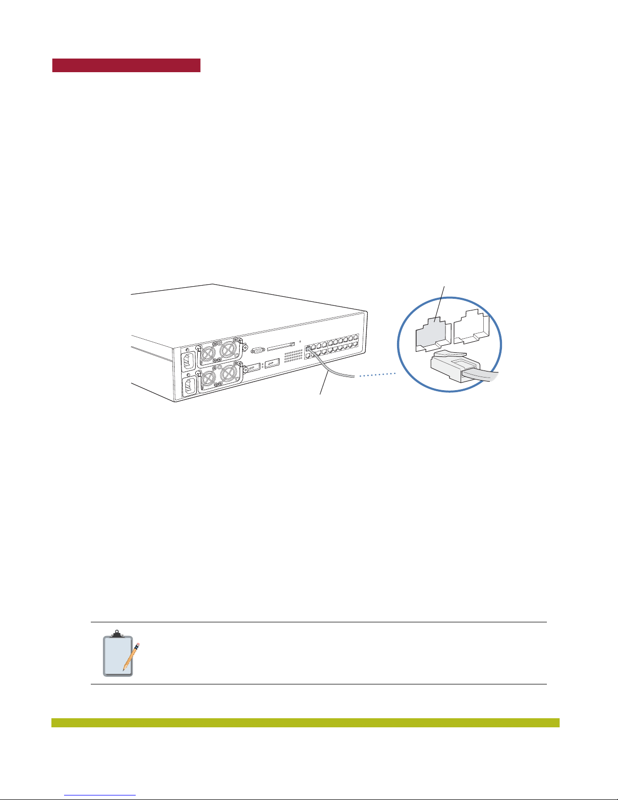
Figure 1–33 below shows how to insert a Cat 5 cable into 10/100 Ethernet port on an MX. Refer to this
figure as you perform the procedure.
Figure 1–33. 10/100 Cat 5 Cable Installation
1. Insert a Cat 5 cable with a standard RJ-45 connector as shown in Figure 1–33. For connection to
an MP, use a straight-through cable.
2. When the link is activated, observe the MP LED for the port on the MX:
Configuring the MP
To configure the channels, power settings, and other MP parameters, see the following:
❑ Trapeze Mobility System Software Quick Start Guide
❑ “Configuring MP Access Points” chapter in the Trapeze Mobility System Software Configuration
Guide
obility Exchange
M
MX-20
Ethernet cable
(Cat 5 cable)
Ethernet port
MP, switch, server
or other device
External Antenna Connectors
The Indoor MPs (except for the MP-82 and MP-432) have connectors for attaching optional external
antennas. Table 1– 3 below lists the Trapeze-supported external antenna models.
The numbers in parentheses in the table below are the numbers that appear on the
Note:
38
back of an 802.11a antenna reflector plate. To verify an 802.11a external antenna
model number, look for the number in parentheses
Indoor Mobility Point™ Quick Start Guide
Page 39
Trapeze Networks
The MP-82 has three external antenna connectors, but external antennas are not
Note:
Table 1– 3. Trapeze External Antenna Models MP-422 Only
supported at this time.
Model Type Gain
Beamwidth
Horizontal Vertical
802.11a 8 dBi 360° 15°
ANT-7360
802.11b/g 6 dBi 360° 25°
802.11a 8 dBi 360° 15°
ANT-7360-OUT
802.11b/g 6 dBi 360° 22°
ANT-5060 (ASTN6S)
ANT-5120 (ASTN6T)
ANT-5180 (ASTN6H)
ANT-1060
ANT-1120
ANT-1180
802.11a 14.5 dBi 60° 14°
802.11a 12.5 dBi 120° 14°
802.11a 10.8 dBi 180° 14°
802.11b/g 10 dBi 60° 65°
802.11b/g 7 dBi 120° 60°
802.11b/g 6 dBi 180° 40°
The Indoor MP radios are certified for use only with these external antennas.
Note:
39
© 2010 Trapeze Networks, Inc. All rights reserved. Trapeze Networks, the Trapeze Networks logo
design, Trapeze Smart Mobile, Trapeze Networks Mobility System Software, RingMaster,
Mobility System, Mobility Exchange, Mobility Point, SafetyNet, MX, and MP are registered
trademarks and/or registered service marks of Trapeze Networks, Inc. Trapeze, Smart Mobile,
Mobility System Software, Mobility Domain, SmartPass, NonStop Wireless, Medical Grade
Mobility and Wireless Without Limits are trademarks and/or service marks of Trapeze
Networks, Inc. All other products and services are trademarks, registered trademarks, service
marks, or registered service marks of their respective owners.
All statements, specifications, recommendations, and technical information are current or
planned as of the publication of this document. They are reliable as of the time of this writing
and are presented without warranty of any kind, expressed or implied. In an effort to
continuously improve the product and add features, Trapeze Networks reserves the right to
change any specifications contained in this document without prior notice of any kind.
 Loading...