

TRANZSPORTER TP250, TP40 Owner's Manual
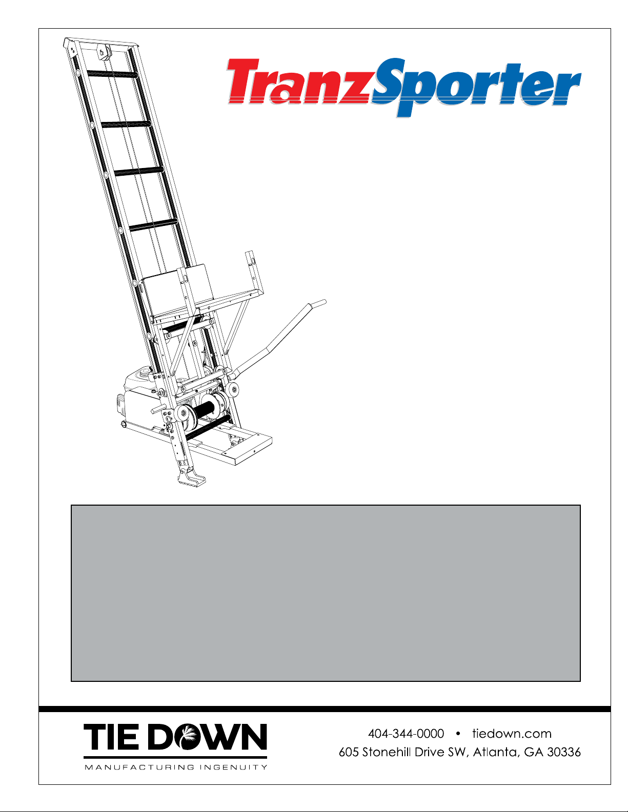
Platform Hoist
Owners Manual
Updated: 4/8/19
TP250
250 lb. Capacity
TP400
400 lb. Capacity
For the Most Up to Date Information and
Instructions, Visit the TranzSporter Web Site
at www.tranzsporter.com.
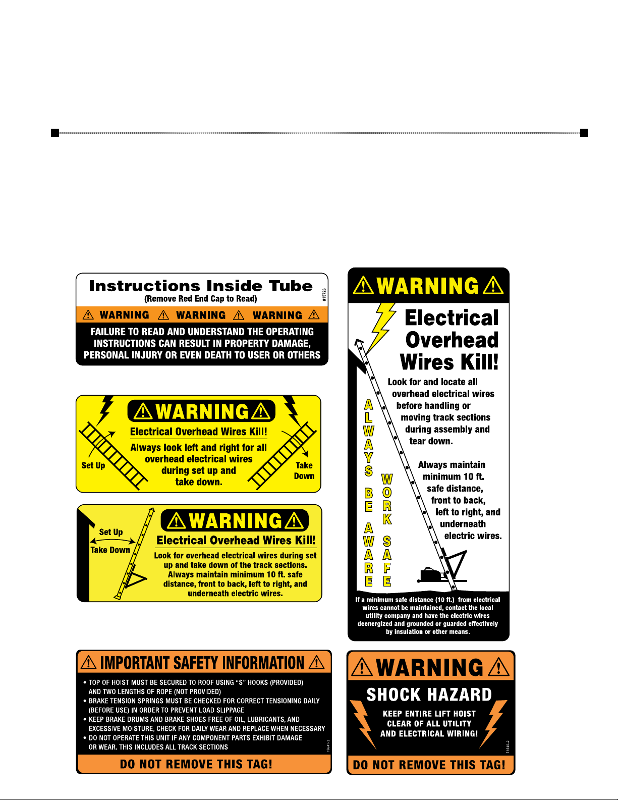
CRITICAL SAFETY INFORMATION: The greatest exposure to serious bodily injury and or death may occur when the
Tranzsporter track sections are located within 10 ft. (left or right or underneath) overhead electric power lines. If a minimum
safe distance (10 ft.) from electrical wires cannot be maintained, contact the local utility company and have the electric wire
unenergized and grounded or guarded effectively by insulating or other means.
A COMPETENT PERSON must be present during any set up, during any repositioning, and during any tear down operations
of the Transporter track sections when the Transporter is to be located near electric power lines. A COMPETENT PERSON must
read and understand the Owners Manual for set up, operating instructions, and tear down instructions in order to insure that
all personnel authorized to set up, operate, and tear down the Transporter are made aware of ALL SAFETY WARNINGS as well
as the operating instructions. ALWAYS USE APPROVED ROOF TOP fall protection when setting up, operating, and taking down
the Tranzsporter Hoist.
Instructions #08238 Rev. 4/8/19
E1399
Congratulations on your Purchase of the TranzSporter Lift Hoist.
The TranzSporter Lift Hoist was designed to provide safe and continuous operation.
Features Include...
• Collapsible carriage comes with track cam followers for better tracking and handling.
• Aluminum deck and flap for lighter weight and longer life.
• Rolled goods/plywood brackets comes with unit and pins into carriage.
• Two safety nylon tie down straps for use with plywood/sheet panels.
• Motor base is manufactured using laser cut steel tubing for extra strength and durability.
• Belt guard and foot pedal are detailed with aluminum diamond plate.
• Dual versatile brake may be operated from either side of platform hoist.
• An additional handle may be used to engage the carriage instead of using the foot pedal
(#48468 handle kit sold separately).
• A 4 ft. heavy duty aluminum base track utilizes laser cut steel tube support plates for job site toughness.
• Base track features large cast aluminum feet for added stability.
• Dual band brake system for smoother stops.
• Amber colored carriage bumpers to protect against damage and wear from repeated lowering
(can be rotated).
• Oversized clip pins for fast and simple removal of quick change cable drum and belt replacement.
Your new Tranzsporter Lift Hoist is shipped in 3 boxes and one track section bundle
Base Section
Includes: 4ft. Track Base,
Cable Drum, Top Cap and
Brake Handle.
Carriage Base
Includes: Collapsible
Carriage and Plywood
Attachments.
Engine/Motor Base
Includes: Lifan, Honda engine or
Electric motor, engine instructions,
warranties and operation manual
(in steel tube).
Track Sections
Includes: 3 - 8ft. track sections,
6 splice plates and mounting
hardware (installed).
2
Welcome & Box Continent

General Safety Instructions:
In order to set up and operate the Tranzsporter ladder hoist safely in and around ELECTRIC POWER
LINES and be compliant with OSHA Regulations 1926.416(a) , the following must be ascertained
prior to setting up the Tranzsporter each time for the Protection of Employees .
1926.416 (a)(1): No employer shall permit an employee to work in such proximity to any part of an
electric power circuit that the employee could contact the electric power circuit in the course
of work, unless the employee is protected against electric shock by unenergized the circuit and
grounding it or by guarding it efficiently by insulation or other means.
1926.416 (a)(3): Before work is begun the employer shall ascertain by inquiry or direct observation,
or by instruments, whether any part of an energized electric power circuit, exposed or concealed,
is so located that the performance of the work may bring any person, tool, or machine into physical
or electrical contact with the electric power circuit. The employer shall post and maintain proper
warning signs where such a circuit exists. The employer shall advise employees of the location of
such lines, the hazards involved, and the protection to be taken.
1926.502 (a) (2): Employers shall provide and install all fall protection systems required by this
subpart for an employee, and shall comply with all other pertinent requirements of this subpart
before the employee begins the work that necessitates the fall protection.
THE FOLLOWING VIDEO LINKS SHOULD BE THROUGHLY REVIEWED AND UNDERSTOOD PRIOR TO
SETTING UP AND OPERATING, DISMANTLING THE TRANZSPORTER LADDER HOIST
TranzSporter Collapsible Carriage Platform Hoist:
https://www.youtube.com/watch?v=-jF4uT0YcB4
OSHA Hazards: Fall Protection:
WxTV will set its sights on the number one cause of fatalities on the job site, falls, and what OSHA
requirements you need to know to protect yourself. Tune in to get the goods on the gear to stay safe and
alive.
https://www.youtube.com/watch?v=z62qFhfT3a4
OSHA: Fall Protection Training:
https://www.youtube.com/watch?v=I4XW926vpkA
OSHA Stairway and Ladder Safety Quiz 2 (15 Questions With Fully Answers):
https://www.youtube.com/watch?v=Pj4t7QpQXqs
Standing on the Edge
This video graphically shows how workplace injuries and fatalities can be shocking and life-changing.
https://www.youtube.com/watch?v=C4S0rAZypzY
Safety Warnings
3

WARNING:
• DO NOT OPERATE THIS EQUIPMENT IF ANY UNSAFE CONDITIONS EXIST OR OCCUR DURING OPERATION.
• KEEP TRACK SECTIONS MINIMUM 10 FT. CLEAR OF ALL ELECTRICAL WIRES AND EQUIPMENT.
• BE AWARE OF OVERHEAD OBJECTS.
• NEVER USE TRACK SECTIONS AS A LADDER.
• NEVER OPERATE HOIST WITH A HUMAN ON PLATFORM.
• NEVER STAND UNDER PLATFORM WHEN LOWERING.
• NEVER USE INDOORS OR IN AN AREA WITH POOR VENTILATION (ELECTRIC MODEL IS EXCLUDED).
• NEVER USE HOIST TO LOWER MATERIAL.
• ALWAYS USE APPROVED ROOF TOP FALL PROTECTION WHEN SETTING UP, OPERATING, AND TAKING
DOWN THE TRANZSPORTER HOIST.
User Responsibilities
PERFORM THE FOLLOWING AT THE START AND END OF THE WORK DAY AND AFTER 4 HOURS
OF OPERATION DURING THE DAY:
• Check oil level in engine and fill according to manufacturer’s specifications.
• Check cable for smooth operation and for signs of wear.
• Check for loose bolts and tighten according to specifications.
• Check track sections and all other moving parts for excessive wear or fatigue.
• Check general condition of equipment.
• Check and confirm operator’s understanding of the proper operation for this equipment.
• When using the electric motor; check extension cords and connections for wear or damage.
• Check brake parts regularly for wear or damage.
• Check cable drum bearings, they should run smoothly when the brake is released. If there is any noise
or if the cable drum does not spin freely, replace drum bearings immediately.
• Check for minimal clearance between outer track cam followers.
General Safety Instructions:
1. Transport and handle your TranzSporter Hoist with care.
2. Unpack the TranzSporter carefully and inspect for any damage that may occur during transportation.
DO NOT USE THE HOIST IF ANY PART IS DAMAGED.
3. Please observe all safety and warning labels attached to the hoist.
4. Use only replacement parts furnished by the manufacturer.
5. Always keep the area around the base section of the TranzSporter Hoist clear to help prevent slipping,
tripping or falling against the hoist.
6. DO NOT ALLOW ANYONE TO OPERATE THE TRANZSPORTER HOIST WHO HAS NOT BEEN THOROUGHLY
AND PROPERLY TRAINED IN THE CORRECT OPERATION AND USE OF THIS HOIST.
7. This hoist is manufactured to lift materials only. Do not use the TranzSporter Hoist for the purpose of
transporting personnel from one level to another.
8. Do not climb the TP-Series hoist or use as a personnel ladder.
9. DO NOT OVERLOAD:
Maximum lifting capacity for the TP250 is 250 lbs. with a load capacity of 230 lbs.
Maximum lifting capacity for the TP400 is 400 lbs. with a load capacity of 380 lbs.
10. Keep hands, feet and other body parts as well as clothing away from the track sections and moving or
rotating parts of the TranzSporter Hoist when starting the engine or when operating the hoist.
11. Do not allow any persons to walk or work under or near the TranzSporter Hoist while in operation.
12. Do not use this hoist to transport hot asphalt or any other hot molten substance from one elevation
to another.
4
Warnings and General Safety Instructions
General Safety Instructions (Continued):
13. Store all parts of the TranzSporter Hoist in such a fashion as not to damage any of the components.
14. Do not operate indoors or in an area with poor ventilation. Electric motor model is excluded.
15. Never lift sheet or panel goods without the use of the plywood brackets and the tie down straps provided
(See page 17).
CAUTION: Please read the safety warnings and Instructions contained in this manual before operating the
lift hoist. Failure to obey the warnings contained herein could result in damage to the equipment, personal
injury, or death, this information should not be a substitute for routine accident prevention, but rather an
addition to routine accident prevention.
Warning labels are attached to the TP250/400 and are weather resistant. If you notice any of these decal’s
missing from your hoist, please contact TIE DOWN ENGINEERING for a replacement label.
5
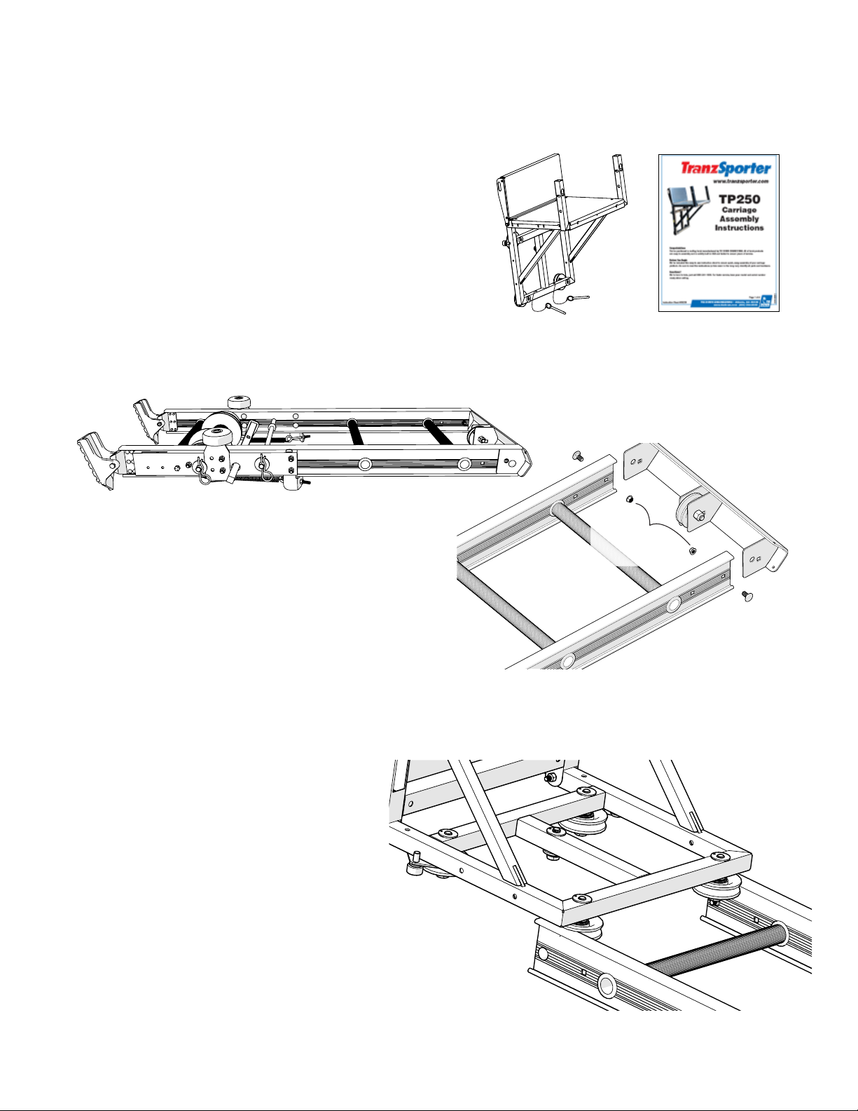
Assembly Instructions for the TP250 Hoist
Instructions for the TP400 Hoist skip to page 8
Step 1
If you have not already assembled the carriage assembly,
Stop Now. You must first assemble the carriage,
follow the assembly instructions included in the #2 Box “Collapsible Carriage & Plywood Attachments”.
Step 2
Remove base section from its box and place on a
clean floor or assembly area. Remove the top cap
with a 7/16” wrench (one bolt/nut on each side).
Step 3
Starting at the top of the track section slide carriage
assembly onto track section so that the four rollers
connect to the top rail of the track section.
Remove
3/8” Keeper
Nuts
6
TP250 Assembly Instructions
Step 4
Front
Back
“Roll”carriage assembly onto the base. At this
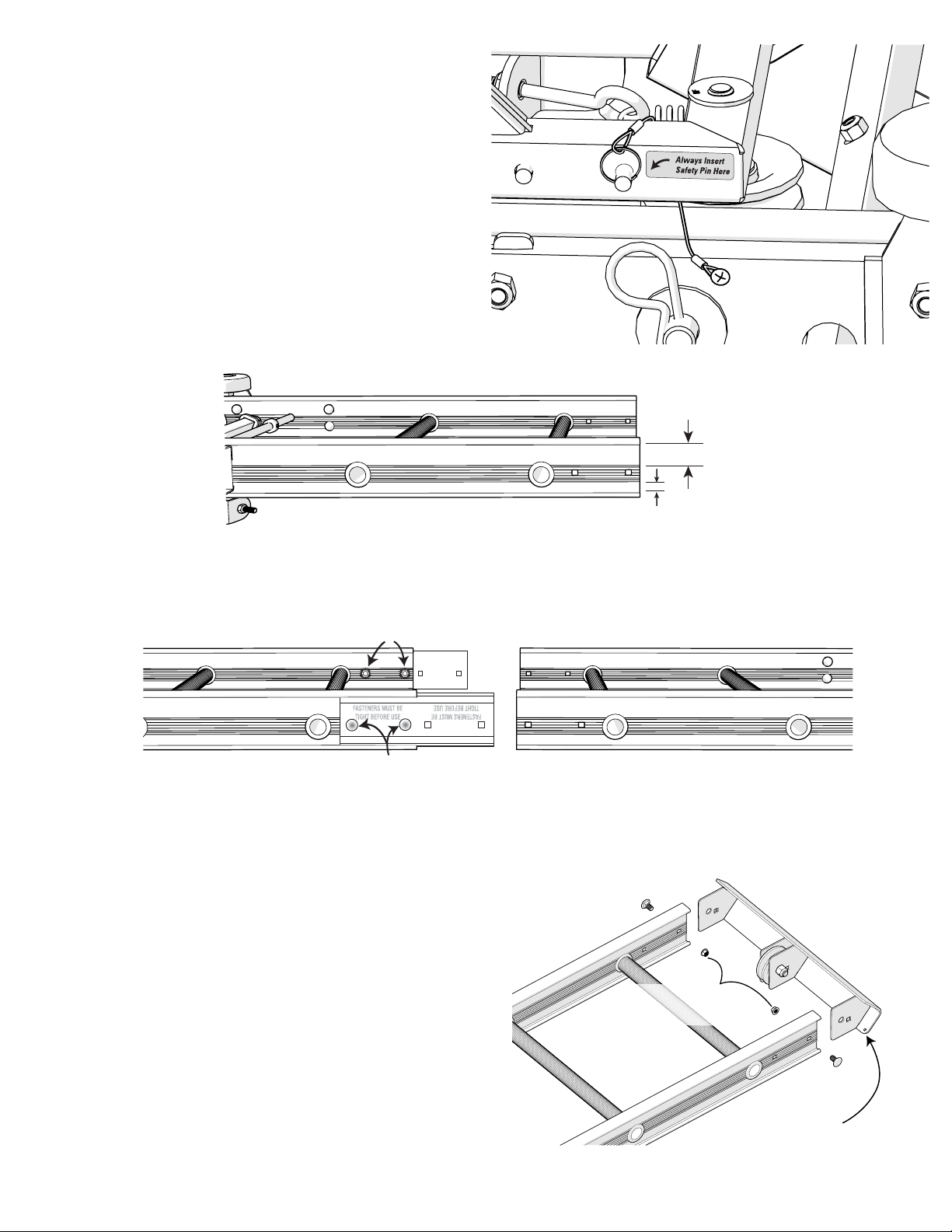
time lock the base in place using the Safety Pin
as shown. Be sure to loop the lanyard over the
carriage base as shown.
Important: Always check for wear or damage
to the safety pin cable/pull ring assembly.
Failure to replace damaged safety pin
cable assembly may cause damage or
personal injury.
Front
Back
Step 5
Lay one track section on a flat floor with the “front” side up. This is determined by the space between the
track cross bar and the track section edge as shown above.
3/8” Keeper Nuts
3/8” x 3/4” Carriage Bolts
Step 6
Attach splice plates to the bottom section of the track. Splice plates are mounted on the outside track
section. Slide the top section track into the groves on the inside track section, attach with 2 nuts and bolts
per side (See above). Ensure bolts and nuts are torqued to 30 ft.-lbs.
NOTE: DO NOT SUBSTITUTE NUTS AND BOLTS
Use 3/8”x 3/4” carriage bolts and 3/8” keeper nuts
(lock washer and nut combined).
Replace
Top Cap
Step 7
Reattach the top cap to the end of the last section of
track section you intend to use. Assemble with two
3/8”x 3/4” carriage bolts with keeper nuts provided.
Make sure that the top cap end slides into the outside
of the track section (shown right). Ensure bolts and
nuts are torqued to 30 ft.-lbs.
Important: Make sure the mounting hole for the “S”
hook is located on the back of the hoist assembly.
Replace & Tighten
3/8” Keeper Nuts
3/8”x 3/4”
Carriage Bolts
“S” Hook Mount
TP250 Assembly Instructions
7
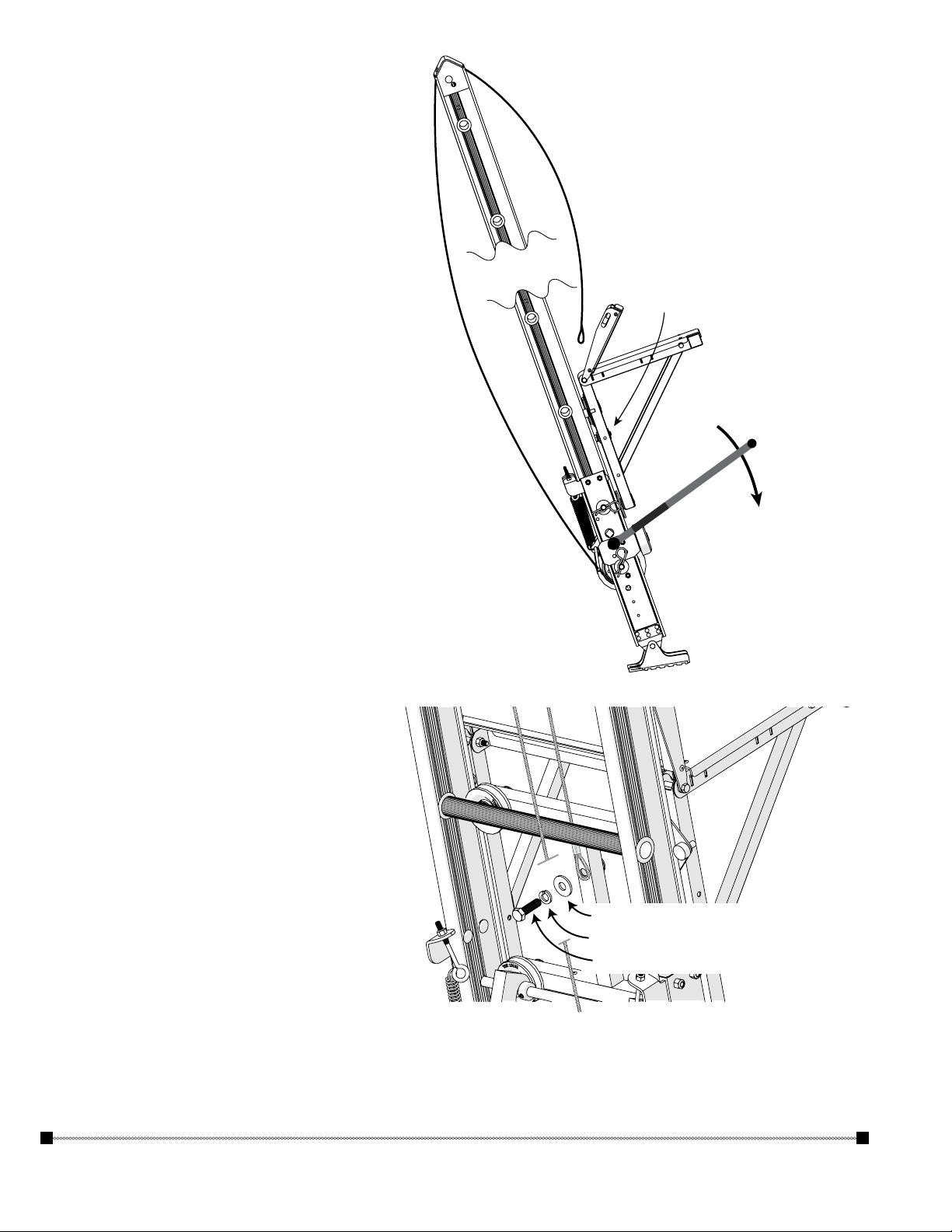
Feed end cable
Step 8
Turn the hoist on its side, and working from the
back, remove the end of the cable from the drum
(shown right). It helps to attach the brake handle,
use the brake handle to release the brake drum.
The cable will then easily un-spool. Staying on
the outside (back) of the base section and track
section, take the cable to the top of the last track
section where the top cap pulley is attached.
Step 9
Feed the cable end through the pulley as shown
above , and down the front side of the track
section to the back of the carriage assembly.
through pully
Attach cable to
the back of the
carriage (cross bar)
Step 10
Attach cable to the carriage assembly, pass
bolt through lock washer, washer and
cable end/eye. Tighten bolt as shown right.
Attach brake handle
and pull downward
to release cabel drum
Unwind cable
from the back
1/2” Washer
1/2” Lock Washer
1/2”x 1-3/4” Bolt
You have completed the assembly of the TP250 Hoist
Skip to page 11 for Operation and Placement Instructions.
8
TP250 Assembly Instructions
 Loading...