

Page 1

-5A
Tranzeo TR-5A Series
User Guide
Covers the following models:
TR-5a-19,TR-5a-20, TR-5a-21,
TR-5a-24, TR-5a-N, TR-5Plus-24,
TR-5Plus-N, TR-500, TR-5amp-24,
TR-5amp-N, TR-SL5-16, TR-SL5-N
Revision: 2.1
Firmware: 5.0.2
Date: 12/2/10
TRANZEO TR
Page 2

Document Revisions:
Version 1.0 May 15, 2006
Version 1.1 May 30, 2006
Version 1.2 September 8, 2006
Version 1.3 January 9, 2008
Version 1.4 January 28, 2008
Version 2.0 November 10, 2009
Version 2.1 February 12, 2010
Tranzeo Wireless Technologies Inc.
19473 Fraser Way
Pitt Meadows, BC
Canada V3Y 2V4
Toll Free Number: 1.866.872.6936
Technical Support: 1.888.460.6366 General Inquiries: [email protected]
Local Number: 1.604.460.6002 Sales: [email protected]
Fax Number: 1.604.460.6005 Technical Support: [email protected]
iiiiii
This document is intended for Public Distribution 19473 Fraser Way,
Pitt Meadows, B.C. Canada V3Y 2V4
ii
Page 3

Tranzeo Wireless Technologies
Safety Information
Safety Information
FCC Compliance
This device has been tested and found to comply with the limits for a Class B digital device
pursuant to Part 15 of the FCC rules. These limits are designed to provide reasonable
protection against harmful interference when the device is operated in a residential
environment. This device generates, uses, and can radiate radio frequency energy. If not
installed and used in accordance with the user guide, may cause harmful interference to radio
communication. In case of harmful interference, the users will be required to correct the
interference at their own expense.
The users should not modify or change this device without written approval from Tranzeo
Wireless. Modification will void warranty and authority to use the device.
For safety reasons, people should not work in a situation where RF exposure limits could be
exceeded. To prevent this situation, the users should consider the following rules:
Install the antenna so that there is a minimum of 100 cm (39.37 in) of distance between
the antenna and people. The TR-5amp series requires 268 cm (105.5 in) between the
antenna and people.
Do not turn on power to the device while installing the antenna.
Do not connect the antenna while the device is in operation.
Do not collocate or operate the antenna used with the device in conjunction with any
other antenna or transmitter.
This device has been designed to operate with the antennas listed below, and having a
maximum gain of 32 dB. Antenna types not included in this list or antennas of a type
listed having a gain greater than the value listed are strictly prohibited for use with this
device. The required antenna impedance is 50 ohms.
TR-GD58-26 – 5.8 GHz 26 dBi Grid antenna
TR-HTQ-5.8-12 – 5.8 GHz 12 dBi Omni antenna
TR-58V-60-17 – 5.8 GHz 17 dBi Vertical Sector antenna
TR-58H-90-16 – 5.8 GHz 16 dBi Horizontal Sector antenna
TR-5.8-32db-ant—5.8 GHz 32dBi Dish antenna
In order to ensure compliance with local regulations, the installer MUST enter the
antenna gain at the time of installation. See Chapter 3: Wireless Settings, for details.
Industry Canada Compliance
Operation of this device is subject to the following two conditions: (1) this device may not
cause interference, and (2) this device must accept any interference, including interference
that may cause undesired operation of the device.
TR-5A Series
Pitt Meadows, B.C. Canada V3Y 2V4
iiiiiiiii
This document is intended for Public Distribution
19473 Fraser Way,
iii
Page 4

!
Tranzeo Wireless Technologies
Safety Information
Safety Instructions
You must read and understand the following safety instructions before installing the device:
This antenna‘s grounding system must be installed according to Articles 810-15, 810
-20, 810-21 of the National Electric Code, ANSI/NFPA No. 70-1993. If you have any
questions or doubts about your antenna‘s grounding system, contact a local licensed
electrician.
Never attach the grounding wire while the device is powered.
If the ground is to be attached to an existing electrical circuit, turn off the circuit before
attaching the wire.
Use the Tranzeo Power over Ethernet (POE) adapter only with approved Tranzeo
models.
Never install radio equipment, surge suppressors or lightning protection during a storm.
Lightning Protection
The key to lightning protection is to provide a harmless route for lightning to reach ground.
The system should not be designed to attract lightning, nor can it repel lightning. National,
state and local codes are designed to protect life, limb, and property, and must always be
obeyed. When in doubt, consult local and national electrical codes or contact an electrician or
professional trained in the design of grounding systems.
Professional Installation Required
The product requires professional installation. Professional installers ensure that the
equipment is installed following local regulations and safety codes.
TR-5A Series
Pitt Meadows, B.C. Canada V3Y 2V4
iviviv
This document is intended for Public Distribution
19473 Fraser Way,
iv
Page 5

Tranzeo Wireless Technologies
Table of Contents
Table of Contents
Chapter 1: Overview ........................................................................ 1-1
Introduction ...................................................................................................... 1-1
Product Kit........................................................................................................ 1-1
Product Description .......................................................................................... 1-1
LED Panel Indicators ................................................................................... 1-2
Chapter 2: Hardware Installation ...................................................... 2-1
Getting Ready ................................................................................................... 2-1
Tools Required ............................................................................................. 2-1
Site Selection ............................................................................................... 2-1
Polarity ......................................................................................................... 2-2
Power Supply ............................................................................................... 2-2
Installing the Ethernet Cable ............................................................................ 2-3
Mounting the Radio .......................................................................................... 2-5
Grounding the Antenna .................................................................................... 2-5
Connecting the Radio ....................................................................................... 2-6
Best Practices.................................................................................................... 2-7
Chapter 3: Configuration ................................................................... 3-1
Connecting to the Radio ................................................................................... 3-1
Changing the IP Address - Windows XP .................................................... 3-1
Changing the IP Address Using the Tranzeo Victor Program ..................... 3-2
Login into the Configuration Interface ............................................................. 3-4
Information Page .............................................................................................. 3-5
Setup Menu ....................................................................................................... 3-6
Wireless Settings - Basic Tab, Access Point .............................................. 3-6
Wireless Settings - Basic Tab, Infrastructure Station ................................. 3-8
To operate in PxP mode ............................................................................... 3-10
Wireless Settings - Advanced Tab, Access Point ....................................... 3-11
Wireless Settings - Advanced Tab, Infrastructure (CPE) ........................... 3-12
Administrative Settings - Firmware Tab .................................................... 3-13
Administrative Settings - Import / Export Tab ........................................... 3-14
Administrative Settings - SNMP Tab ......................................................... 3-15
WDS ............................................................................................................ 3-16
Security ........................................................................................................... 3-17
WEP Settings ............................................................................................. 3-17
WPA Settings ............................................................................................. 3-18
TR-5A Series
Pitt Meadows, B.C. Canada V3Y 2V4
vvv
This document is intended for Public Distribution
19473 Fraser Way,
v
Page 6

Tranzeo Wireless Technologies
Access Control ........................................................................................... 3-19
DFS / TPC .................................................................................................. 3-20
Status .............................................................................................................. 3-21
Station List ................................................................................................. 3-21
AP List ....................................................................................................... 3-22
ARP Table ................................................................................................. 3-22
Statistics ..................................................................................................... 3-23
Wireless Performance (CPE Only) ............................................................ 3-25
System Performance .................................................................................. 3-26
Network Configuration ................................................................................... 3-27
Bridge Mode - Static ................................................................................. 3-27
Bridge Mode - DHCP Client .................................................................... 3-28
Router Mode .............................................................................................. 3-29
Router Mode - PPPoE ............................................................................... 3-30
Networking Advanced - Bridge Mode ..................................................... 3-31
Networking Advanced - Router Mode ..................................................... 3-32
DHCP Configuration ................................................................................. 3-33
IP Routing .................................................................................................. 3-34
Shaping and Quality of Service Configuration (QoS) ............................... 3-35
Port Forwarding ......................................................................................... 3-37
IP Filtering ................................................................................................. 3-38
Table of Contents
Appendix A: Grounding and Lightning Protection Information .... A-1
Appendix B: Quality of Service Configuration (QoS) ..................... B-1
Appendix C: Protocol List ................................................................. C-1
Appendix D: Common TCP Ports ..................................................... D-1
Appendix E: Channel Allocations .................................................... E-1
Appendix F: Wiring Standard ........................................................... F-1
Appendix G: Routing Quick Start Guide .......................................... G-1
Appendix H: PxP Install Checklist .................................................... H-1
Appendix I: Glossary of Terms ......................................................... I-1
Appendix J: AutoConfig .................................................................... J-1
TR-5A Series
Pitt Meadows, B.C. Canada V3Y 2V4
vivivi
This document is intended for Public Distribution
19473 Fraser Way,
vi
Page 7

Tranzeo Wireless Technologies
Table of Contents
Appendix K: Tranzeo Electrical Plugs ............................................. K-1
Appendix L: Warranty Terms ............................................................ L-1
Appendix M: How Can We Improve? ............................................... M-1
Appendix N: Notes ............................................................................. N-1
TR-5A Series
Pitt Meadows, B.C. Canada V3Y 2V4
viiviivii
This document is intended for Public Distribution
19473 Fraser Way,
vii
Page 8
Tranzeo Wireless Technologies
Introduction
This next-generation wireless LAN device–the Tranzeo TR-5A series– brings
Ethernet-like performance to the wireless realm. Fully compliant with the
IEEE802.11a standard, the TR-5A series also provides powerful features such as
the Internet-based configuration utility as well as WEP and WPA security.
Product Kit
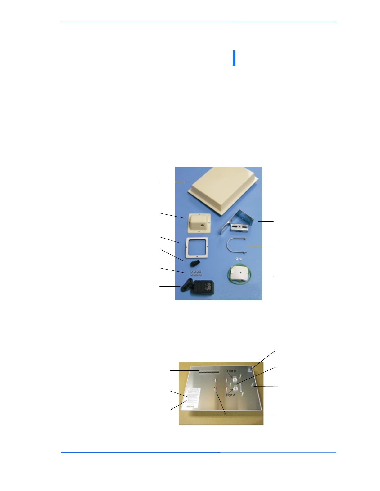
The TR-5A Series product kit contains the items shown below. If any item is
missing or damaged, contact your local dealer for support.
TR-5A Series device x 1
Ethernet boot cover x 1
3/4‖ Strain relief x 1
3/8‖ x 10/32 Kep nuts x 8
Gasket x 1
DC power
adapter x 1
Chapter 1: Overview
Chapter 1: Overview
Mounting bracket x 1
Saddle x 1
U-bolt x 1
with 2 1/2‖ nuts
POE adapter x 1
Product Description
The LEDs, ports and product information are located at the back of the TR-5A
Series radio, as shown in the picture.
LED Panel indicators
Serial number
MAC address
TR-5A Series
Pitt Meadows, B.C. Canada V3Y 2V4
Grounding Lug
Ethernet ports
Studs for the boot
cover
Studs for the
mounting bracket
111
This document is intended for Public Distribution
19473 Fraser Way,
1-1
Page 9
Tranzeo Wireless Technologies
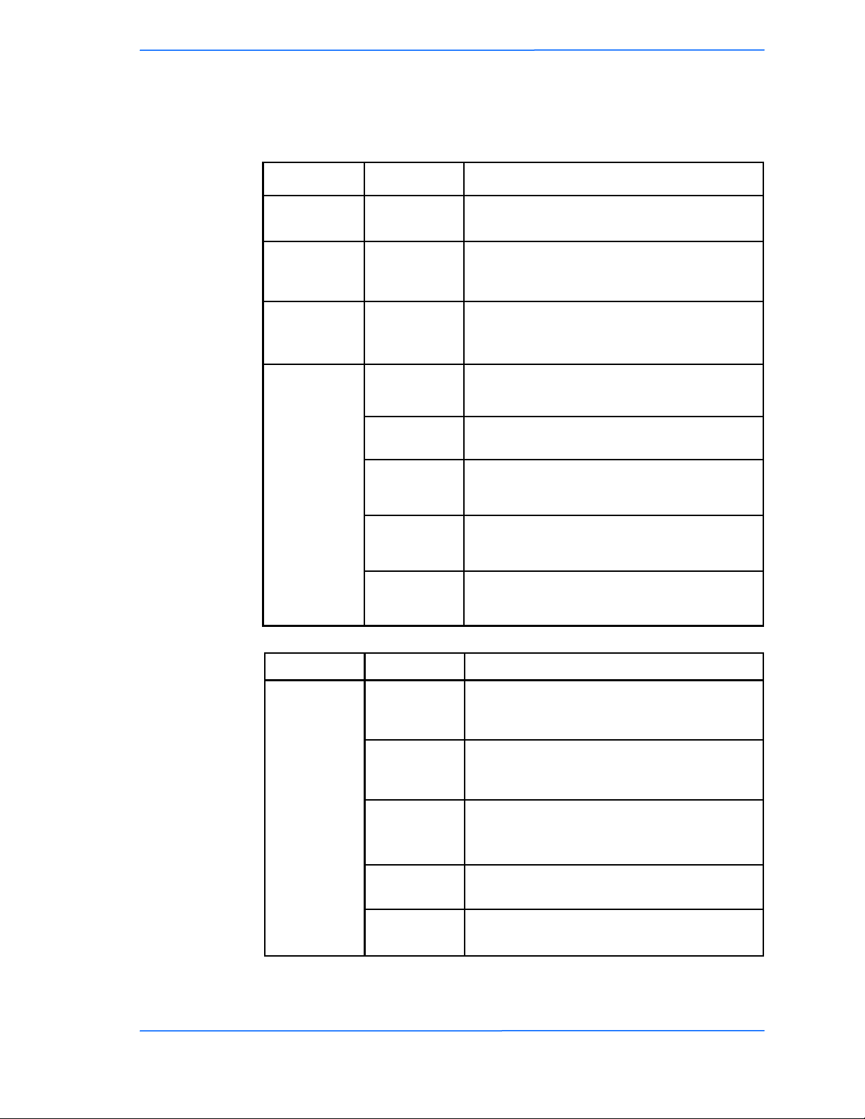
LED Panel Indicators
Chapter 1: Overview
Operational Color Indicators
Power
LAN
● Red
● Green
On: Powered on
Off: No power or LED’s Disabled
On: Ethernet link
Flashing: Ethernet traffic
Off: No Ethernet link
On: Radio link
Radio
● Amber
● Red
Signal
(CPE or PxP
Mode)
In CPE mode
LEDS light up
in sequence
to indicate
signal
strength
based on
Signal -
Noise.
● Amber
● Amber
● Green
● Green
Flashing: Radio activity
Off: No radio link
1 to 10 db above noise
11 to 15 db above noise
16 to 20 db above noise
21 to 30 db above noise
31 or more db above noise
Label Color Indicators
Operational
Info
(AP Mode)
TR-5A Series
Pitt Meadows, B.C. Canada V3Y 2V4
On: WEP/128 enabled
● Red
● Amber
● Amber
● Green
● Green
222
This document is intended for Public Distribution
19473 Fraser Way,
Flashing: WEP/64 enabled
Off: WEP off
On: WPA/AES enabled
Flashing: WPA/TKIP enabled
Off: WPA off
On: 5.8 operation
Off: 5.3 operation
Flashing: 2.4 operation
On: ACL enabled
Off: ACL off
On: WDS enabled
Off: WDS off
1-2
Page 10
Tranzeo Wireless Technologies
Antenna
Height
r = radius
d = distance
The TR-5A Series radios are easy to install, as you‘ll see in this chapter. Before
starting, you will need to get the tools listed below and decide about the site and
orientation of the device. Once ready, follow the instructions about how to install
the Ethernet cable, mount the device, ground the antenna, and make the
connections in order to get a proper installation.
Getting Ready
Tools Required
To install your TR-5A Series radio you will need the following tools:
1/2‖ wrench x 1
3/4‖ wrench x 1
3/8” wrench x 1
Cat 5 cable stripper x 1
Cat 5 cable (to connect the radio to the POE adapter)
RJ-45 patch cable
RJ-45 crimper x 1
RJ-45 connectors x 4
#6 green grounding wire
Chapter 2: Hardware Installation
Chapter 2: Hardware Installation
Site Selection
Determine the location of the radio before installation. Proper placement of the
device is critical to ensure optimum radio range and performance. You should
perform a site survey to determine the optimal location.
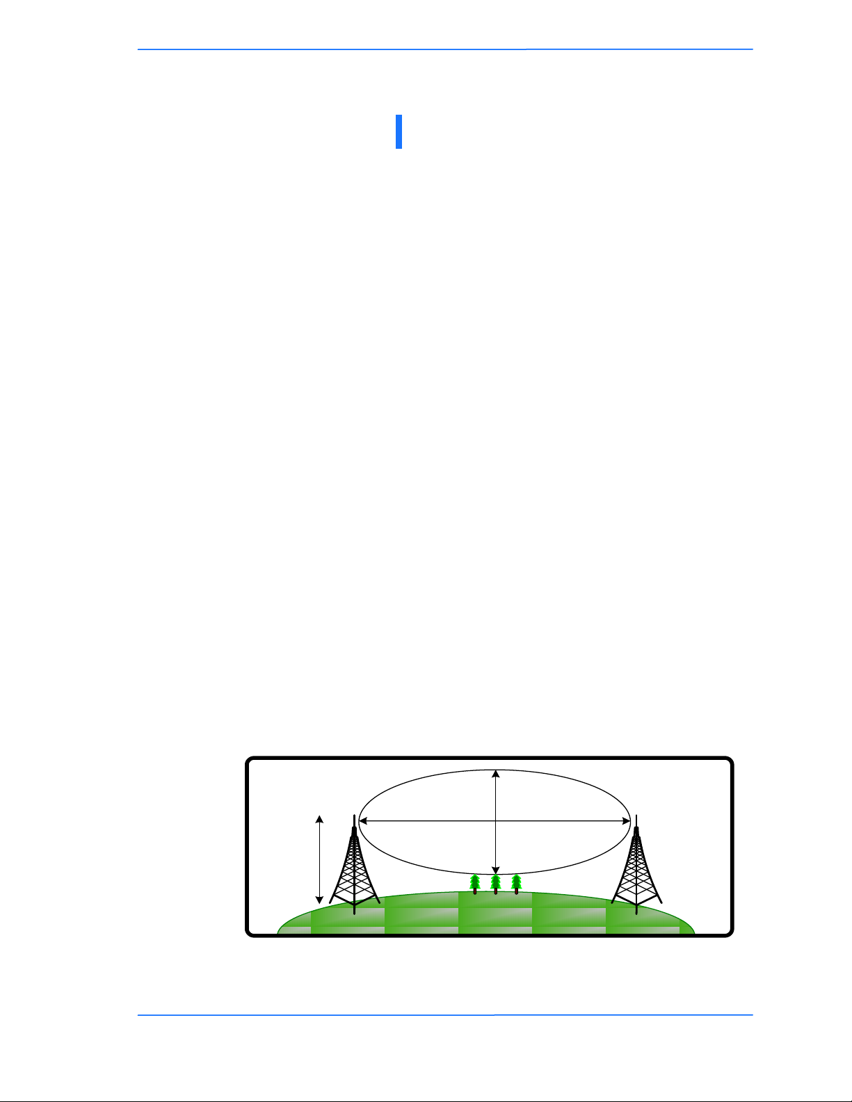
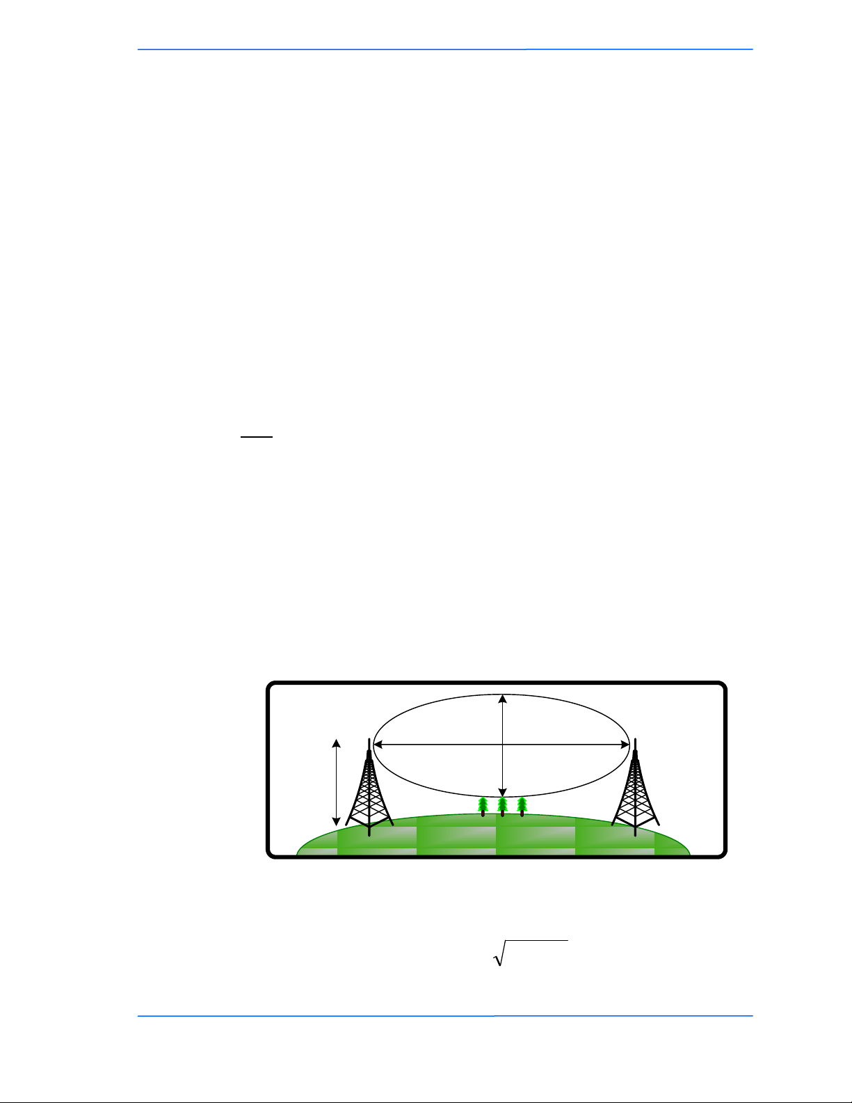
Ensure the CPE is within line-of-sight of the access point. The line-of-sight is an
ellipse, called Fresnel zone. This zone should be clear of obstacles since
obstructions will impede performance of the device.
Fresnel zone
TR-5A Series
Pitt Meadows, B.C. Canada V3Y 2V4
111
This document is intended for Public Distribution
19473 Fraser Way,
2-1
Page 11

Tranzeo Wireless Technologies
Polarity
Determine if the antenna‘s polarization will be horizontal or vertical before
installation. The TR-5A radios can be used in either polarity. The Ethernet boot
cover should always be placed so that the cable runs toward the ground for
maximum environmental protection.
Power Supply
Only use a power adapter approved for use with the TR-5A Series radio.
Otherwise, the product may be damaged and will not be covered by the Tranzeo
warranty.
Chapter 2: Hardware Installation
TR-5A Series
Pitt Meadows, B.C. Canada V3Y 2V4
222
This document is intended for Public Distribution
19473 Fraser Way,
2-2
Page 12
Tranzeo Wireless Technologies
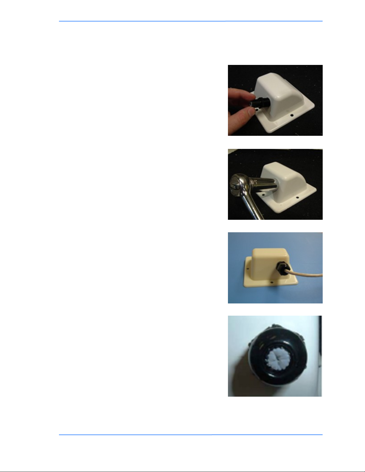
Installing the Ethernet Cable
Step 1:
Insert the strain relief, without the cap nut,
into the port opening of the boot cover.
Step 2:
Using a 3/4‖ wrench, tighten the strain
relief until it touches the boot cover.
IMPORTANT! Use hand tools only. Do
not over tighten.
Chapter 2: Hardware Installation
Step 3:
Put the cap nut back over the strain relief
and insert the Cat 5 cable through it. Wire
the cable following the EIA/TIA T568B
standard, and attach the RJ-45 connectors
to each end of the cable. (See Appendix F:
Wiring Standard).
Step 4:
If you purchased the device with a dual
port cover, repeat steps 1, 2, and 3 for the
second port.
IMPORTANT! If you are not going to use
the second port, insert the strain relief into
the boot cover and tighten the cap nut to
ensure a weather-tight seal, as shown in
the picture.
TR-5A Series
Pitt Meadows, B.C. Canada V3Y 2V4
333
This document is intended for Public Distribution
19473 Fraser Way,
2-3
Page 13
Tranzeo Wireless Technologies
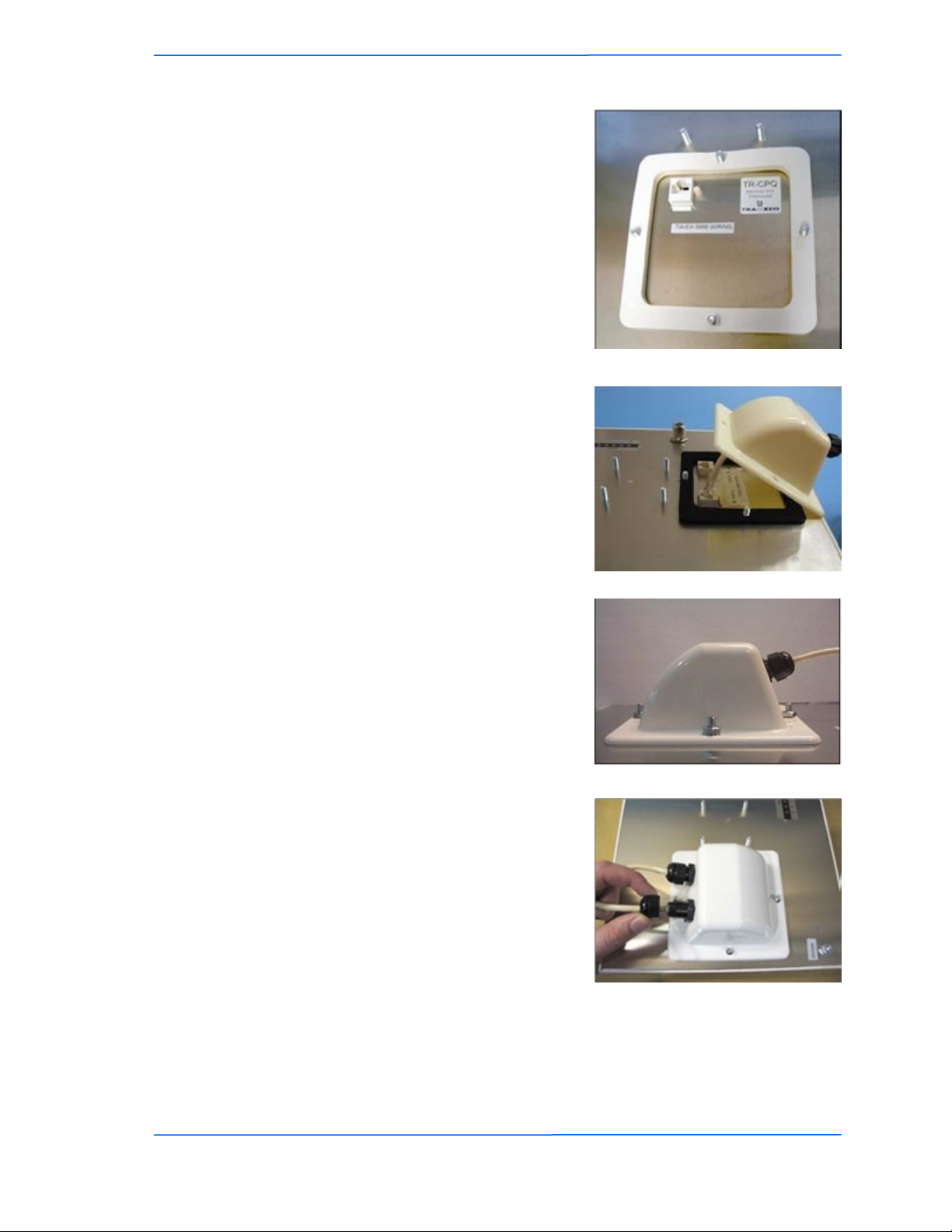
Step 5:
Place the gasket—with the adhesive side
facing up—over the 4 studs around the port
of the radio. Flatten the gasket ensuring
there are no gaps. Remove the backing.
Step 6:
Plug the Cat 5 cable inserted in the boot
cover into the port. Remember to place the
boot cover according to the desired
polarization, so that the strain relief faces
the ground.
Chapter 2: Hardware Installation
Step 7:
Fit the boot cover over the 4 studs and the
gasket. Secure with 4 keps nuts. Tighten
with a 3/8‖ wrench until the gasket is at
least 50% compressed.
Step 8:
Make sure the cap nut of the strain relief is
tightened properly to ensure a weatherproof seal.
IMPORTANT! Hand tighten only. Do not
over tighten as you may damage the
weather-tight seal of the strain relief.
TR-5A Series
Pitt Meadows, B.C. Canada V3Y 2V4
444
This document is intended for Public Distribution
19473 Fraser Way,
2-4
Page 14
Tranzeo Wireless Technologies
Mounting the Radio
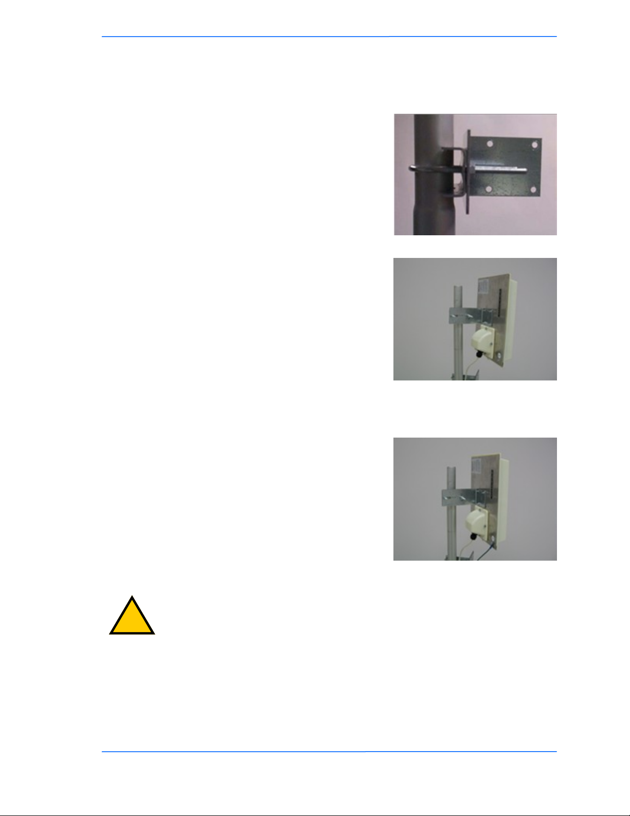
Step 9:
Attach the mounting bracket to the pole
using the U-bolt. Secure the U-bolt with
the lock washers and the nuts. Align if
necessary, and then tighten the nuts enough
to prevent any movement.
Step 10:
Fit the radio to the mounting bracket.
Secure the radio with keps nuts.
IMPORTANT! The strain relief must be
always facing the ground.
Chapter 2: Hardware Installation
Grounding the Antenna
Step 11:
Using a #6 green grounding wire, connect
the grounding lug on the radio to a proper
ground. See Appendix A: Grounding and
Lighting Protection Information.
IMPORTANT: This device must be grounded. Connect the green grounding wire
!
to a known good earth ground, as outlined in the National Electrical Code. See
Appendix A: Grounding and Lightning Protection Information for details.
TR-5A Series
Pitt Meadows, B.C. Canada V3Y 2V4
555
This document is intended for Public Distribution
19473 Fraser Way,
2-5
Page 15
Tranzeo Wireless Technologies
Connecting the Radio
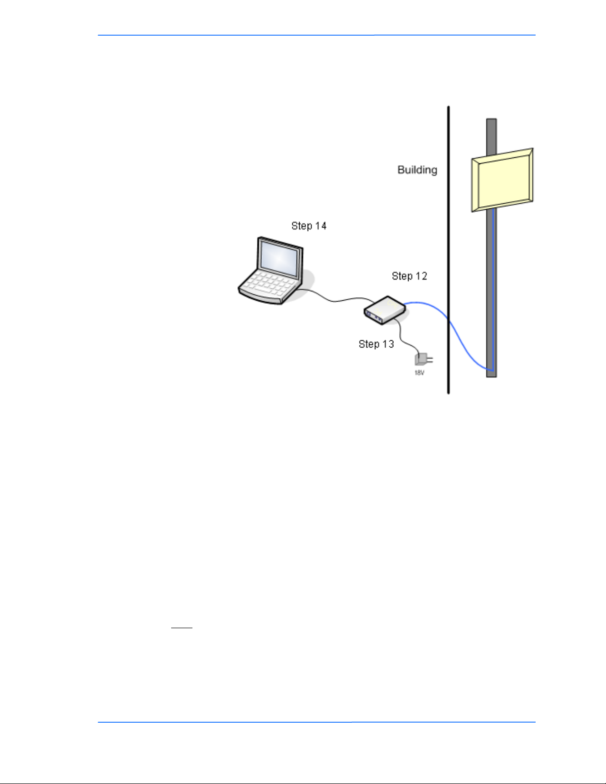
Step 12:
Connect the Cat 5 cable from the radio into
the RJ-45 jack marked ―CPE‖ on the POE
adapter. The POE adapter is not weatherproof and should be installed indoors.
Chapter 2: Hardware Installation
Step 13:
Connect the power adapter to the POE
adapter and plug the other end to an outlet.
The POE adapter will be powered on and
the power indicator on the top panel will
turn on. We recommend connecting the
power adapter to an outlet with surge
suppression capability with an uninterrupted
power supply (UPS) for reduced outages.
IMPORTANT! Use the power adapter
supplied with the radio. Otherwise, it may
be damaged.
Step 14:
To configure the TR-5A Series radio,
connect the Ethernet cable to the POE
adapter and to a computer. Ensure that the
distance between the computer and the
radio does not exceed 300 ft (90 m).
Note: If connecting to a hub or switch, a
crossover cable may be required.
TR-5A Series
Pitt Meadows, B.C. Canada V3Y 2V4
666
This document is intended for Public Distribution
19473 Fraser Way,
2-6
Page 16

Tranzeo Wireless Technologies
Best Practices
Follow these practices to ensure a correct installation and grounding.
Always try to run long Cat 5 and LMR cables inside of the mounting pole.
This helps to insulate the cable from any air surges.
Keep all runs as straight as possible. Never put a loop into the cables.
Test all grounds to ensure that you are using a proper ground. If using an
electrical socket for ground, use a socket tester, such as Radio Shack 22-141.
Keep a copy of the National Electrical Code Guide at hand and follow its
recommendations.
If you are in doubt about the grounding at the location, drive your own rod
and bond it to the house ground. At least you will know that one rod is
correct in the system.
Chapter 2: Hardware Installation
TR-5A Series
Pitt Meadows, B.C. Canada V3Y 2V4
777
This document is intended for Public Distribution
19473 Fraser Way,
2-7
Page 17
Tranzeo Wireless Technologies
The TR-5A Series radios can be configured through an HTML configuration
interface, accessible using any Internet browser. The configuration interface
allows you to define and change settings, and also shows information about the
performance of the device.
In this chapter we‘ll cover how to access the configuration interface, configure the
TR-5A Series radio, and interpret the information displayed in the interface.
Depending on whether the device is defined as an AP or CPE (infrastructure
station), some menu options, windows, and fields in the interface may vary or may
not appear at all. We‘ll indicate so when describing each window.
Connecting to the Radio
Before accessing the configuration interface, you have to change the network
connection settings in your computer to be on the same subnet as the radio.
Chapter 3: Configuration
Chapter 3: Configuration
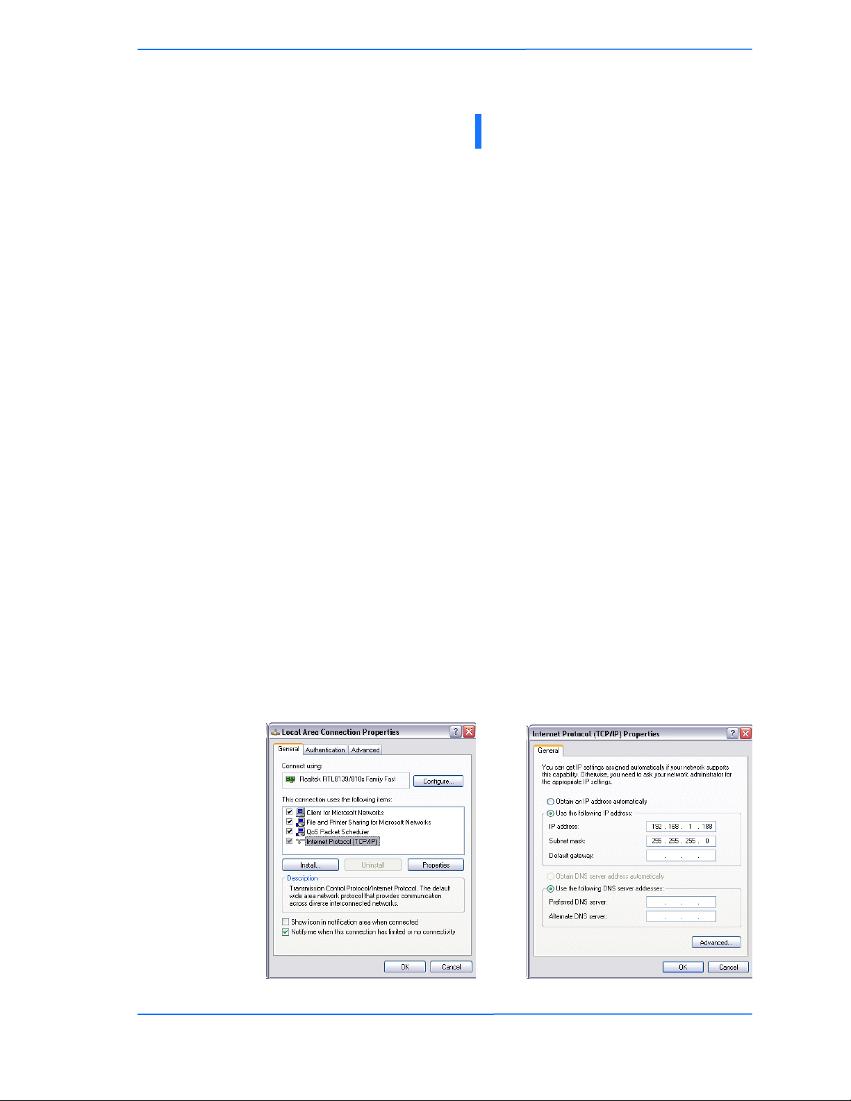
Changing the IP Address - Windows XP
1. In your computer, open Control Panel > Network Connections > Local Area
Connection.
2. In Local Area Connection Status > General, click Properties.
3. In Local Area Connection Properties > General, select Internet Protocol
(TCP/IP) and click Properties.
4. In Internet Protocol (TCP/IP) Properties > General, select Use the following
IP address.
5. Enter your IP address and Subnet Mask. The default IP address of the radio
is 192.168.1.100, which cannot be used here.
6. Click OK and Close.
TR-5A Series
Pitt Meadows, B.C. Canada V3Y 2V4
111
This document is intended for Public Distribution
19473 Fraser Way,
3-1
Page 18
Tranzeo Wireless Technologies
Changing the IP Address Using the Tranzeo Victor Program
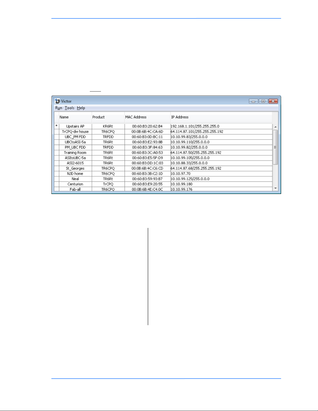
The Tranzeo Victor Program is a utility that allows users to quickly change the IP
address of the Tranzeo radios. It sends out a broadcast on the network and displays
a list of other Tranzeo radios connected, from which you can configure the IP
address for your device.
Note: The Tranzeo Victor Program cannot locate radios through routers.
Chapter 3: Configuration
Columns
Name:
Displays the Device Name as set in the Administrative
Options Page of the HTTP Interface
Product:
Mac Address:
IP Address:
Display the Tranzeo Product Name. This is a read
only Value.
Displays the MAC address the device is current using.
If the MAC Cloning option has been turned on, the
MAC Address that appears is as set in the Network
Interface. If the MAC Cloning feature has not been
used, then the Factory set MAC Address appears.
Displays the Ip Address and Netmask as set in the
Network Page of the HTTP Interface
.
The Tranzeo Victor Program has a number of menu options.
TR-5A Series
Pitt Meadows, B.C. Canada V3Y 2V4
222
This document is intended for Public Distribution
19473 Fraser Way,
3-2
Page 19

Tranzeo Wireless Technologies
Run Menu
Chapter 3: Configuration
Scan:
Locates Tranzeo radios connected to the network. A *
appears before the name when the radio is in the same
Detail:
subnet as your PC.
Displays more info for a selected radio, such as IP
Mode, Gateway, etc .This option is only available
when a device is selected.
Set IP:
Using this option you set the device to have a DCHP
address, or set the Static Details.
Disabling Locator Write Access under the
Administrative Settings page of the HTTP interface
will cause the device to not accept these changes.
This option is only available when a device is selected.
Reset:
Reboots the radio. This option is only available when
a device is selected.
Quit:
Exits the program.
Tools Menu
Open Browser:
Options:
Scan Timeout:
Request Timeout:
Web Browser:
Protocol:
Scan when Start:
Opens the HTTP page of the selected device in the
Web Brower.
Allows you to adjust some the Program‘s settings
Sets the amount of time the program will wait for
Scan results. Increase this value if you find that not
every radio is being found.
Sets the amount of time the program will wait for
Detail results. Increase this value if you find that
Detail requests are timing out.
Victor uses the system browser by default. IF you
wish to use an alternative browser to access your
Tranzeo Radios, enter the full path to the alternative
browser here.
The TR-5a Series use the Legacy protocol.
Tranzeo‘s WiMAX, EL, EN and many other series of
Radios use the newer TDP (Tranzeo Discovery
Protocol).
Enables the automatic Scan when the program is
started.
Help Menu
The About option displays the Version Number of the Program.
TR-5A Series
Pitt Meadows, B.C. Canada V3Y 2V4
333
This document is intended for Public Distribution
19473 Fraser Way,
3-3
Page 20
Tranzeo Wireless Technologies
Login into the Configuration Interface
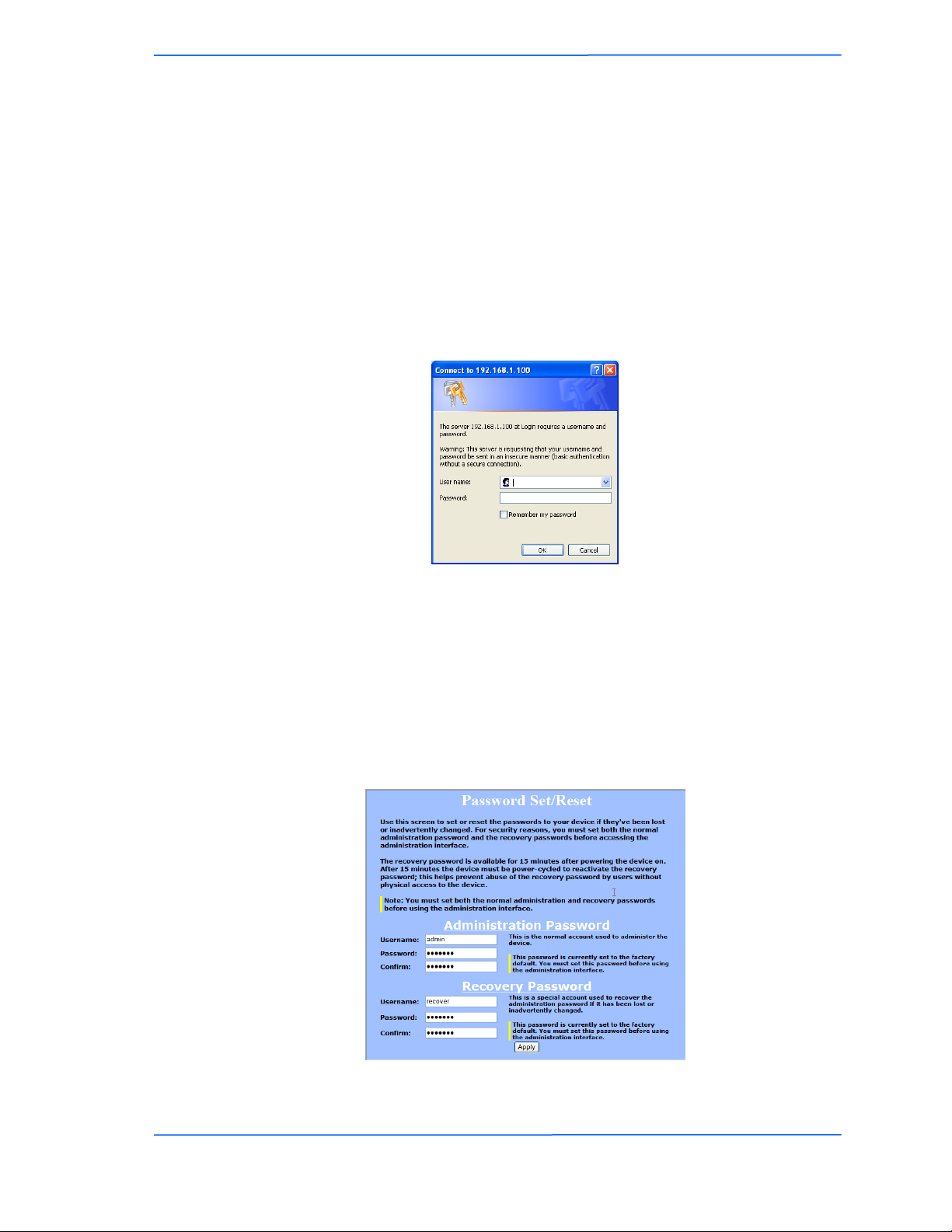
After defining the network settings, follow these steps to login into the Tranzeo
Configuration Interface.
1. Open your Internet browser (Internet Explorer, Netscape, or Firefox).
2. In the address bar, type your IP address (default IP: http://192.168.1.100).
3. In the login dialog, enter your Username and Password (if you‘re a first-
time user, follow the instructions below).
4. Click OK. You will then access the configuration interface.
If you‘re a first-time user:
1. Enter the default username admin and the default password default.
Chapter 3: Configuration
2. In the Password Set/Reset window, change the Administration and
Recovery* passwords. They cannot be left as default and must be different
from each other. You can change the usernames too.
3. Click Apply to save the changes.
4. You will be prompted to enter your new username and password in the login
dialog. You will then access the configuration interface.
* The recovery username and password are used to access the Password Set/Reset
window if the administration password is lost.
TR-5A Series
Pitt Meadows, B.C. Canada V3Y 2V4
444
This document is intended for Public Distribution
19473 Fraser Way,
3-4
Page 21
Tranzeo Wireless Technologies
Information Page
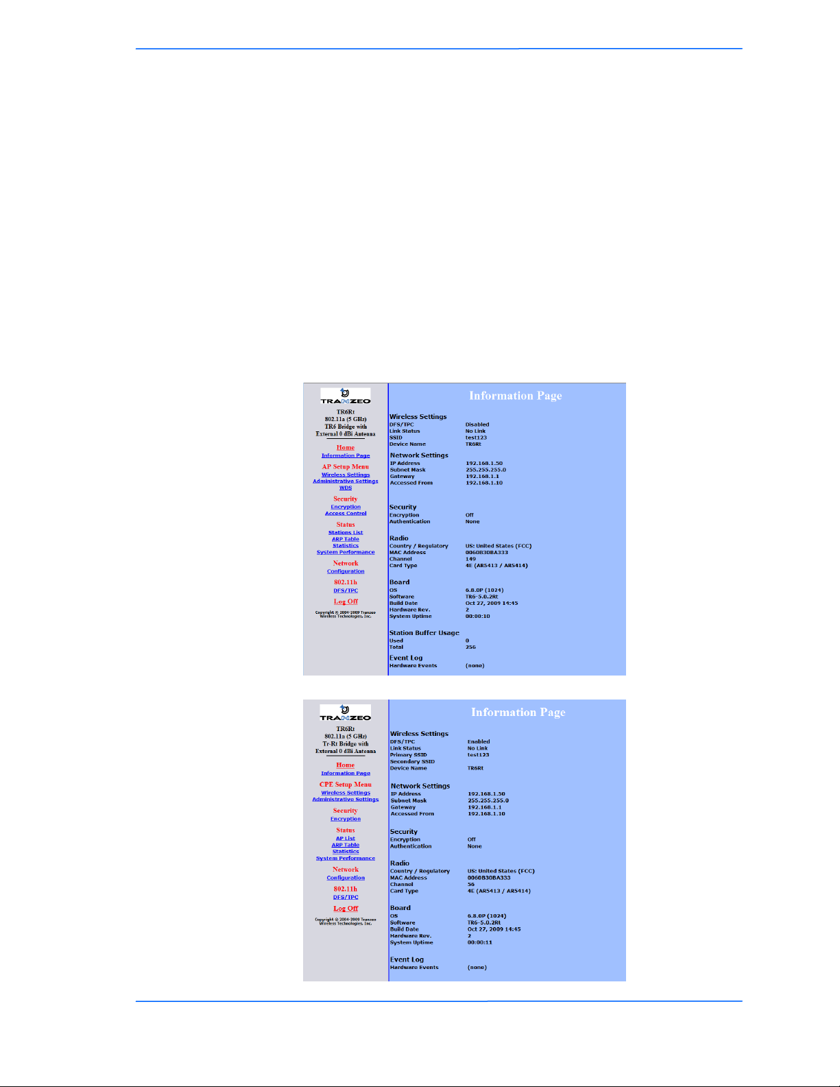
This is the first window of the configuration interface. It shows the main menu and
information about the device settings, like wireless, network, and security settings.
The menu is divided in four sections:
Setup Menu
Security
Status
Network
Each section contains navigation links to the configuration windows, some of
which may be different for access points and CPEs.
Information Page - AP
Chapter 3: Configuration
TR-5A Series
Pitt Meadows, B.C. Canada V3Y 2V4
Information Page - CPE
555
This document is intended for Public Distribution
19473 Fraser Way,
3-5
Page 22
Tranzeo Wireless Technologies
Setup Menu
In this section you would be able to configure wireless and administrative settings
for the TR-5A Series radio.
Wireless Settings - Basic Tab, Access Point
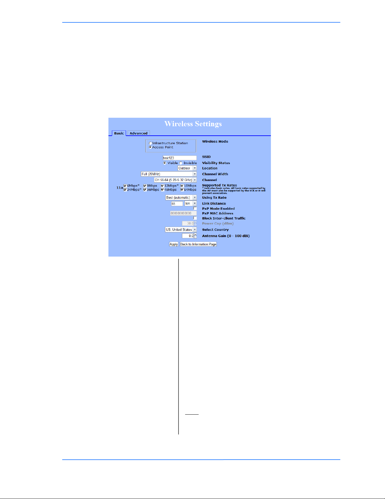
This window displays the wireless configuration of the device. The contents are
slightly different for access point and CPE.
Wireless Mode:
Chapter 3: Configuration
Define if your device will operate as Infrastructure
Station (CPE) or Access Point.
Visibility Status*:
Channel Width:
Using TX Rate:
* Feature available only in access point wireless mode.
(1)
In the FCC Domain this setting has no effect.
TR-5A Series
Pitt Meadows, B.C. Canada V3Y 2V4
SSID:
The Service Set Identifier (SSID) is the name that
identifies a specific wireless LAN. Devices must have
the same SSID to communicate with each other.
You can set your access point to be Visible or
Invisible to clients.
Location:
Channel*:
You can set the location of the radio to be Outdoor or
Indoor.
(1)
Select the channel that the access point and clients use.
Select the channel width to use. This value must
match on both the AP and CPE.
The transmission speed at which the radio and access
point communicate with each other.
Note: Setting this rate below the maximum possible
does not limit bandwidth and often has a negative
impact on the operation of your network.
666
This document is intended for Public Distribution
19473 Fraser Way,
3-6
Page 23

Tranzeo Wireless Technologies
Supported Tx Rates:
Link Distance:
PxP Mac Address:
Block Inter-Client
Antenna Gain:
* Feature available only in access point wireless mode.
(1)
In the FCC Domain this setting has no effect.
PxP Mode:
Traffic*:
Power Cap:
Country:
Chapter 3: Configuration
Select the rates at which you the radio will transmit.
*indicates basic rates. All Basic rates supported by the
AP must also be supported by the CPE or it will
prevent association.
This is the distance between the CPE and access point.
This setting is necessary to define the correct ACK
timing. Setting this value too low or too high will
result in low throughput and high retries.
Follow the instructions in next page.
Follow the instructions in next page.
Check to block wireless communications between
clients on the access point.
It is the maximum output power of the radio.
Select the country where the device is located. Setting
an incorrect country may be considered a violation of
the applicable law, as rules differ in each country.
Select the gain of the antenna. This information must
be set by the installer at the time of installation.
(1)
TR-5A Series
Pitt Meadows, B.C. Canada V3Y 2V4
777
This document is intended for Public Distribution
19473 Fraser Way,
3-7
Page 24
Tranzeo Wireless Technologies
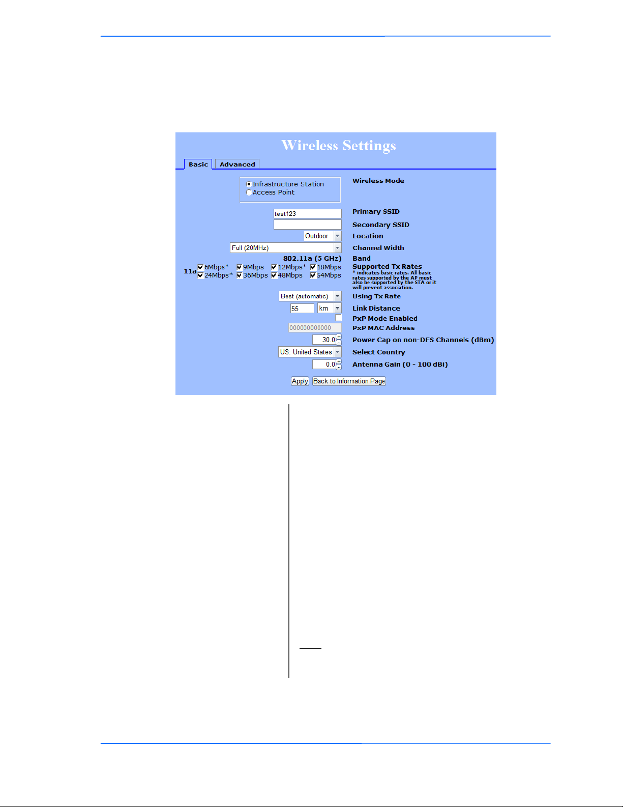
Wireless Settings - Basic Tab, Infrastructure Station
This window displays the wireless configuration of the device. The contents are
slightly different for access point and CPE.
Wireless Mode:
SSID:
Chapter 3: Configuration
Define if your device will operate as Infrastructure
Station (CPE) or Access Point.
The Service Set Identifier (SSID) is the name that
identifies a specific wireless LAN. Devices must have
the same SSID to communicate with each other. In
Infrastructure Station mode (CPE), you can enter
primary and secondary SSIDs when using two access
points in the network. Clients will connect to the
secondary access point when the primary is
unavailable or goes down.
Channel Width:
Using TX Rate:
* Feature available only in access point wireless mode.
(1)
In the FCC Domain this setting has no effect.
TR-5A Series
Pitt Meadows, B.C. Canada V3Y 2V4
Location:
You can set the location of the radio to be Outdoor or
Indoor.
(1)
Select the channel width to use. Must match on both
the AP and CPE.
The transmission speed at which the radio and access
point communicate with each other.
Note: Setting this rate below the maximum possible
does not limit bandwidth and often has a negative
impact on the operation of your network.
888
This document is intended for Public Distribution
19473 Fraser Way,
3-8
Page 25

Tranzeo Wireless Technologies
Supported Tx Rates:
Link Distance:
PxP Mac Address:
Antenna Gain:
PxP Mode:
Power Cap:
Country:
Chapter 3: Configuration
Select the rates at which you the radio will transmit.
*indicates basic rates. All Basic rates supported by the
AP must also be supported by the CPE or it will
prevent association.
This is the distance between the CPE and access point.
This setting is necessary to define the correct ACK
timing. Setting this value too low or too high will
result in low throughput and high retries.
Follow the instructions in next page.
Follow the instructions in next page.
It is the maximum output power of the radio.
Select the country where the device is located. Setting
an incorrect country may be considered a violation of
the applicable law, as rules differ in each country.
Select the gain of the antenna. This information must
be set by the installer at the time of installation.
TR-5A Series
Pitt Meadows, B.C. Canada V3Y 2V4
999
This document is intended for Public Distribution
19473 Fraser Way,
3-9
Page 26
Tranzeo Wireless Technologies
Antenna
Height
r = radius
d = distance
)4/(3.43 fdr
PxP Setup
Point to Point (PxP) mode is a Layer 2 transparent protocol optimized for
backhaul use. PxP mode is recommended whenever two network segments are to be bridged.
To operate the radio in PxP mode:
1. Set one radio to Access Point and the other to Infrastructure Station.
2. Enter the same SSID on both radios.
3. Set the Channel on the access point.
4. On both radios, enter the Mac address of the opposite radio in the PxP Mac
Address field (no colons).
5. Check off PxP Mode Enabled.
Note:
Chapter 3: Configuration
In PxP mode, the LEDs on the radios will operate the same as in Infrastructure
Station mode on both AP and CPE unit, with LEDs proportional to signal strength.
PxP Guidelines
There are a few guidelines you should follow when putting in a PxP link.
1. Determine the locations for each side of the link.
2. Determine the distance of the link and the heights of the installed equipment.
3. Using the details from step 2 check the Fresnel Zone and line of site.
4. Verify that the line of site is free of obstruction.
The cross section radius of the Fresnel zone is the highest in the center of the RF LoS
which can be calculated as:
TR-5A Series
Pitt Meadows, B.C. Canada V3Y 2V4
where r = radius in feet, d = distance in miles, and f = frequency in GHz.
Fresnel zone
101010
This document is intended for Public Distribution
19473 Fraser Way,
3-10
Page 27
Tranzeo Wireless Technologies
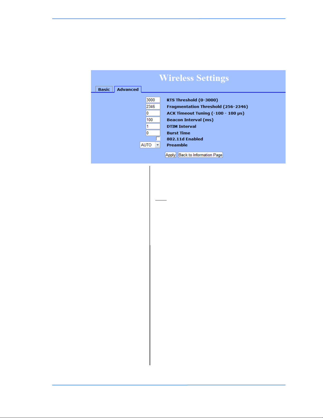
Wireless Settings - Advanced Tab, Access Point
This window displays the advanced wireless configuration of the device. The
contents are slightly different for access point and CPE.
RTS Threshold:
Chapter 3: Configuration
This is the maximum size for a packet to be sent
automatically. When it exceeds the RTS threshold, the
CPE sends first a ‗request to send‘ (RTS) to the access
point before sending the packet.
Note: The more clients you have, the lower the value
should be set.
Fragmentation
Threshold:
This is the size at which packets are fragmented in
order to be transmitted. Setting this value too low
decreases the amount sent on each transmission. In
noisy areas, this can improve performance. However,
in quiet areas, this will decrease throughput.
ACK Timeout Tuning:
The time that the radio waits for an acknowledgment
(ACK) from the access point accepting transmission
before re-attempting to send the data. This is an offset
from the ACK timing set by the link distance.
Beacon Interval:
This is the rate at which the access point broadcasts its
beacons.
DTIM Interval:
The DTIM interval (Delivery Traffic Indication
Message) helps to keep marginal clients connected by
sending wake up frames.
Burst Time:
This allows to send data without stopping. Note that
other wireless devices in the network will not be able
to transmit data for this number of microseconds.
802.11d Enabled:
Preamble:
Check to operate in 802.11d mode.
Select type: Long uses long preamble only, Auto
(recommended) tries short preamble first, then long.
(1)
In the FCC Domain this setting has no effect.
(1)
TR-5A Series
Pitt Meadows, B.C. Canada V3Y 2V4
111111
This document is intended for Public Distribution
19473 Fraser Way,
3-11
Page 28
Tranzeo Wireless Technologies
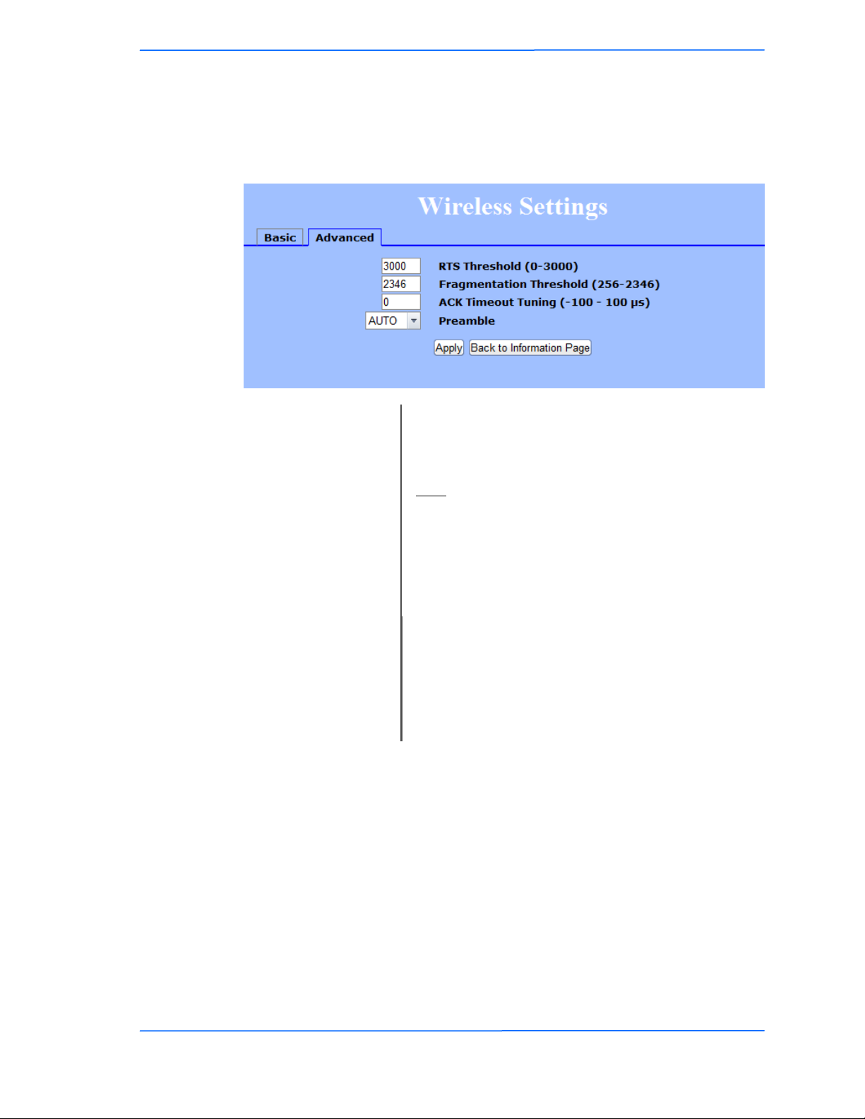
Wireless Settings - Advanced Tab, Infrastructure (CPE)
This window displays the advanced wireless configuration of the device. The
contents are slightly different for access point and CPE.
RTS Threshold:
Fragmentation
Threshold:
Chapter 3: Configuration
This is the maximum size for a packet to be sent
automatically. When it exceeds the RTS threshold, the
CPE sends first a ‗request to send‘ (RTS) to the access
point before sending the packet.
Note: The more clients you have, the lower the value
should be set.
This is the size at which packets are fragmented in
order to be transmitted. Setting this value too low
decreases the amount sent on each transmission. In
noisy areas, this can improve performance. However,
in quiet areas, this will decrease throughput.
ACK Timeout Tuning:
TR-5A Series
Pitt Meadows, B.C. Canada V3Y 2V4
The time that the radio waits for an acknowledgment
(ACK) from the access point accepting transmission
before re-attempting to send the data. This is an offset
from the ACK timing set by the link distance.
Preamble:
Select type: Long uses long preamble only, Auto
(recommended) tries short preamble first, then long.
121212
This document is intended for Public Distribution
19473 Fraser Way,
3-12
Page 29
Tranzeo Wireless Technologies
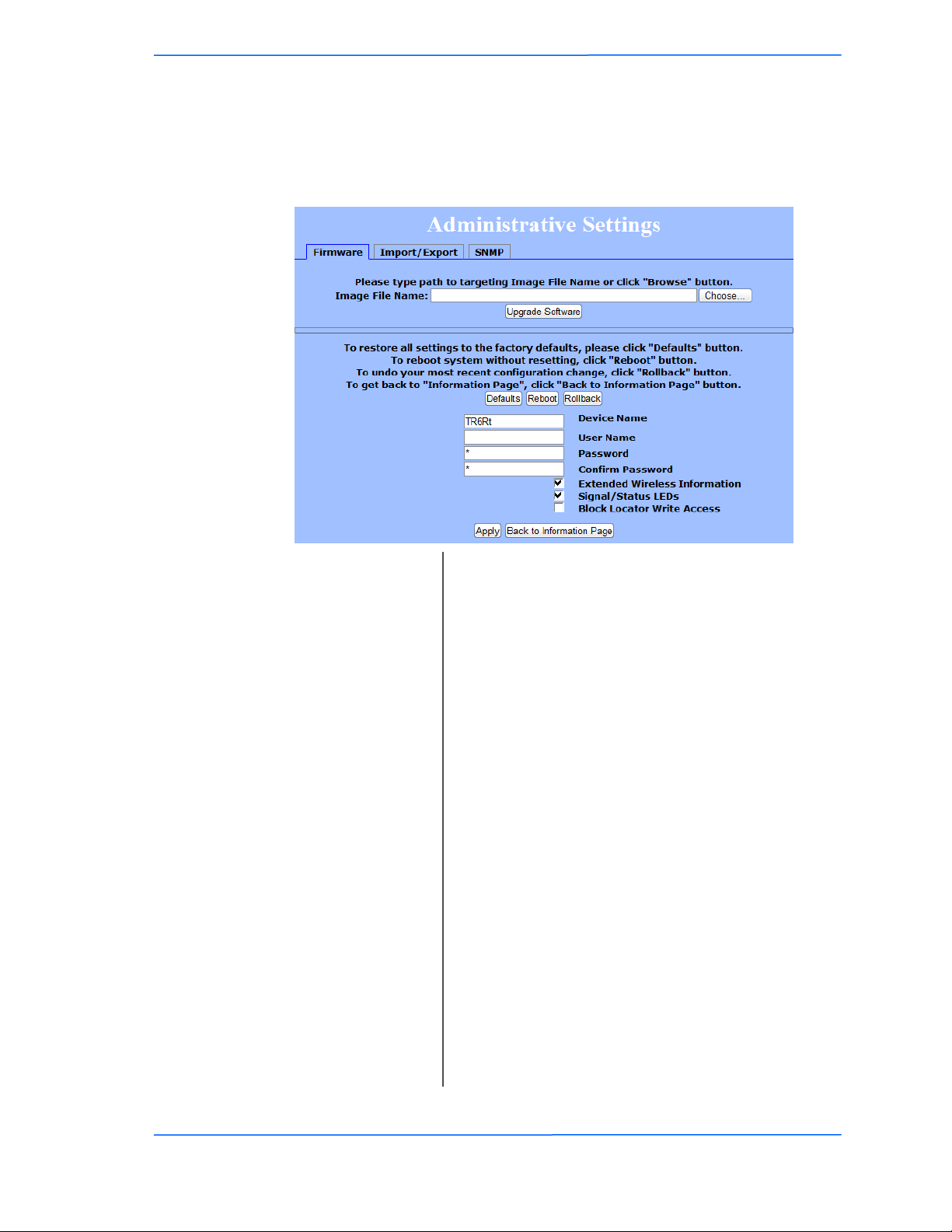
Administrative Settings - Firmware Tab
Use this window to upgrade the software, change your password, and define
SNMP parameters.
Chapter 3: Configuration
Upgrade Software:
Defaults:
Reboot:
Rollback:
Device Name:
User Name:
Password:
Confirm Password:
Extended Wireless
Information:
Signal/Status LEDs:
Block Locator Write
Access:
Enter the location of the software update file or
Browse to locate it in your computer. Click Upgrade
Software. If the radio does not refresh the Information
Page after 1 minute, press Refresh, Reload or F5.
Verify the new firmware is installed correctly.
Returns all settings to factory defaults, including
passwords.
Restarts the system without changing settings.
To undo the most recent change.
It is the network name of the device. This name
appears in the Locator and on the Tranzeo stations list.
This is the login username.
Enter a new password if you want to change it.
Re-type the new password.
Enables extended information (name and IP address),
which is only displayed with Tranzeo access points.
Un-check to turn off the LED panel indicators.
Blocks locator write access to the device.
TR-5A Series
Pitt Meadows, B.C. Canada V3Y 2V4
131313
This document is intended for Public Distribution
19473 Fraser Way,
3-13
Page 30
Tranzeo Wireless Technologies
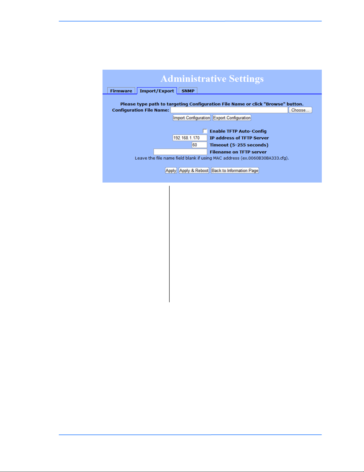
Administrative Settings - Import / Export
Use this window to import and export settings.
Chapter 3: Configuration
Configuration File
Name:
Enable TFTP
Auto-Config:
IP Address:
Timeout:
Filename:
Enter the location of the configuration file or Browse
to locate it in your computer. Click Import
Configuration to import setting or Click Export
Configuration to export the settings. See Appendix J
for more information on this feature,
Enables the radio to pull its configuration directly
from a TFPT server at Boot up. See Appendix J for
more information on this feature,
Address of the TFTP server.
Timeout if file not available. (5-255 Seconds)
Filename of the configuration file on the TFTP Server
for auto-config. Leave the file name blank if using
MAC address (eg. 0060B30BA333.cfg).
TR-5A Series
Pitt Meadows, B.C. Canada V3Y 2V4
141414
This document is intended for Public Distribution
19473 Fraser Way,
3-14
Page 31
Tranzeo Wireless Technologies
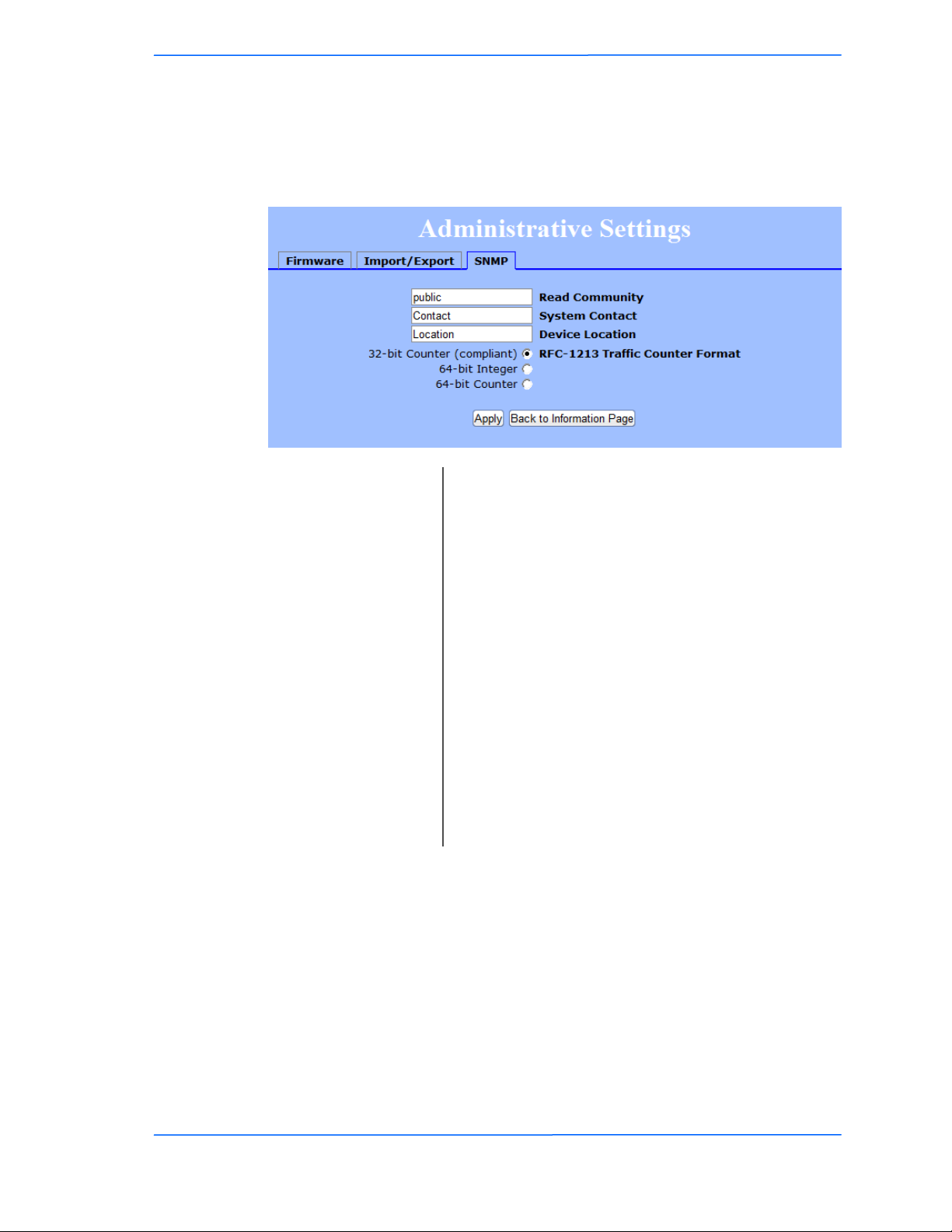
Administrative Settings - SNMP Tab
Use this window to define SNMP parameters.
Chapter 3: Configuration
Read Community:
System Contact:
Device Location:
Counter Format:
Device Name:
This is the read community string.
IT IS HIGHLY RECOMMENDED THAT YOU
CHANGE THIS VALUE FROM THE
DEFAULTS.
Enter the name of the system contact to be reported by
SNMP.
Enter the location of the device to be reported by
SNMP.
Select the counter format that you that would like to
use. Some SNMP programs can not address a 64 bit
number in the Traffic counter. If your SNMP can
address a 64 bit number, we highly suggest using a 64
bit number due to the high number of bits a radio can
transfer.
It is the network name of the device. This name
appears in the Victor Program and on the Tranzeo
stations list.
TR-5A Series
Pitt Meadows, B.C. Canada V3Y 2V4
151515
This document is intended for Public Distribution
19473 Fraser Way,
3-15
Page 32
Tranzeo Wireless Technologies
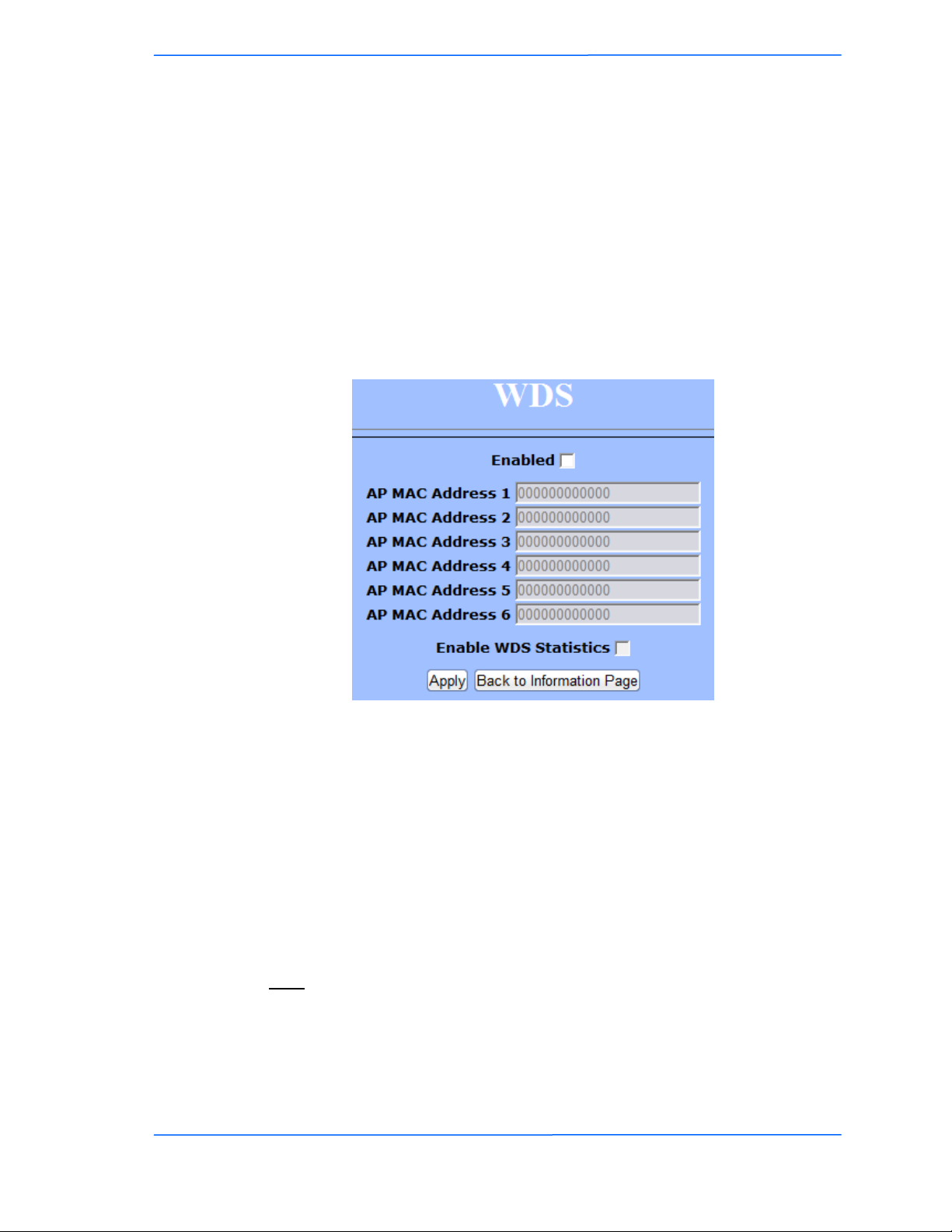
WDS (AP only)
The Wireless Distribution System (WDS) is a modification to the 802.11 standards that allows access points to communicate directly with each other. WDS
allows users to spread out coverage to a larger area without the need for a
backhaul link. The tradeoff is that overall throughput is greatly affected for all
users of the access points linked.
NOTE: WDS is not recommended for use with large numbers of clients or when
throughput needs to be maximized. In both cases, a dedicated PxP link should be
used. However, in areas of low density, WDS can allow an ISP to extend coverage
into an area at very low cost.
To set up WDS:
1. Select Enabled to activate WDS and click Apply.
Chapter 3: Configuration
2. Go to the Administrative Settings window and change the settings to
Defaults.
3. Go to the Wireless Settings window and set the same Channels for both
access points.
4. In the WDS settings window, enter the Mac address of the peer. Do not
insert colons or commas.
5. Click Apply.
Note:
WDS links don‘t appear in the Station List or Performance windows. To
monitor the link‘s strength and performance, use PxP mode.
Throughput is cut by 50% per link. 2 Radio in WDS mode will have 50% of
the normal bandwidth, 3 will have 25%, and so on.
WDS does not support WPA encryption.
TR-5A Series
Pitt Meadows, B.C. Canada V3Y 2V4
161616
This document is intended for Public Distribution
19473 Fraser Way,
3-16
Page 33
Tranzeo Wireless Technologies
Encryption
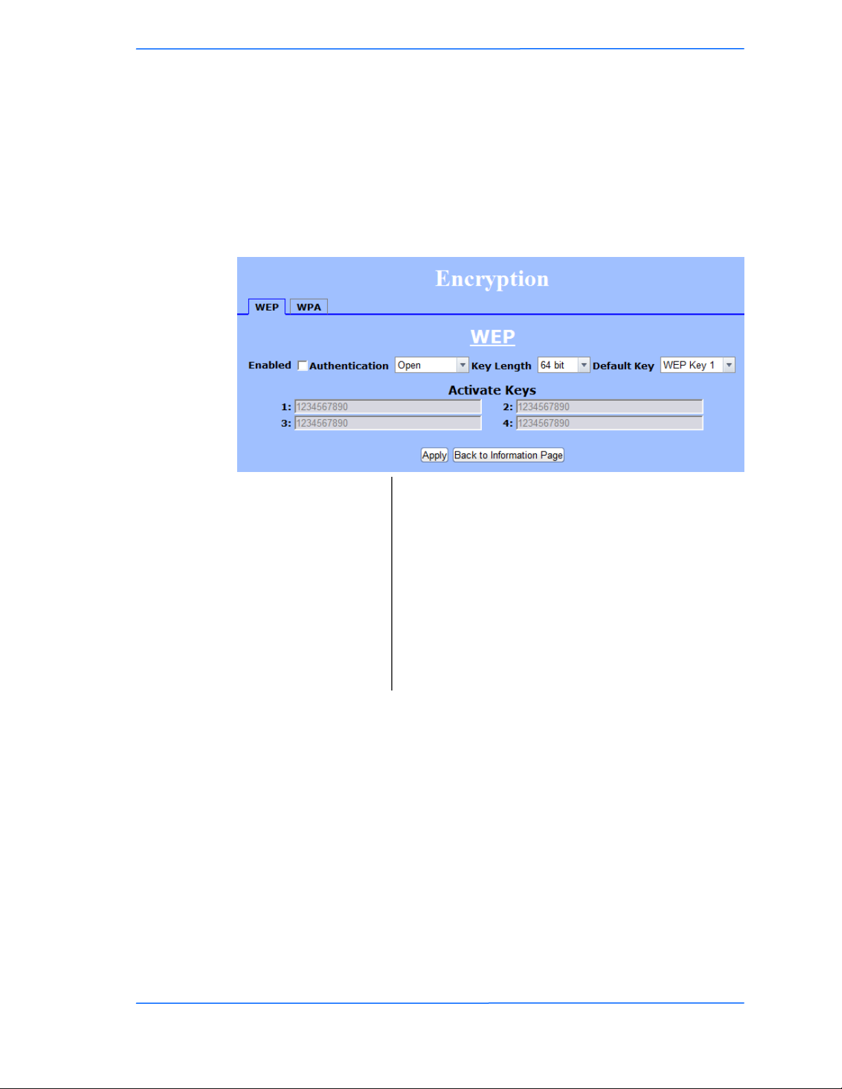
In this section you can configure both basic and advanced security settings for
your device.
WEP Settings
In this window you can define WEP parameters. WEP provides security by
encrypting data so that it‘s protected when transmitted from one point to another.
Chapter 3: Configuration
Enabled:
Authentication:
Key Length:
Default Key:
Activate Keys:
Check to turn on WEP security protocol.
Select your system to be open or shared. Open is
always recommended.
This is the level of encryption. Note that 64 bit is
referred to as 40 bit on some systems.
WEP 64 requires 10 Hex characters.
WEP 128 requires 26 Hex characters.
Select the default WEP key from the list.
Enter the four WEP keys you want to activate. Keys
must be entered in HEX only.
TR-5A Series
Pitt Meadows, B.C. Canada V3Y 2V4
171717
This document is intended for Public Distribution
19473 Fraser Way,
3-17
Page 34
Tranzeo Wireless Technologies
WPA Settings
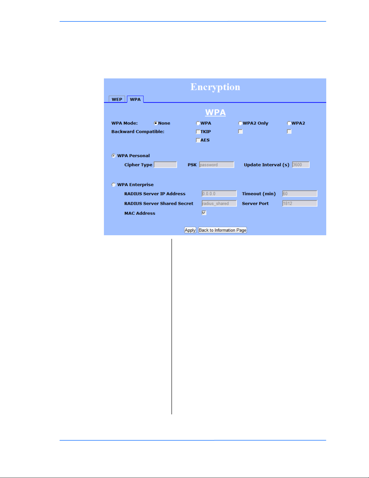
In this window you can enter WPA parameters. WPA provides a higher level of
security, enhancing the security features of WEP.
Backward Compatible:
Update Interval:
WPA Enterprise*:
* Feature available only in access point wireless mode.
WPA Mode:
Cipher Type:
PSK:
Chapter 3: Configuration
Select the WPA mode.
NOTE: Due to the way TKIP stores information, it
greatly reduces the number of client an AP can
address. With TKIP turned, an AP can only address
31 clients. AES is highly recommended as it does not
affect the number of clients, and is much more secure
than TKIP.
Select TKIP or AES backwards compatibility if
required. These options should only be selected if you
have Tranzeo units in your network that are not
running 3.x or higher firmware.
Select the level of encryption.
Enter your PSK password. Minimum 8 characters
This is the interval at which the PSK password will be
updated. The higher the number, the more often the
key will be updated, which increases security but can
reduce throughput.
Ensures that only authorized network users can access
the network. Enter the information about the RADIUS
server from your Internet Service Provider.
TR-5A Series
Pitt Meadows, B.C. Canada V3Y 2V4
181818
This document is intended for Public Distribution
19473 Fraser Way,
3-18
Page 35
Tranzeo Wireless Technologies
Access Control (AP only)
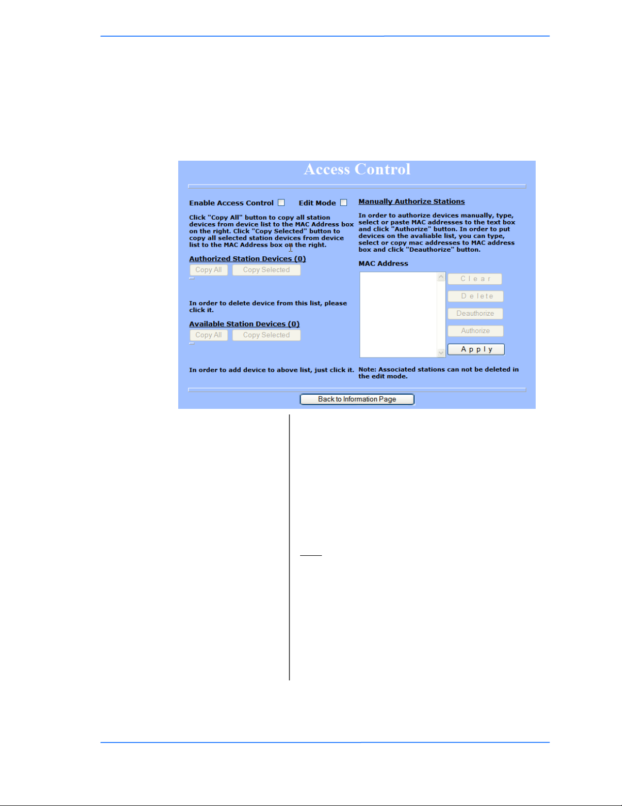
This feature allows you to control the what devices are allowed to associate to
your access point, in other words, to allow or deny access from other radios.
MAC access control offers a light weight method of controlling access to your
network.
Chapter 3: Configuration
Enable Access
Control:
Edit Mode:
Authorized Station
Devices:
Available Station
Devices:
Manually Authorize
Stations:
Select to enable MAC Access Control.
Check to make changes to access control settings such
adding or removing a MAC Address.
This is the list of the authorized devices. To change
current settings, check the devices and click Copy All
or Copy Selected. The devices will appear in the Mac
Address box on the right.
Note: If you are working via a radio link, add first the
MAC address of the station you are connecting from.
Otherwise, you will be locked out of the radio.
This list contains the devices available but not
authorized. To authorize them, check the devices and
click Copy All or Copy Selected. The devices will
appear in the Mac Address box on the right.
In this box you can perform different actions like
authorize, deauthorize and delete devices listed here.
TR-5A Series
Pitt Meadows, B.C. Canada V3Y 2V4
191919
This document is intended for Public Distribution
19473 Fraser Way,
3-19
Page 36
Tranzeo Wireless Technologies
DFS / TPC
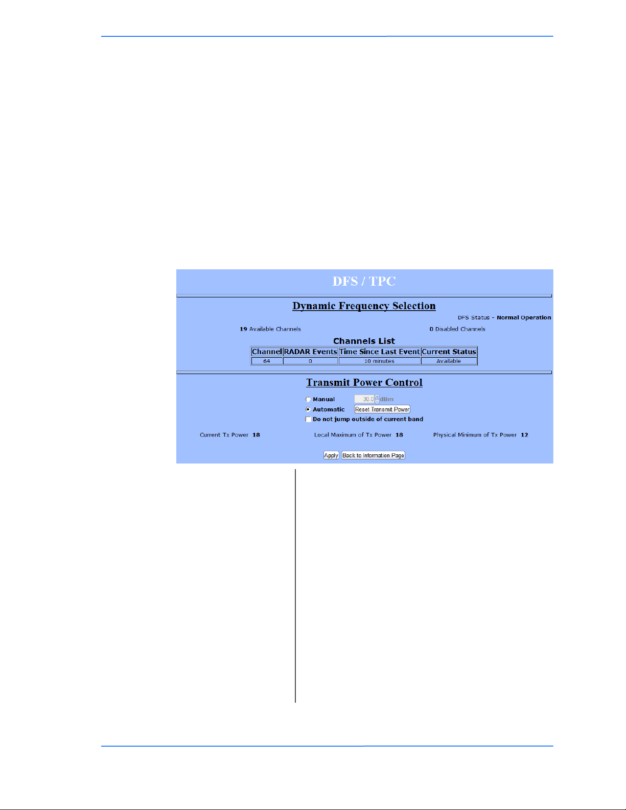
This section displays information about the Dynamic Frequency Selection (DFS)
and Transmit Power Control (TPC) Status information and configuration.
DFS/TPC is required for operation in certain frequency ranges as mandated by
local regulation. If the device detects radar on a give channel it must stop
transmitting and flag the channel as unusable for 30 minutes. The radio then
selects a new channel from the available channel list. The radio must scan this
channel for 60 seconds before starting to transmit. If radar is detected on the new
channel it must repeat the previous steps until it finds a free channel. If all the
channels show radar events the radio will have to wait for the 30 minute timeout to
try the channels again. As such, if you are in an area with radar events channels
requiring DFS/TPC are not recommended for backhaul use.
Chapter 3: Configuration
Available Channels:
Disabled Channels:
DFS Status:
Channel List:
Automatic:
Manual:
Displays operational status.
Displays the number of channels available for the
radio to select from.
Displays the number of channels disabled by radar
events.
Shows the channels that have seen radar events, the
number of radar events, the time since the last event,
and the current status of the channel.
Enables manual power control if allowed by local
regulations.
Allows the radio to automatically select the best
transmit power.
Do not jump outside of
TR-5A Series
Pitt Meadows, B.C. Canada V3Y 2V4
current band:
202020
This document is intended for Public Distribution
19473 Fraser Way,
Restricts the radio to stay within channels in the
current band when scanning for available channels.
3-20
Page 37
Tranzeo Wireless Technologies
Status
This section displays information about the status and performance of your radio.
Most options and information cannot be modified in this section.
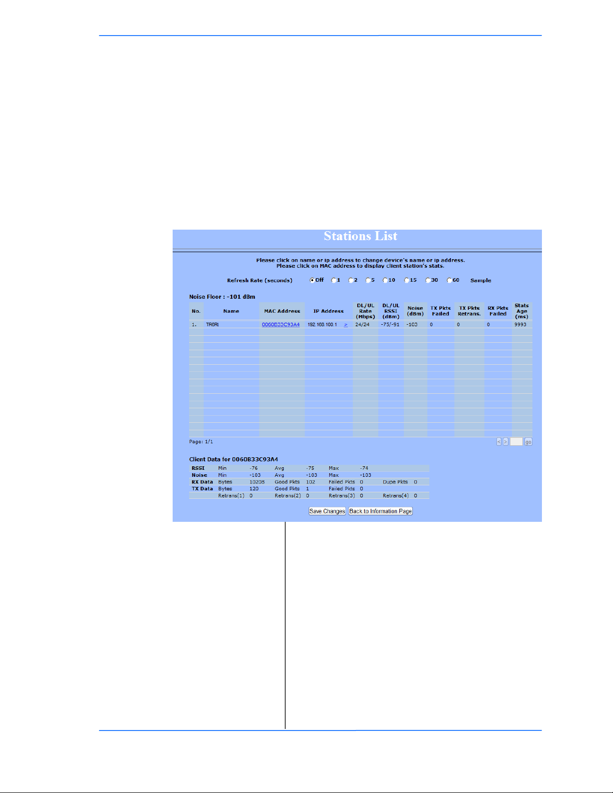
Stations List (AP only)
This window displays a list of the stations associated with the access point and
their connection statistics. The refresh rate option will reload the page after that
many seconds. When the page is collecting data, a Green bar will appear behind
the word Status. Clicking onto a client will display additional info at the bottom
of the page.
Chapter 3: Configuration
Name:
This information appears here when the device is a
Tranzeo CPE with the Extended Wireless
Information option turned on. Otherwise, the field
will be blank. You can manually enter a name by left
clicking on the field and typing in. However, if the
Mac Address:
Extended Wireless Information option is turned on
at the client, the name you entered will be overwritten
with the name on the client.
The Mac addresses of the associated stations.
TR-5A Series
Pitt Meadows, B.C. Canada V3Y 2V4
IP Address:
This data also appears when the Extended Wireless
Information checked. Click > to open a new browser
window to that client.
DL/UL Rate:
DL/UL RSSI:
212121
This document is intended for Public Distribution
19473 Fraser Way,
Indicates the Downlink and Uplink rates in Mbps.
Indicates the Downlink and Uplink RSSI in dBm.
3-21
Page 38
Tranzeo Wireless Technologies
Chapter 3: Configuration
Noise:
TX Pkts Failed:
TX Pkts Retrans:
The Noise level at the client. The Noise Floor number
is the noise at the AP.
The number of failed Tx packets.
The number of Tx packets that needed to be
retransmitted.
RX Pkts Failed:
Stats Age:
The number of failed Rx packets.
The age of the last statistics update in milliseconds.
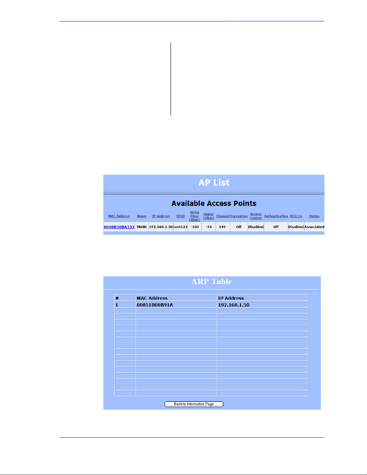
AP List (CPE only)
This window displays information about the access points associated with the CPE
and the connection statistics.
You can set an access point‘s SSID as your primary SSID by clicking on the MAC
address when it‘s displayed as a link. This will automatically reboot the radio.
ARP Table
This table lists the devices that have attempted communication with your device
via TCP. There should be a limited number of entries in this table, especially if the
interstation blocking is turned on at the access point.
TR-5A Series
Pitt Meadows, B.C. Canada V3Y 2V4
222222
This document is intended for Public Distribution
19473 Fraser Way,
3-22
Page 39
Tranzeo Wireless Technologies
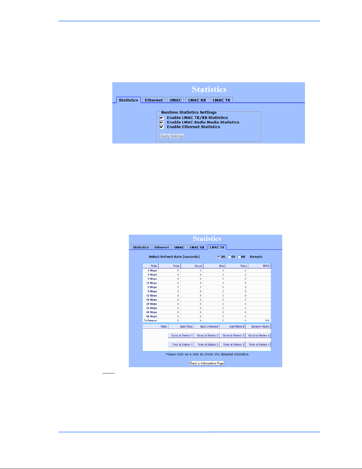
Statistics
This section is divided in 3 windows: LMAC (Lower Mac), UMAC (Upper Mac),
and Ethernet, which can be accessed from the Statistic Summary Page.
LMAC vs UMAC Statistics
The LMAC functions occur in the radio chipset. While the UMAC divides the
statistics into clean and failed packets, LMAC defines why packets failed.
You can click onto each speed level and see how the traffic breaks down. In the
TX statistics, there should little to no Tries at Series 2, 3 or 4. The radio will try to
send a packet 4 times at Series 1 and then will try the next series 4 times. In the
RX statistics, you should look for bad CRCs and bad decrypts for signs of RF
interference or Fresnel interference links. Bad PHYs generally are caused when
the radio is unable to decode the packets due to noise.
Note:
Communication between Access Points and CPEs always occurs at the lowest
rate. In a normal link, you should see a fair number of transactions at the lowest
rate.
Chapter 3: Configuration
TR-5A Series
Pitt Meadows, B.C. Canada V3Y 2V4
232323
This document is intended for Public Distribution
19473 Fraser Way,
3-23
Page 40
Tranzeo Wireless Technologies
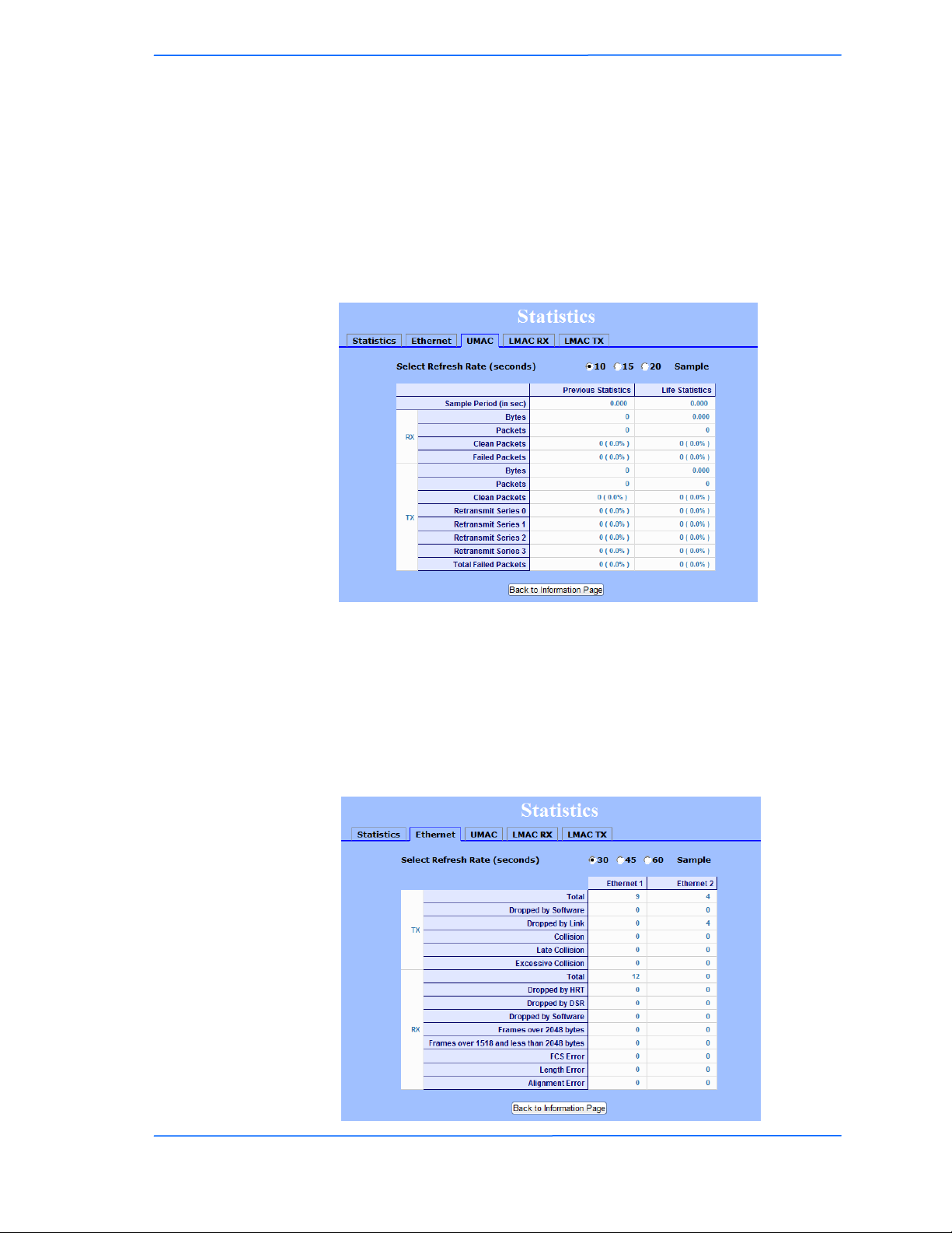
UMAC Statistics
The UMAC functions occur in the unit‘s processor. The UMAC statistics are
likely the most useful for radio troubleshooting. This window breaks down the
statistics into clean and failed packets.
The failed packets should be less than 10% in a normal operating environment. In
the TX statistics, there should be little to no Retransmits at Series 2, 3 or 4. Life
Statistics are reset on each reboot.
Chapter 3: Configuration
Ethernet Statistics
In this window, excessive collisions are usually a sign that the radio and the device
it is linked to are not on the same duplex settings. One is at full while the other is
at half. Try locking both to the same values.
Collisions do normally occur on an Ethernet network and are generally handled by
the Carrier Sense Multiple Access with Collision Detect (CSMA/CD) mechanism.
Alignment, length and excessive FCS errors could the result of a bad radio link, or
a bad Ethernet cable.
TR-5A Series
Pitt Meadows, B.C. Canada V3Y 2V4
242424
This document is intended for Public Distribution
19473 Fraser Way,
3-24
Page 41
Tranzeo Wireless Technologies
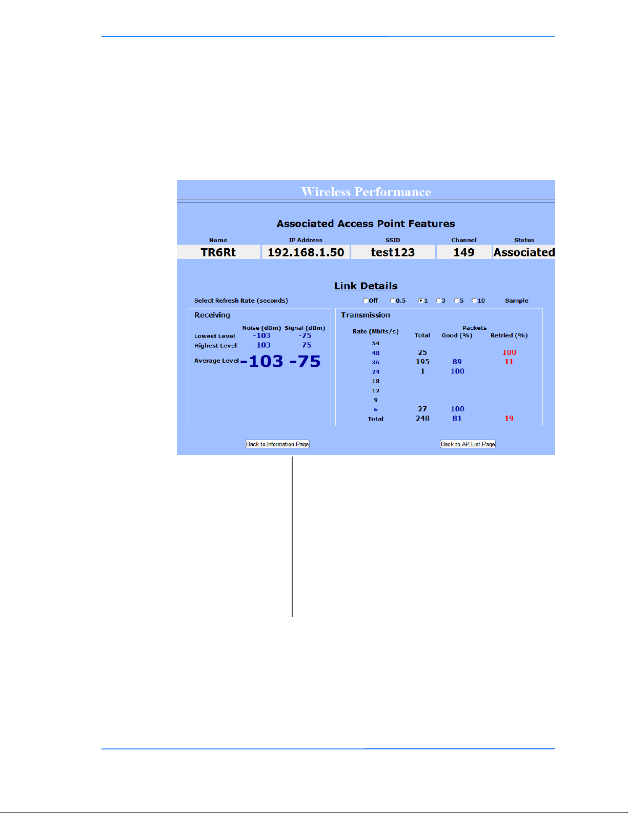
Wireless Performance (CPE only)
This window shows information about the Wireless Performance of the radio.
This window is only available in Infrastructure (CPE) Mode. Many browsers do
not allow infinite refreshes of a page through scripts, so this window may stop
updating. If it does, simply change the refresh rate to another value to restart the
process.
Chapter 3: Configuration
Associated Access
Select Refresh Rate:
Master / Slave:
Transmission:
TR-5A Series
Pitt Meadows, B.C. Canada V3Y 2V4
Shows the details of the Access Point the device is
Point:
connected to.
Set the time for automatic refreshes.
Shows the peer radio details including IP, MACs,
SSIDs, Channels. Click the IP address to bring up the
peer radio in a new browser tab.
Receiving:
Shows the lowest, average and the highest signal and
noise levels in dBm.
Shows the packet statics at each of the data rates the
radios are transmitting.
252525
This document is intended for Public Distribution
19473 Fraser Way,
3-25
Page 42
Tranzeo Wireless Technologies
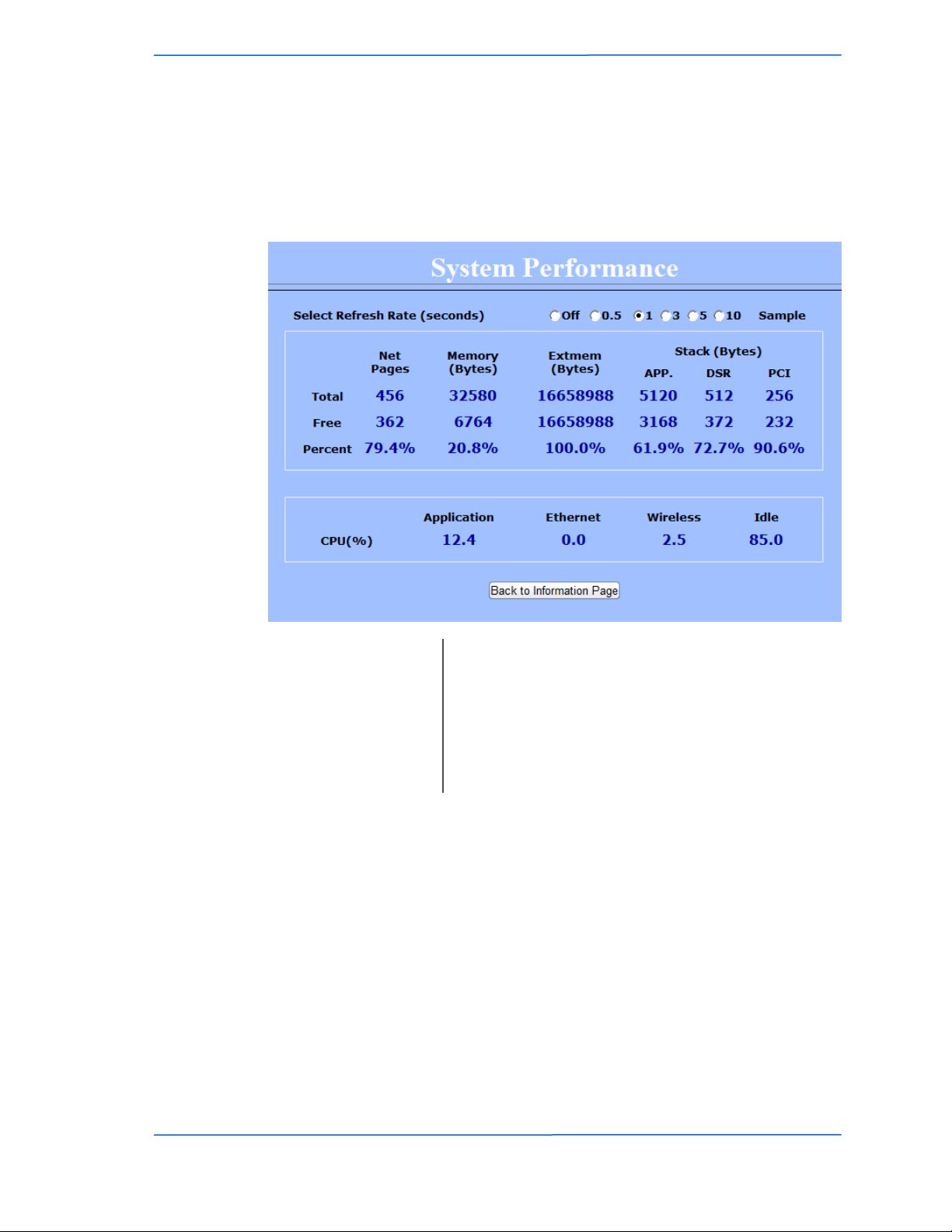
System Performance
This window shows information about the memory usage and the CPU. Many
browsers do not allow infinite refreshes of a page through scripts, so this window
may stop updating. If it does, simply change the refresh rate to another value to
restart the process.
Chapter 3: Configuration
Select Refresh Rate:
Net Pages:
Memory:
Stack:
Set the time for automatic refreshes.
This is the memory used for data transmission
This is the total memory of the system.
This section displays the memory used and available
for each stack: App. (applications), DSR, and PCI.
This information is relevant for programmers.
TR-5A Series
Pitt Meadows, B.C. Canada V3Y 2V4
262626
This document is intended for Public Distribution
19473 Fraser Way,
3-26
Page 43
Tranzeo Wireless Technologies
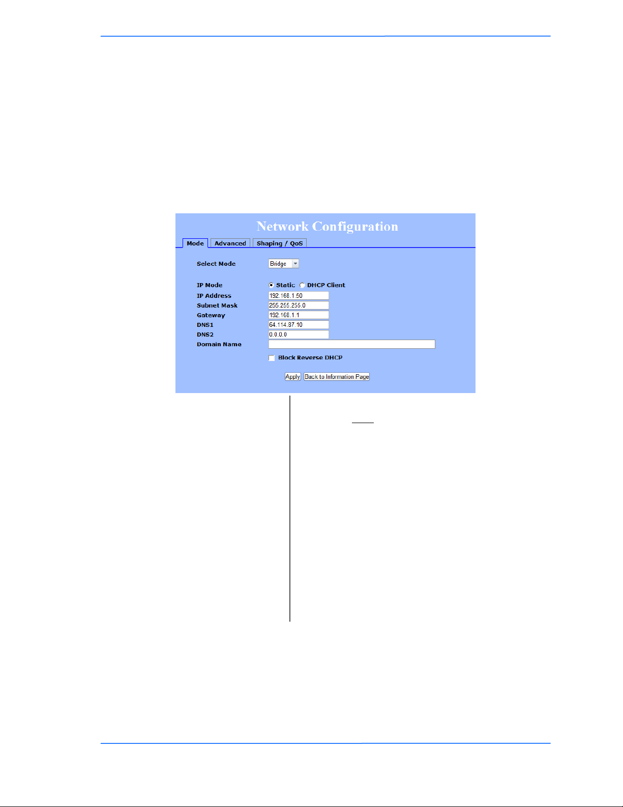
Network Configuration
In this window you can control the network configuration of the device. First, you
must define if your radio will operate as a bridge or router. The content of the
window varies depending on your selection.
When changing modes, the radio may need to reboot before certain features
become available.
Bridge Mode - Static
Block Reverse DHCP:
IP Address:
Subnet Mask:
Domain Name:
IP Mode:
Gateway:
DNS:
Chapter 3: Configuration
You can select to use Static IP or DHCP Client
(dynamic). Note: If a DHCP server is not available, the
device will try to get an IP for 30 seconds after which
it will use the fallback IP address. The fallback IP is
the address that is set in the static address fields.
Enter the IP address of the device.
Enter the subnet mask that will be used.
Enter the gateway for this device to use.
Enter the DNS servers for this device to use.
Enter the Domain Name if required.
Stops the device from passing DHCP offers upstream.
When enabled, if a unit is accidently plugged into the
LAN port of home router or gateway, that device‘s
DHCP offers will not be transmitted into the network.
TR-5A Series
Pitt Meadows, B.C. Canada V3Y 2V4
272727
This document is intended for Public Distribution
19473 Fraser Way,
3-27
Page 44
Tranzeo Wireless Technologies
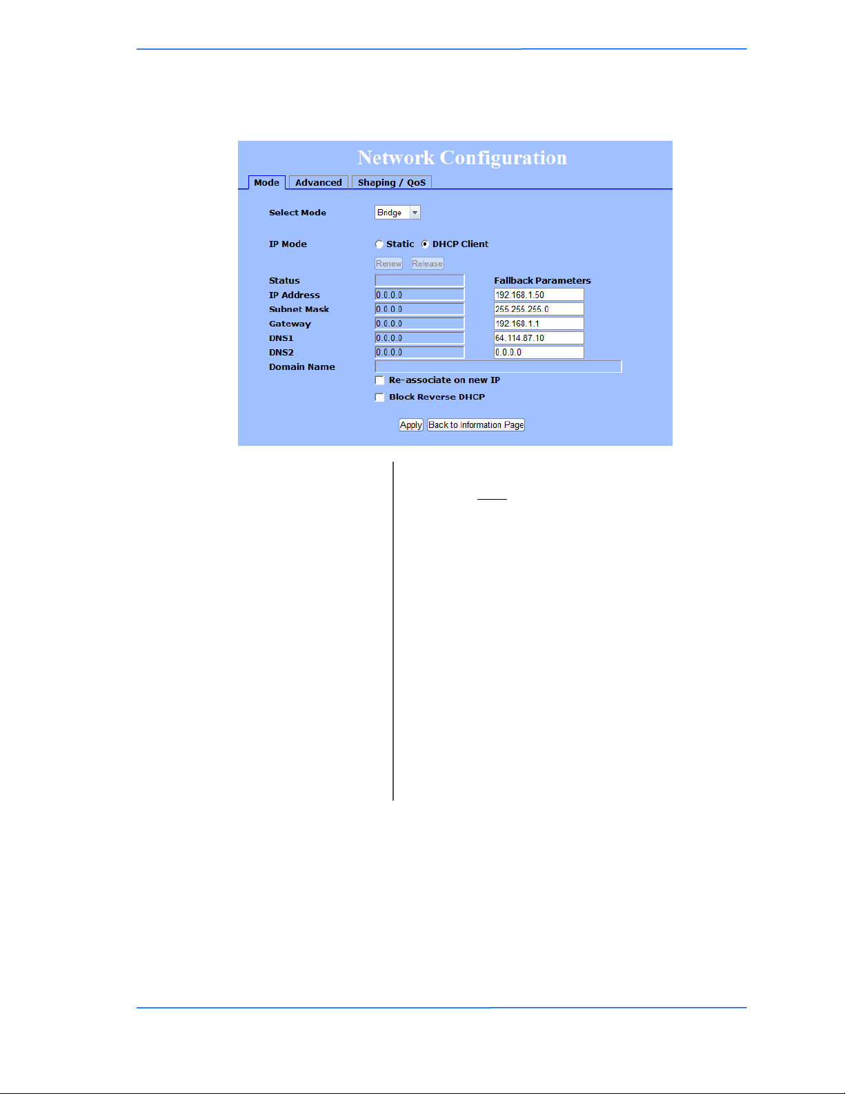
Bridge Mode - DHCP Client
Re-associate
Block Reverse DHCP:
IP Mode:
on new IP:
IP Address:
Chapter 3: Configuration
You can select to use Static IP or DHCP Client
(dynamic). Note: If a DHCP server is not available, the
device will try to get an IP for 30 seconds after which
it will use the fallback IP address. The fallback IP is
the address that is set in the static address fields.
Radio will re-associate when it gets a new IP address.
Unless advised otherwise by Tranzeo Support staff,
this option is best left off.
Stops the device from passing DHCP offers upstream.
When enabled, if a unit is accidently plugged into the
LAN port of home router or gateway, that device‘s
DHCP offers will not be transmitted into the network.
Enter the IP address of the device.
Subnet Mask:
Fallback parameters are the parameters that the radio will use if it doesn‘t receive
a response to its DHCP request.
TR-5A Series
Pitt Meadows, B.C. Canada V3Y 2V4
Enter the subnet mask that will be used.
Gateway:
DNS:
282828
This document is intended for Public Distribution
19473 Fraser Way,
Enter the gateway for this device to use.
Enter the DNS servers for this device to use.
3-28
Page 45
Tranzeo Wireless Technologies
Router Mode
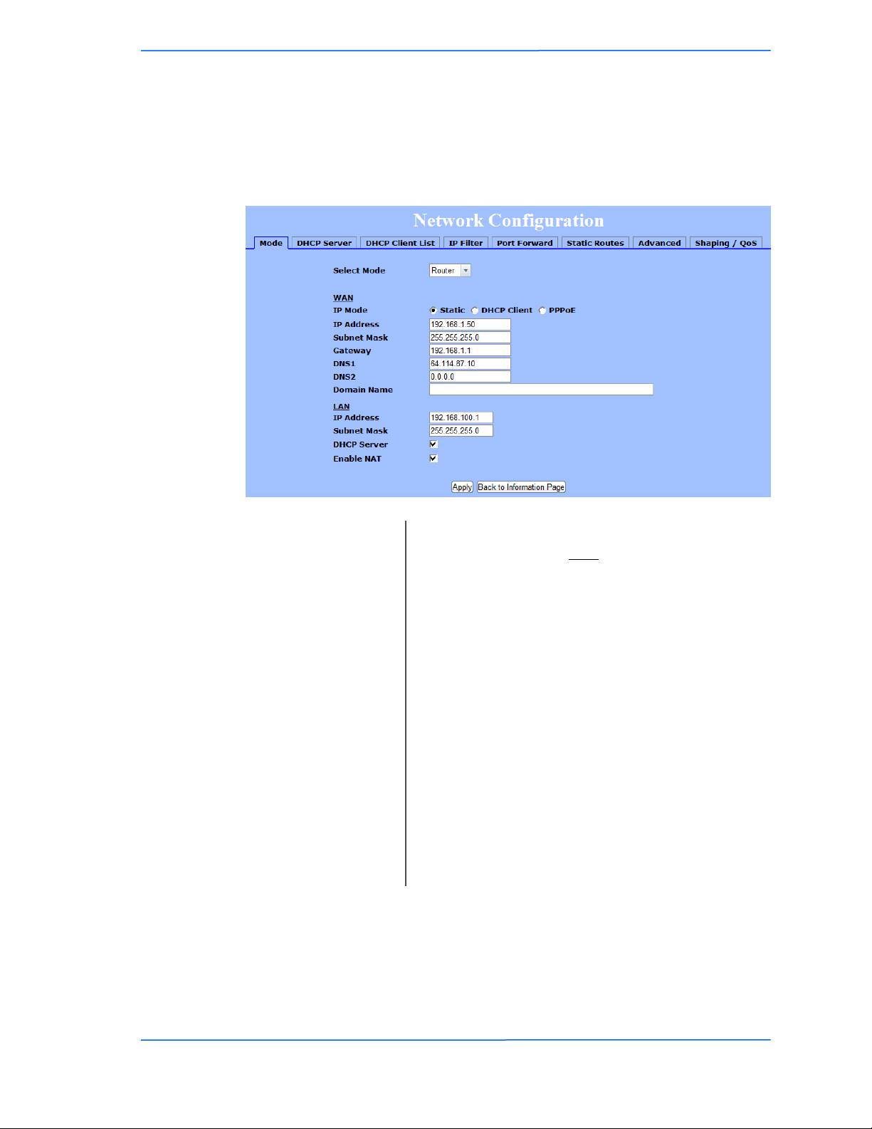
From this window you can access specific windows to configure the DHCP
Server, QoS, Static Routes, Port Filtering, and Port Forwarding. If the feature is
available, it will appear as a tab. These features are described in the next pages.
DHCP Server:
IP Mode:
WAN:
LAN:
Enable NAT:
Chapter 3: Configuration
You can select to use Static IP, DHCP Client
(dynamic), or PPPoE. Note: If a DHCP server is not
available, the device will try to get an IP for 30
seconds after which it will use the fallback IP address.
The fallback IP is the address that is set in the static
address fields.
Enter the information related to the WAN interface: IP
Address, Subnet Mask, Gateway, DNS1, DNS2, and
Domain Name.
NOTE: If you do not set at least one DNS server, the
CPE‘s DHCP clients will not
Enter the information related to the LAN interface: IP
address and subnet mask.
Check the box and click Apply to enable this feature.
Click on the item (which now appears as a link) to
open the DHCP Server configuration window.
Enables NAT. NAT should always be enabled when
using private addressing.
TR-5A Series
Pitt Meadows, B.C. Canada V3Y 2V4
292929
This document is intended for Public Distribution
19473 Fraser Way,
3-29
Page 46
Tranzeo Wireless Technologies
Router Mode - PPPoE
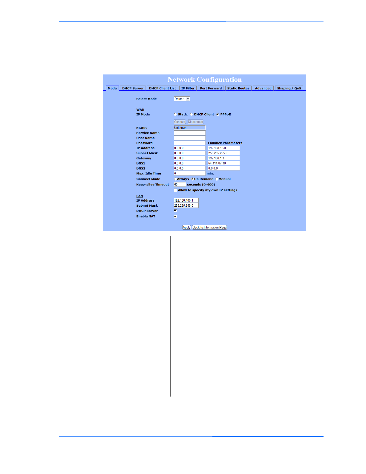
From this window you can configure your PPPoE settings.
Connect Mode:
IP Mode:
WAN:
Chapter 3: Configuration
You can select to use Static IP, DHCP Client
(dynamic), or PPPoE. Note: If a PPPoE server is not
available, the device will try to get an IP for 30
seconds after which it will use the fallback IP address.
The fallback IP is the address that is set in the static
address fields.
Enter the information related to the WAN interface: IP
Address, Subnet Mask, Gateway, DNS1, DNS2, and
Domain Name.
Select the connect mode your PPPoE setup requires.
Keep-alive Timeout:
DHCP Server:
TR-5A Series
Pitt Meadows, B.C. Canada V3Y 2V4
Timeout on the PPPoE connection in seconds. (0-600)
LAN:
Enter the information related to the LAN interface: IP
address and subnet mask.
Check the box and click Apply to enable this feature.
Click on the item (which now appears as a link) to
open the DHCP Server configuration window.
Enable NAT:
Enables NAT. NAT should always be enabled when
using private addressing.
303030
This document is intended for Public Distribution
19473 Fraser Way,
3-30
Page 47
Tranzeo Wireless Technologies
Networking Advanced
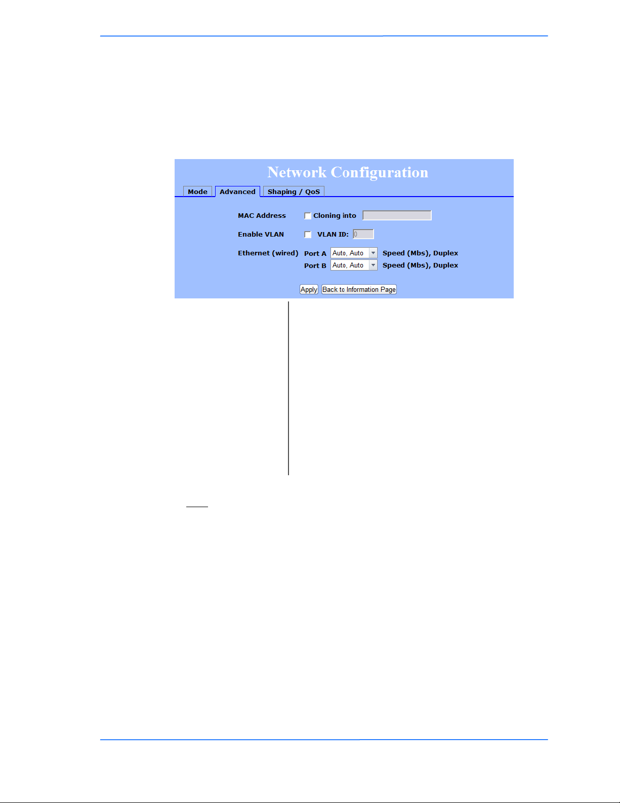
In this tab you can configure the advanced networking settings. There are
different options if you are in Bridge or Router mode.
Bridge Mode
Cloning MAC Address:
Ethernet Port Speed:
* Enabling VLAN will make the radio only accessible on the defined VLAN.
**Note:
Many Ethernet devices do not auto-negotiate properly. If you see large numbers of
dropped pings, you may have collisions. Try locking the device at 10/half as a
troubleshooting step. If the packet losses stop, step up to 100/full. If the device the
radio is connecting to cannot support 100/full, you should replace the device or
place a switch in line.
Enable VLAN:
Chapter 3: Configuration
This feature allows the radio to copy the MAC address
of the device you have connected to the network. This
is useful when you change your device and don‘t want
to register a new MAC address, or when dealing with
some PPPoE and Radius implementations. To clone a
MAC address, check the MAC Address box and enter
the MAC address in the field Cloning into. Uncheck
to restore the original MAC address.
NOTE: When the device is cloning a MAC address, it
can only be managed from the LAN side.
Enables and sets the management VLAN on the radio.
Set as Auto by default.**
TR-5A Series
Pitt Meadows, B.C. Canada V3Y 2V4
313131
This document is intended for Public Distribution
19473 Fraser Way,
3-31
Page 48
Tranzeo Wireless Technologies
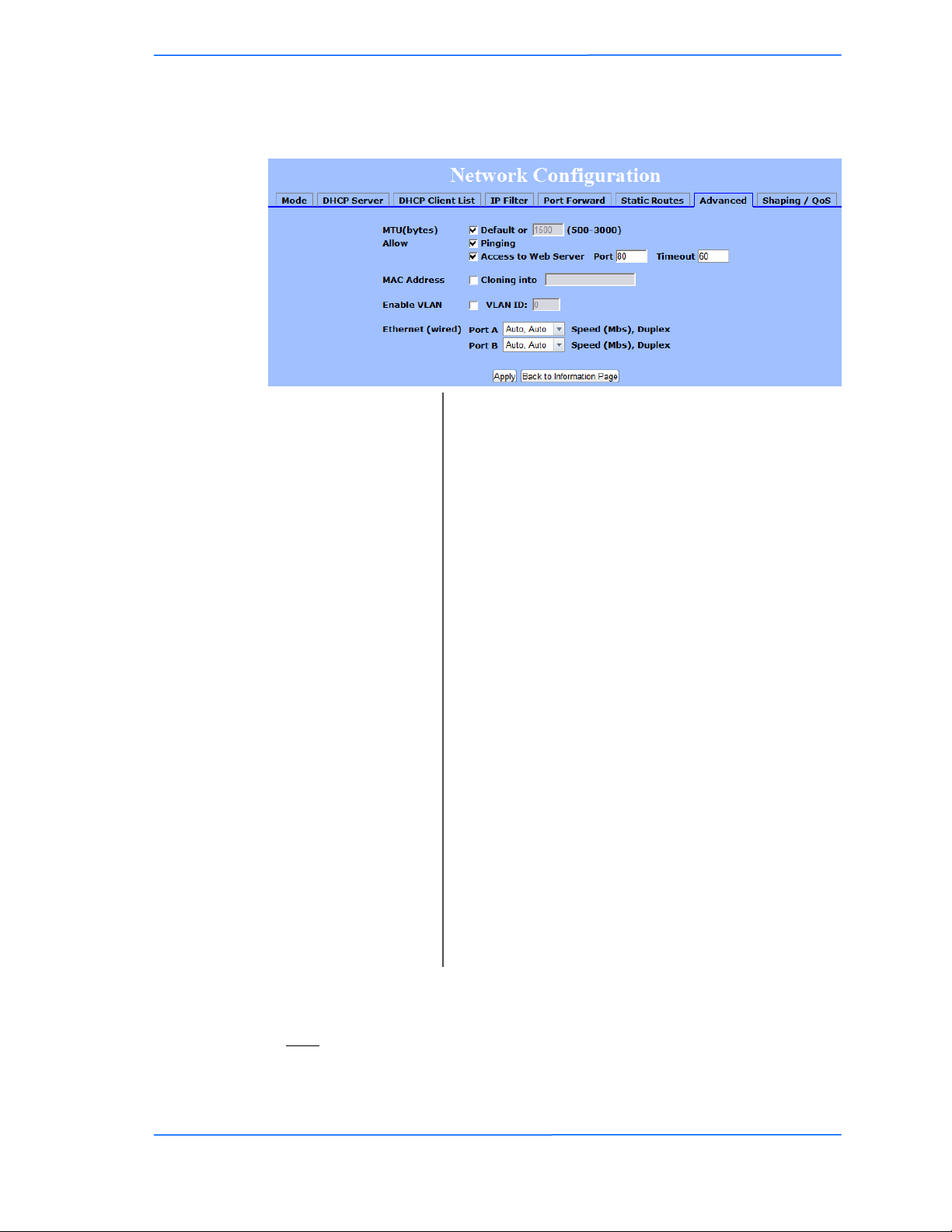
Advanced Router Mode
Allow Pinging:
MTU:
Chapter 3: Configuration
The Maximum Transmission Unit (MTU) refers to the
size of the largest packet that the router can pass. The
default value is 1500 bytes. If PPPoE is used, you
should change the MTU to match the PPPoE server,
typically 1492 bytes.
HINT: For maximum throughput, try setting the
MTU to 1460. This matches the payload size of an
802.11 RF packet and can have a large impact on
overall throughput.
Enables ping responses on WAN interface.
Allow Access to Web
Server:
Allows access from WAN interface or change the port
the WAN server responds to web server requests.
NOTE:: Access to web server from LAN interface is
always enabled and set at port 80.
Cloning MAC Address:
This feature allows the radio to copy the MAC address
of the device you have connected to the network. This
is useful when you change your device and don‘t want
to register a new MAC address, or when dealing with
some PPPoE and Radius implementations. To clone a
MAC address, check the MAC Address box and enter
the MAC address in the field Cloning into. Uncheck
to restore the original MAC address.
NOTE: When the device is cloning a MAC address, it
can only be managed from the LAN side.
Enable VLAN*:
Ethernet Port Speed**:
Enables and sets the management VLAN on the radio.
Set as Auto by default.**
* Enabling VLAN will make the radio only accessible on the defined VLAN.
**Note:
Many Ethernet devices do not auto-negotiate properly. If you see large numbers of
dropped pings, you may have collisions. Try locking the device at 10/half as a
troubleshooting step. If the packet losses stop, step up to 100/full. If the device the
TR-5A Series
Pitt Meadows, B.C. Canada V3Y 2V4
323232
This document is intended for Public Distribution
19473 Fraser Way,
3-32
Page 49
Tranzeo Wireless Technologies
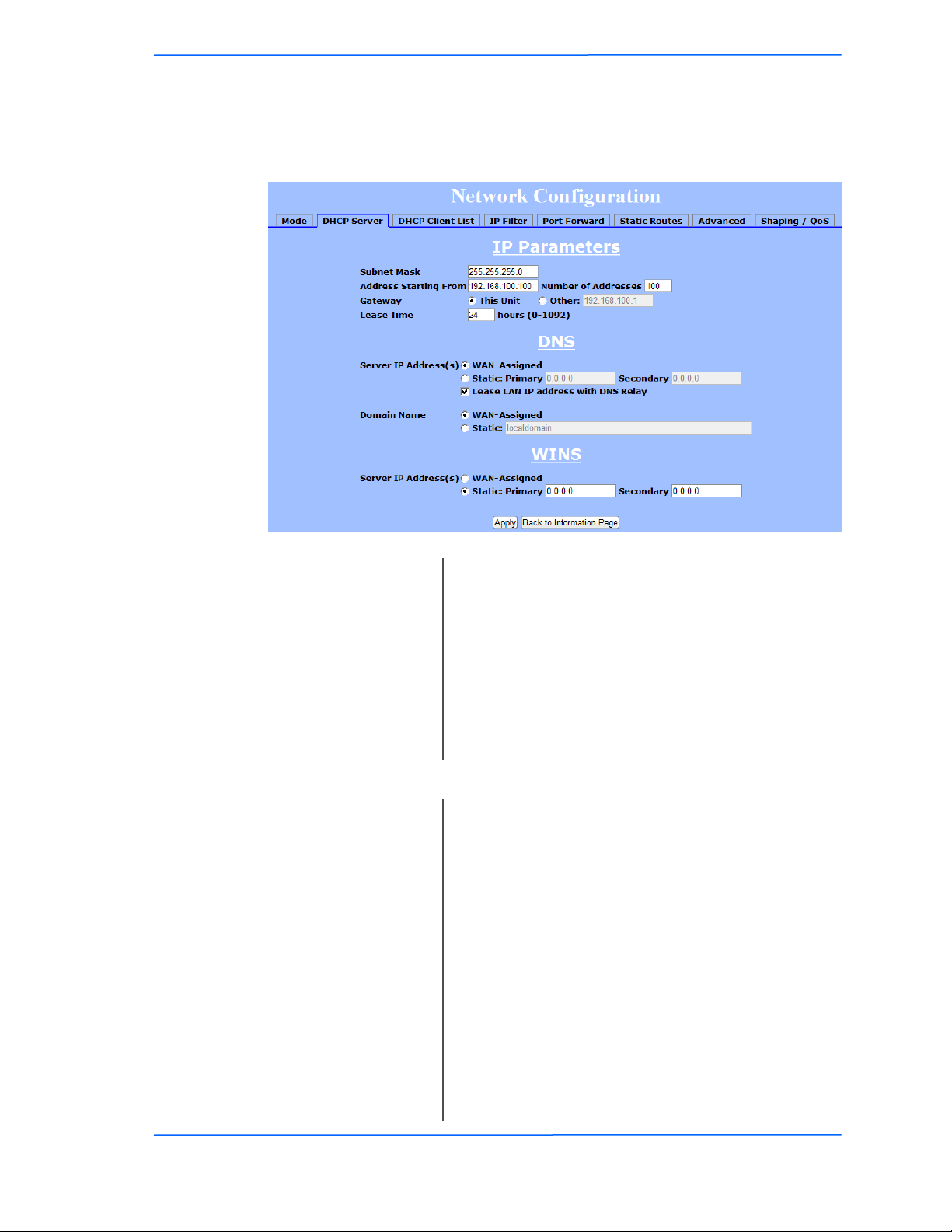
DHCP Configuration
This window shows the configuration of the DHCP server.
Chapter 3: Configuration
IP Parameters
Subnet Mask:
Address Starting from:
Number of Addresses:
Gateway:
Lease Time:
DNS
Server IP Address:
Domain Name:
Enter your subnet mask in this field.
Indicates the first address in the DHCP pool.
Indicates the number of addresses in the DHCP pool.
*Note* TR-SL5 is limited to 10 addresses
Select This Unit to use the gateway set on the WAN
interface. Select Other to use a different gateway.
Indicates the expiration time for the IP address
assigned by the DHCP server.
Select WAN Assigned to use the DNS server IP
addresses assigned on the Mode tab under WAN. To
use different DNS servers, select Static, in which case
you must enter the Primary and Secondary IP
addresses.
NOTE: If you select WAN-Assigned, you must have
at least one DNS server entered in the MODE tab.
Select WAN Assigned to use the Domain name
assigned on the Mode tab under WAN. To use a
different domain name select Static, and enter the
domain name.
TR-5A Series
Pitt Meadows, B.C. Canada V3Y 2V4
WINS:
Select WAN Assigned to use the WINS Address
assigned on the Mode tab under WAN. To use a
different WINS Server select Static, and enter the IP
address of the WINS Server.
333333
This document is intended for Public Distribution
19473 Fraser Way,
3-33
Page 50
Tranzeo Wireless Technologies
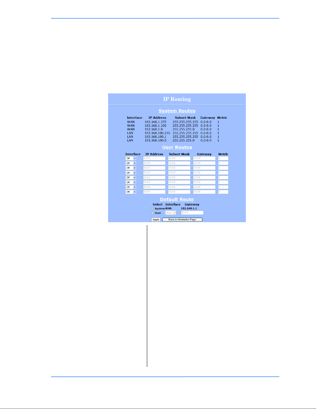
IP Routing
This window is intended for those users who have a strong understanding of IP
routing. Here you can see the System Routes, create your User Routes, and set the
Default Route.
IMPORTANT! Be careful when making changes since misconfiguration could
!!
result in serious network problems and even the loss of functionality.
Chapter 3: Configuration
Subnet Mask:
Default Route:
TR-5A Series
Pitt Meadows, B.C. Canada V3Y 2V4
Interface:
IP Address:
Gateway:
Metric:
343434
This document is intended for Public Distribution
19473 Fraser Way,
Specify if the interface is WAN or LAN. Select Off to
disable the route.
This is the IP address or network that the packets will
be attempting to access.
Specifies the part of the destination IP that represents
the network address and the part that represents the
host address. Note: 255.255.255.255 represents only
the host entered in the Destination IP field.
Indicates the next hop if this route is used. A gateway
of 0.0.0.0 means there is no next hop and the IP
address matched is directly connected to the router on
the interface specified.
This is the number of hops it will take to reach the
destination. A hop occurs each time data passes
through a router from one network to another. If there
is only one router between your network and the
destination network, then the metric value would be 1.
This option allows you to change the default route of
the radio. Make changes with extreme caution.
3-34
Page 51
Tranzeo Wireless Technologies
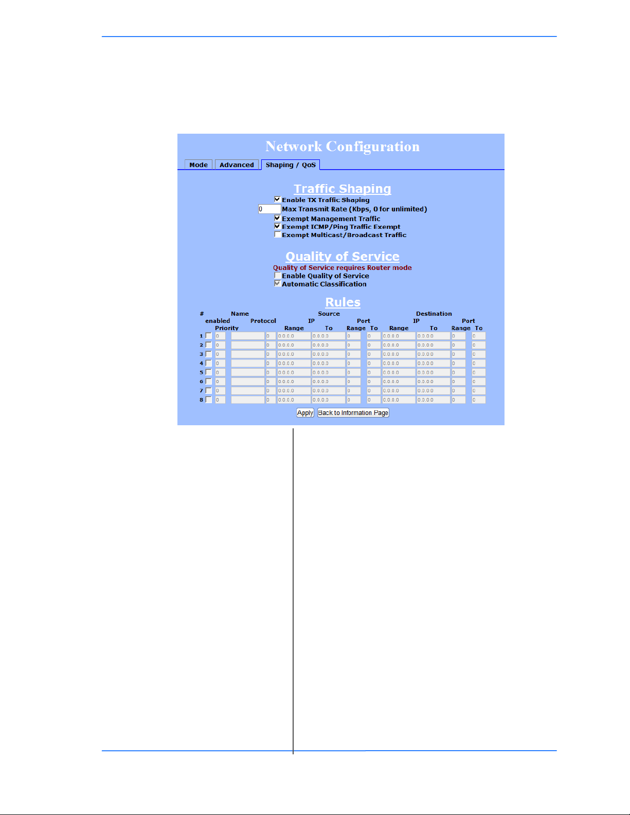
Shaping and Quality of Service Configuration (QoS)
In this window you can use the shaping and QoS features and set rules to
prioritize the traffic.
Chapter 3: Configuration
Enable Traffic
Shaping:
Max Transmit Rate:
Exempt Management
Traffic:
Exempt ICMP/Ping
Traffic:
Exempt Multicast/
Broadcast Traffic:
Enable Quality of
Service:
Automatic
Classification:
Enabled:
Enables traffic shaping. Traffic shaping the amount of
data the Radio will send. It does affect the amount of
data the radio can receive. Receive should be
controlled at the head end of the network.
Sets the maximum rate the radio will transmit in Kbps.
Set to 0 for unlimited. In AP mode it is the aggregate
total not the per client limit.
Exempts management traffic from being limited.
Exempts ICMP and Ping traffic from being limited.
Exempts Multicast and Broadcast traffic from being
limited.
Enables Quality of Service (QOS). *Only available in
Router Mode
This feature automatically classifies traffic and gives
priority to certain applications. Applications such as
VOIP and gaming are automatically given priority.
Check to activate a rule. Most users are recommended
to use the default StreamEngine settings.
TR-5A Series
Pitt Meadows, B.C. Canada V3Y 2V4
Priority:
353535
This document is intended for Public Distribution
19473 Fraser Way,
Enter the priority of the rule between 0 and 255.
3-35
Page 52

Tranzeo Wireless Technologies
Chapter 3: Configuration
Name:
Protocol:
Source IP Range:
Source Port Range:
Destination IP Range:
Destination Port
Range:
.
Enter the name of the rule here.
Enter the protocol number here. Common options are:
0 for ANY, 1 for ICMP, 6 for TCP, and 17 for UDP.
See Appendix C for Protocol List.
Enter the range of IP addresses on the LAN side where
the rule would apply. To cover all LAN IPs, enter
0.0.0.0. For a single IP, enter the IP in both boxes.
Enter the range of ports on the LAN side where the
rule would apply. To cover all ports, enter 0. For a
single port, enter this port in both boxes.
Enter the range of IP addresses on the WAN side
where the rule would apply.
Enter the range of ports on the WAN side where the
rule would apply.
TR-5A Series
Pitt Meadows, B.C. Canada V3Y 2V4
363636
This document is intended for Public Distribution
19473 Fraser Way,
3-36
Page 53
Tranzeo Wireless Technologies
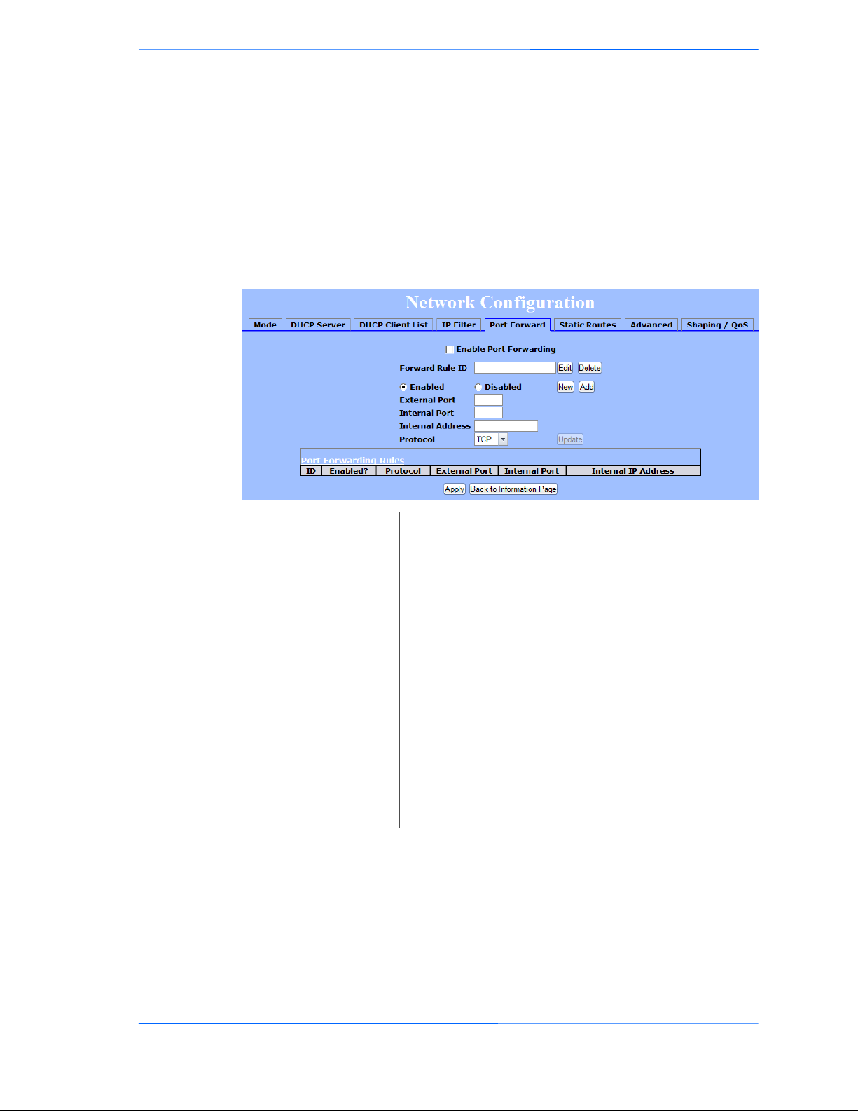
Port Forwarding
This feature allows the radio to forward requests for certain ports to devices
behind a router. For example, you have a web server on a private IP of
192.168.1.2 that you want to be accessible to the world. You can forward all
requests on port 80 to 192.168.1.2. NOTE: For this example to work, you have to
change the management port of the radio from port 80 on the Network
Configuration window.
In this window, you can create, edit, delete, and manage rules for port forwarding.
Chapter 3: Configuration
Enable Port
Forwarding:
Forward Rule ID:
Edit / Delete:
Enabled / Disabled:
External Port:
Internal Port:
Internal Address:
Protocol:
New:
Add:
Click to apply rules from the Rules list.
Enter the rule ID here to retrieve its information.
Click to modify or remove the selected rule.
Activate or deactivate the selected rule.
Enter the port to which requests will be forwarded.
Enter your port here.
Enter your IP address.
Select the protocol used for this rule.
Click to create a new rule. Fields will be cleared.
After creating a rule, click this button to include the
new rule in the Port Forwarding Rules list.
Update:
Click to apply changes after editing or deleting a rule.
A list of current port forwarding rules appears at the bottom of the page.
TR-5A Series
Pitt Meadows, B.C. Canada V3Y 2V4
373737
This document is intended for Public Distribution
19473 Fraser Way,
3-37
Page 54
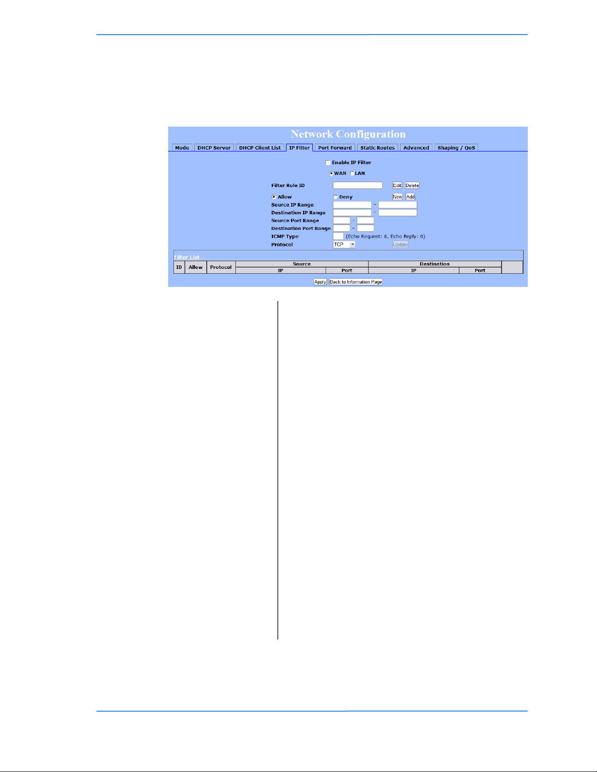
Tranzeo Wireless Technologies
IP Filtering
This feature allows the radio to block requests to and from devices behind the
router. A list of the devices filtered appears at the bottom of the window.
Chapter 3: Configuration
Enable IP Filter:
WAN / LAN:
Filter Rule ID:
Edit / Delete:
Allow / Deny:
New:
Add:
Source IP Range:
Destination IP Range:
Source Port Range:
Destination Port
Range:
ICMP Type:
Click to apply the rules enabled from the Filter list.
Select the network.
Enter the filter rule ID here to retrieve its information.
Click to modify or eliminate the selected filter.
The rule can either allow or deny ports.
Click to create a new filter. Fields will be cleared and
you may enter the information for the new filter.
After creating a filter, click this button to include the
new filter in the Filter list.
Enter the range of IP addresses on the LAN side where
the rule would apply.
Enter the range of IP addresses on the WAN side
where the rule would apply.
Enter the range of ports on the LAN side where the
rule would apply.
Enter the range of ports on the WAN side where the
rule would apply.
This allows you to block certain types of ICMP as a
prevention against port scanning and some viruses.
TR-5A Series
Pitt Meadows, B.C. Canada V3Y 2V4
Protocol:
Update:
383838
This document is intended for Public Distribution
19473 Fraser Way,
Select the protocol used for this rule.
Click to apply changes after editing or deleting a filter.
3-38
Page 55

Tranzeo Wireless Technologies
Appendix A: Grounding and Lightning
What is a proper ground?
This antenna must be grounded to a proper earth ground. According to the
National Electrical Code Sections 810-15s and 810-21, the grounding conductor
shall be connected to the nearest accessible locations of the following:
The building or structure grounding electrode
The grounded interior metal water piping system
The power service accessible means external to enclosure
The metallic power service raceway
The service equipment enclosure
The grounding electrode conductor
Appendix A
Protection Information
Why is coiling the LMR or Cat 5 bad?
The myth is that lighting follows the path of least resistance. It actually follows the
path of least impedance. Coiling cables creates an air-wound transformer, which
lowers the impedance. This means you are in fact making your radios a more
appealing target for surges.
What standard does Tranzeo Wireless equipment meet?
This radio exceeds International Standard IEC 61000-4-5 when properly
grounded. For a copy of the full testing report, see Report Number TRL090904 Tranzeo Surge Protection board located on the Tranzeo website
(www.tranzeo.com).
Is lightning damage covered by the warranty?
No. Lightning is not covered by the warranty. If you follow the instructions, your
chances of lightning damage are greatly reduced, but nothing can protect a radio
from a direct lightning strike.
TR-5A Series
Pitt Meadows, B.C. Canada V3Y 2V4
111
This document is intended for Public Distribution
19473 Fraser Way,
A-1
Page 56
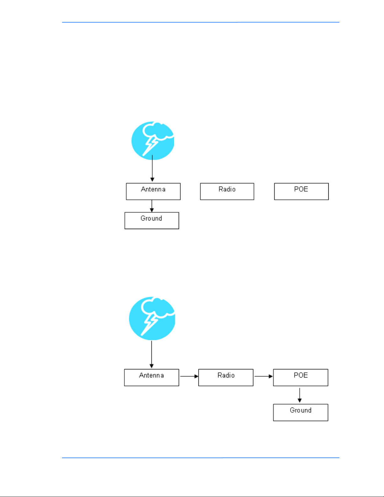
Tranzeo Wireless Technologies
Where to ground the device?
This radio must be grounded at the pole and at the POE. This is because the radio
is between the exterior antenna and the POE ground. See the examples below.
Grounded Radio
A grounded radio causes the surge to pass directly to ground, bypassing the radio.
Appendix A
Ungrounded Radio
An ungrounded radio causes the surge to pass through the radio. In this case, the
radio most likely will be damaged.
TR-5A Series
Pitt Meadows, B.C. Canada V3Y 2V4
222
This document is intended for Public Distribution
19473 Fraser Way,
A-2
Page 57
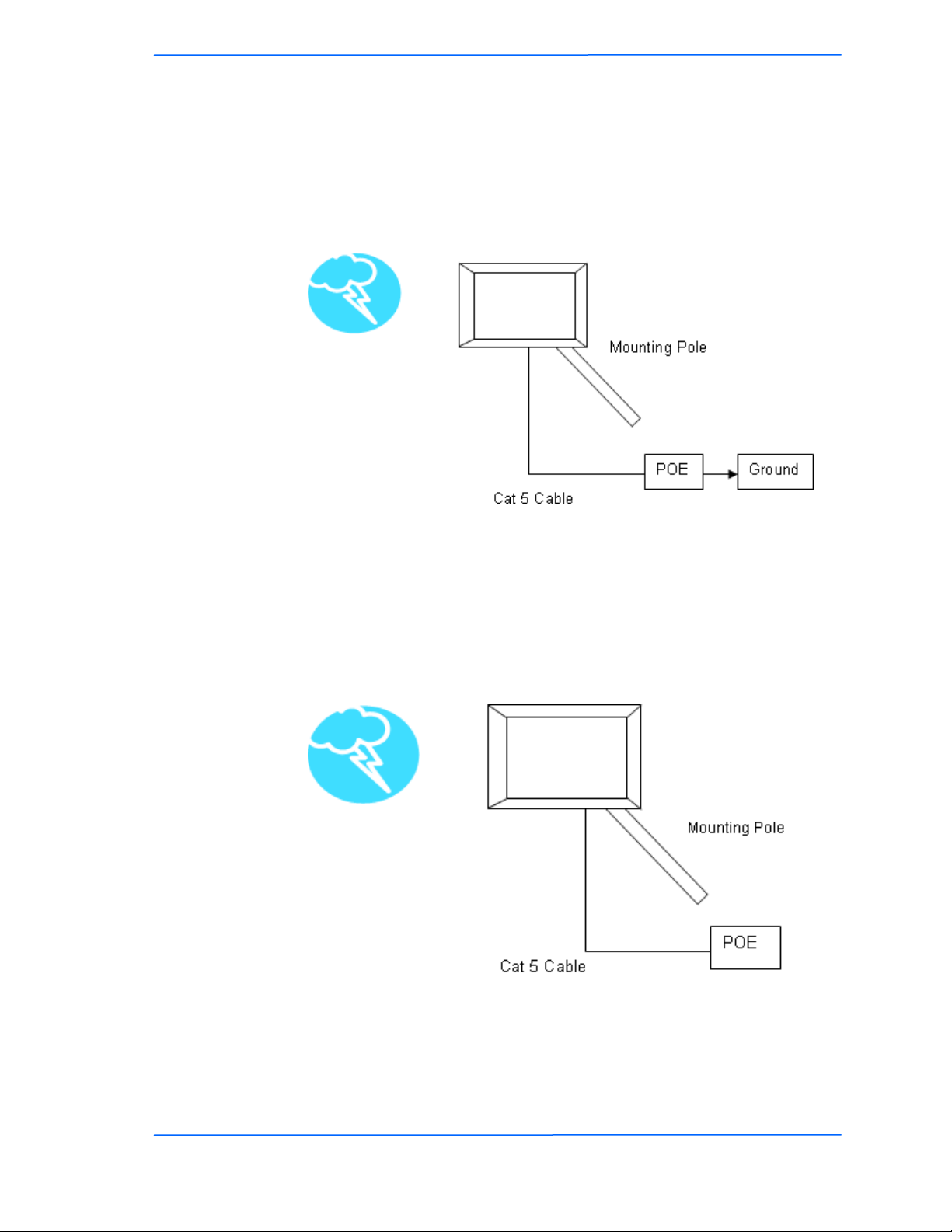
Tranzeo Wireless Technologies
Grounded POE
In this case, the surge will be picked up by the Cat 5 cable and since the POE is
grounded, the route for the surge is through the POE to ground.
Appendix A
Ungrounded POE
In this case, the surge will be picked up by the Cat 5 cable and since the POE is
not grounded, the route for the surge is through the radio to the antenna, and out
through the building.
TR-5A Series
Pitt Meadows, B.C. Canada V3Y 2V4
333
This document is intended for Public Distribution
19473 Fraser Way,
A-3
Page 58

Tranzeo Wireless Technologies
Tranzeo Wireless Technologies‘ software ensures a consistently high quality
online experience through the use of powerful Quality of Service (QoS)
mechanisms. The key to making this applicable in a WISP environment is the
Intelligent Stream Handling, a patent-pending algorithm that autonomously
manages the flow of traffic going to the Internet without the need for user
configuration. As a result, real-time, interactive traffic—such as gaming, VoIP,
and video teleconferencing—is automatically given the appropriate priority when
other users and applications use the connection. In addition, Intelligent Stream
Handling minimizes the impact of large packet, lower priority traffic on latencysensitive traffic and eliminates delays. Tranzeo software effectively eliminates the
lag and breakup problem in online gaming and other voice and video applications.
In today's broadband environment, the impact of just one data stream running in
parallel with a real-time application can be quite dramatic. Using NetIQ's Chariot
VoIP test measurement over a connection, it can be demonstrated that introducing
a single FTP transfer in the upstream direction will reduce the Mean Opinion
Score (MOS) for a G.729 VoIP codec from a very good 4.4 to a completely
unacceptable level of 1 immediately. Using the same scenario with Tranzeo‘s QoS
enabled, the voice quality remains consistently high with an MOS of 4.4, and
maintains that level even with multiple FTP streams.
Appendix B: Quality of Service
Appendix B
Configuration (QoS)
Automatic Traffic Classification
Tranzeo software has the capability of continually monitoring and classifying
traffic on the Internet connection, and dynamically adjusting the way individual
streams are handled at any point in time. This enables latency-sensitive traffic—
such as voice, games, or even web page requests— to be given a relatively high
priority. As a result, these packets are sent to their destination first, reducing delay
and jitter. Less time-sensitive traffic—such as email or file transfers—are sent at
lower priority. Since Intelligent Stream Handling operates automatically without
the need for user configuration, it is able to effectively use 255 priority levels for
fine-grained control of the packet streams.
Rate Matching
A process called "rate matching" determines the bandwidth of the broadband
uplink automatically so that it can shape the traffic to smooth the flow between the
router and the Internet. This eliminates the potential bottlenecks and delays that
can be caused by "bursty" data traffic.
Dynamic and Adaptive Link Fragmentation
Low priority traffic is also fragmented to reduce the latency and jitter that can be
introduced by long packets. Intelligent Stream Handling adjusts the fragment size
based on the uplink speed and also stops fragmenting long packets when no
latency-sensitive traffic is waiting to be sent, to improve the overall efficiency of
the broadband link and ensure voice can sustain a high MOS rating.
TR-5A Series
Pitt Meadows, B.C. Canada V3Y 2V4
111
This document is intended for Public Distribution
19473 Fraser Way,
B-1
Page 59
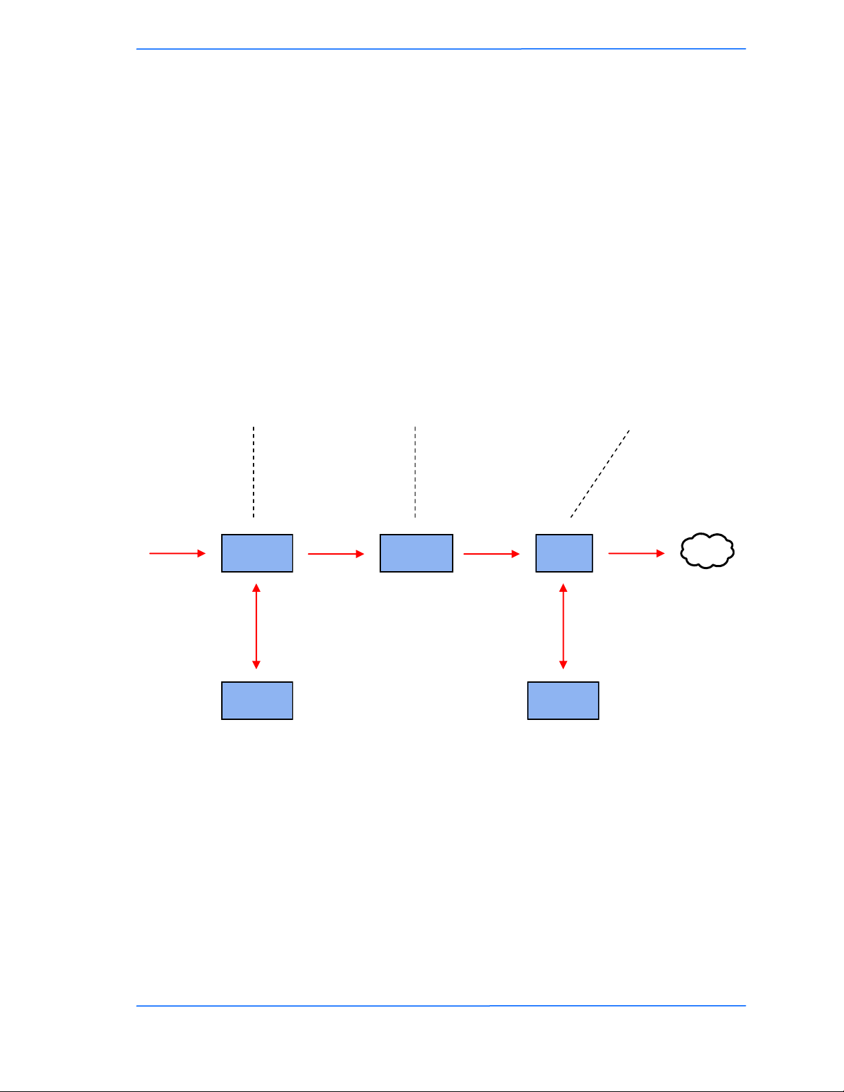
Tranzeo Wireless Technologies
QoS Block Diagram
Tranzeo software has the capability of
continually monitoring and classifying
traffic on the Internet connection, and
dynamically adjusting the way
individual streams are handled at any
point in time. This enables latencysensitive traffic, such as voice, games
or even web page requests, to be given
a relatively high priority. As a result,
they are sent to their destination first,
reducing delay and jitter. Less timesensitive traffic such as email or file
transfers are de-prioritized.
Appendix B
Intelligent Stream Handling
adjusts the fragment size based
on the uplink speed and also
stops fragmenting long packets
when no latency-sensitive traffic
is waiting to be sent, to improve
the overall efficiency of the
broadband link and ensure voice
can sustain a high MOS (Mean
Opinion Score) rating.
A process called "rate matching"
determines the bandwidth of the
broadband uplink automatically so
that it can shape the traffic to
smooth the flow between the router
and the Internet. This eliminates
the potential bottlenecks and delays
that can be caused by "bursty" data
traffic.
High Priority
Automatic
Classification
Non-latency-
sensitive traffic
High Priority High Priority
Dynamic
Fragmentation
Matching
Low-priority or
Queue Queue
Rate
excess traffic
High Priority
Internet
TR-5A Series
Pitt Meadows, B.C. Canada V3Y 2V4
222
This document is intended for Public Distribution
19473 Fraser Way,
B-2
Page 60
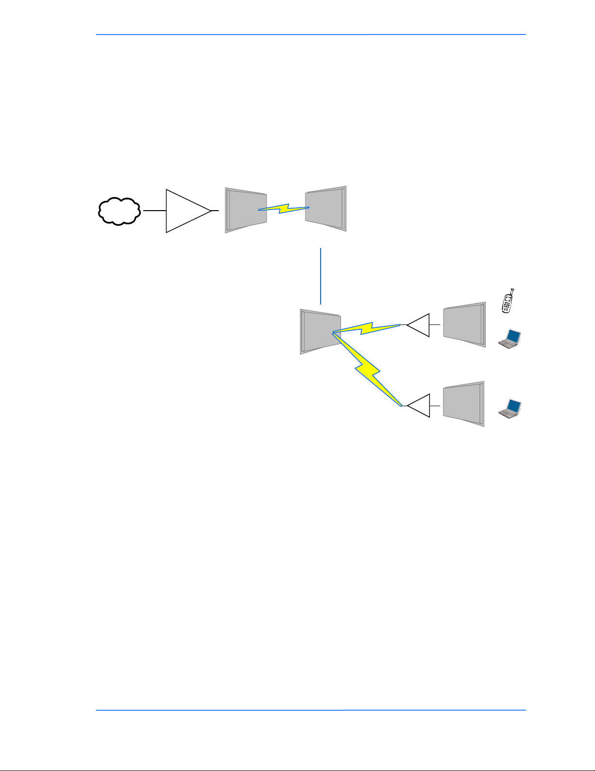
Tranzeo Wireless Technologies
Network QoS Example
Bandwidth
Internet
Shaper
Appendix B
In this case, no user is ever
able to draw more than their
fair share of the available up
stream bandwidth, even if the
communication is between
two stations on the same
30 MB
access points.
In this case, the head end
shaper is limiting the
incoming demand based on
the end user to ensure no
user is taking the entire
downstream.
5A PxP
5A PxP
6000 AP
Shaped to 1 MB
Shaped to 2 MB
QoS
QoS
6000 CPE
6000 CPE
VOIP
Computer
Computer
TR-5A Series
Pitt Meadows, B.C. Canada V3Y 2V4
333
This document is intended for Public Distribution
19473 Fraser Way,
B-3
Page 61

Tranzeo Wireless Technologies
Appendix C
Appendix C: Protocol List
Dec Keyword Protocol
0 HOPOPT IPv6 Hop-by-Hop Option
1 ICMP Internet Control Message
2 IGMP Internet Group Management
3 GGP Gateway-to-Gateway
4 IP IP in IP (encapsulation)
5 ST Stream
6 TCP Transmission Control
7 CBT CBT
8 EGP Exterior Gateway Protocol
9 IGP private interior gateway
10 BRM BBN RCC Monitoring
11 NVP-II Network Voice Protocol
12 PUP PUP
13 ARGUS ARGUS
14 EMCON EMCON
15 XNET Cross Net Debugger
16 CHAOS Chaos
17 UDP User Datagram
18 MUX Multiplexing
19 DCN-MEAS DCN Measurement
20 HMP Host Monitoring
21 PRM Packet Radio Measurement
22 XNS-IDP XEROX NS IDP
23 TRUNK-1 Trunk-1
24 TRUNK-2 Trunk-2
25 LEAF-1 Leaf-1
26 LEAF-2 Leaf-2
27 RDP Reliable Data Protocol
28 IRTP Internet Reliable Transaction
29 ISO-TP4 ISO Transport Class 4
30 NETBLT Bulk Data Transfer
31 MFE-NSP MFE Network Services
32 MERIT-INP MERIT Internodal Protocol
33 SEP Sequential Exchange
34 3PC Third Party Connect
35 IDPR Inter-Domain Policy Routing Protocol
36 XTP XTP
37 DDP Datagram Delivery
38 IDPR-
CMTP
39 TP++ TP++ Transport Protocol
40 IL IL Transport Protocol
41 IPv6 Ipv6
42 SDRP Source Demand Routing
43 IPv6-Route Routing Header for IPv6
44 IPv6-Frag Fragment Header for IPv6
45 IDRP Inter-Domain Routing
46 RSVP Reservation Protocol
47 GRE General Routing Encapsulation
48 MHRP Mobile Host Routing Protocol
49 BNA BNA
50 ESP Encap Security Payload for IPv6
IDPR Control Message Transport Proto
Dec Keyword Protocol
51 AH Authentication Header for IPv6
52 I-NLSP Integrated Net Layer Security
53 SWIPE IP with Encryption
54 NARP NBMA Address Resolution
55 MOBILE IP Mobility
56 TLSP Transport Layer Security using
Kryptonet key management
57 SKIP SKIP
58 IPv6-ICMP ICMP for IPv6
59 IPv6-NoNxt No Next Header for IPv6
60 IPv6-Opts Destination Options for IPv6
61 any host internal protocol
62 CFTP CFTP
63 any local network
64 SAT-EXPAK SATNET and Backroom EXPAK
65 KRYPTOLAN Kryptolan
66 RVD MIT Remote Virtual Disk
67 IPPC Internet Pluribus Packet Core
68 any distributed file system
69 SAT-MON SATNET Monitoring
70 VISA VISA Protocol
71 IPCV Internet Packet Core Utility
72 CPNX Computer Protocol Network Executive
73 CPHB Computer Protocol Heart Beat
74 WSN Wang Span Network
75 PVP Packet Video Protocol
76 BR-SAT-MON Backroom SATNET Monitoring
77 SUN-ND SUN ND PROTOCOL-Temporary
78 WB-MON WIDEBAND Monitoring
79 WB-EXPAK WIDEBAND EXPAK
80 ISO-IP ISO Internet Protocol
81 VMTP VMTP
82 SECURE-VMTP SECURE-VMTP
83 VINES VINES
84 TTP TTPord Protocol
85 NSFNET-IGP NSFNET-IGP
86 DGP Dissimilar Gateway Protocol
87 TCF TCF
88 EIGRP EIGRP
89 OSPFIGP OSPFIGP
90 Sprite-RPC Sprite RPC Protocol
91 LARP Locus Address Resolution
92 MTP Multicast Transport Protocol
93 AX.25 AX.25 Frames
94 IPIP P-within-IP Encapsulation
95 MICP Mobile Internetworking Control
96 SCC-SP Semaphore Communications Sec.
97 ETHERIP Ethernet-within-IP Encapsulation
98 ENCAP Encapsulation Header
99 any private encryption scheme
100 GMTP GMTP
TR-5A Series
Pitt Meadows, B.C. Canada V3Y 2V4
111
This document is intended for Public Distribution
19473 Fraser Way,
C-1
Page 62

Tranzeo Wireless Technologies
Appendix C
Dec Keyword Protocol
101 IFMP Ipsilon Flow Management
102 PNNI PNNI over IP
103 PIM Protocol Independent Multicast
104 ARIS ARIS
105 SCPS SCPS
106 QNX QNX
107 A/N Active Networks
108 IPComp IP Payload Compression
109 SNP Sitara Networks Protocol
110 Compaq-Peer Compaq Peer Protocol
111 IPX-in-IP IPX in IP
112 VRRP Virtual Router Redundancy
113 PGM PGM Reliable Transport
114 any 0-hop protocol
115 L2TP Layer Two Tunneling Protocol
116 DDX D-II Data Exchange (DDX)
117 IATP Interactive Agent Transfer
118 STP Schedule Transfer Protocol
119 SRP SpectraLink Radio Protocol
120 UTI UTI
Dec Keyword Protocol
121 SMP Simple Message Protocol
122 SM SM
123 PTP Performance Transparency
124 ISSIS ISIS over IPv4
125 FIRE
126 CRTP Combat Radio Transport
127 CRUDP Combat Radio User Datagram
128 SSCOPMCE
129 IPLT
130 SPS Secure Packet Shield
131 PIPE Private IP Encapsulation within IP
132 SCTP Stream Control Transmission
133 FC Fibre Channel
134 RSVP-E2E-IGNORE
135 Mobility header
136 UDPLite
137 MPLS-in-IP
138-252 Unassigned
253 Use for experimentation and testing
254 Use for experimentation and testing
255 Reserved
TR-5A Series
Pitt Meadows, B.C. Canada V3Y 2V4
222
This document is intended for Public Distribution
19473 Fraser Way,
C-2
Page 63

Tranzeo Wireless Technologies
Visit http://www.iana.org/assignments/port-numbers for a full list of well known
port numbers.
Appendix D
Appendix D: Common TCP Ports
Keyword Port Description
ECHO 7 Echo
SYSTAT 11 Active Users
QOTD 17 Quote of the day
MSP 18 Message Send Protocol
FTP-DATA 20 File Transfer (Data Channel)
FTP 21 File Transfer (Control)
TELNET 23 Telnet
SMTP 25 Simple Mail Transfer
NAME 42 TCP Nameserver
BOOTPS 67 Bootstrap Protocol Server
BOOTPC 68 Bootstrap Protocol Client
TFTP 69 Trivial File Transfer
WWW 80 World Wide Web
KERBEROS 88 Kerberos
POP3 110 TCP post office
NNTP 119 USENET
NFS 2049 Network File System
SIP 5060, 5061 SIP
TR-5A Series
Pitt Meadows, B.C. Canada V3Y 2V4
111
This document is intended for Public Distribution
19473 Fraser Way,
D-1
Page 64

Tranzeo Wireless Technologies
The following tables list the channel numbers and center frequencies used for
802.11a. Note that while all of these frequencies are in the unlicensed ISM and UNII bands, not all channels are available in all countries. Many regions impose
restrictions on output power as well as indoor and outdoor use on some channels.
These regulations are rapidly changing, so always check your local regulations
before transmitting.
These tables show the center frequency for each channel. Channels are 20 MHz
wide in 802.11a.
*Note: Channels 36 through 64 not available on TR-5amp.
Channel # Center Frequency
*Channels 36 through 52 are indoor only channels
**Channels 36 through 140 require DFS/TPC. In FCC domains individual
channels can not be selected. You can only select the entire range of channels.
Appendix E: Channel Allocations
802.11a
Channel # Center Frequency
(GHz)
36 5.180 116 5.580
40 5.200 120 5.600
44 5.220 124 5.620
48 5.240 128 5.640
52 5.260 132 5.660
56 5.280 136 5.680
60 5.300 140 5.700
64 5.320 149 5.745
100 5.500 153 5.765
104 5.520 157 5.785
108 5.540 161 5.805
112 5.560 165 5.825
(GHz)
Appendix E
TR-5A Series
Pitt Meadows, B.C. Canada V3Y 2V4
111
This document is intended for Public Distribution
19473 Fraser Way,
E-1
Page 65
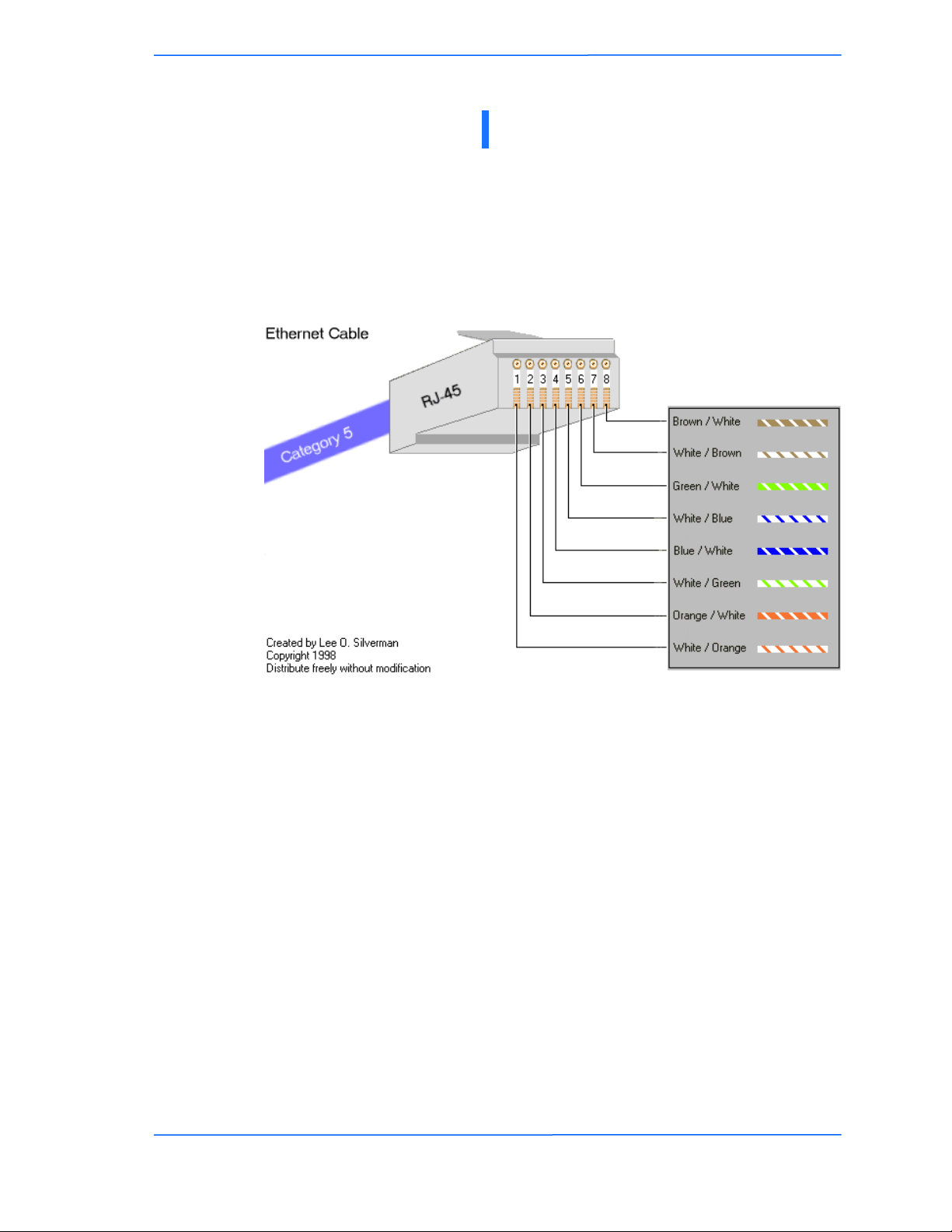
Tranzeo Wireless Technologies
TIA/EIA-568-B is a set of standards for cabling telecommunications products and
services. Follow these standards, as described in the diagram below, to wire the
Cat 5 cable during installation of the Tranzeo radio (see Step 3 in Chapter 2:
Hardware Installation - Installing the Ethernet Cable).
Appendix F
Appendix F: Wiring Standard
TR-5A Series
Pitt Meadows, B.C. Canada V3Y 2V4
111
This document is intended for Public Distribution
19473 Fraser Way,
F-1
Page 66

Tranzeo Wireless Technologies
Appendix G
Appendix G: Routing Quick Start Guide
What do you mean by a routable subnet?
To many people, routing can be a black art. So many explanations of routing explain the binary logic
behind it, but not how to actually use it. This document is designed to offer some practical advise on routing
based on some of the common questions our customers ask us. It is not intended to be the definitive source
of all routing info. For a detailed description, just do an Internet search for routing.
So how does this IP thing work?
Many customers are familiar with a peer-to-peer network, and have never had to deal with connecting two
networks together. In a simple Peer-to-Peer network, every machine talks to every other machine. This
works well when there are 10 machines on the network, but just imagine if there were one million machines
on the network. The answer is to split the millions of units into manageable pieces, or subnets.
Whenever you set up a new machine on an IP network, the minimum IP requirements contain three things,
the address of the machine, the subnet mask for the machine, and the default gateway. Let‘s imagine that
you just moved to a new neighborhood. You need to know three major things to get around, the address of
your house, the street you live on, and since you haven‘t got your internet access set up yet, where the
mailbox is to send your change of address cards. In simple English, the IP info is the house number of the
machine, the sub net mask says what street its on and the default gateway is where the mailbox is located.
On a network, the mailbox is a router.
So how Do I figure out the Subnet Mask?
Figure out how many IP‘s you want to give each location. Find in the maximum IP column the value closest
to, but greater than the number of IP‘s you want to give out. That is the column you should use for your
network
Maximum Number
of IP’s per Subnet
6
14
30
62
126
254
Maximum Number of
Subnets
32
16
8
4
2
1
Sub Net Mask to Use
255.255.255.248
255.255.255.240
255.255.255.224
255.255.255.192
255.255.255.128
255.255.255.0
Total IP’s Available
192
224
240
248
252
254
So what is a gateway?
On an IP network, machines can only send data to here or to there. Here is the IP‘s that are within the
subnet. If the data isn‘t from here, how does it get to there? The answer is that the device sends it to the
Gateway.
The subnet mask tells the machine who is nearby, and who is not. That‘s all it knows. So for example, lets
take a machine with an IP address of 10.10.1.1 on a subnet mask of 255.255.255.0 and a Gateway of
10.10.1.254. The machine has some information for a machine at the address of 10.1.2.1. The subnet mask
of 255.255.255.0 tells the computer that everything that that has an address starting with 10.10.1 is in the
same network. There is a complicated formula to figure out what the subnet mask means, but above is a
table of values for some common situations. Since 10.1.2 does not equal 10.10.1, the data is sent to the
Gateway, which is also called a Router.
TR-5A Series
Pitt Meadows, B.C. Canada V3Y 2V4
111
This document is intended for Public Distribution
19473 Fraser Way,
G-1
Page 67

Tranzeo Wireless Technologies
Appendix G
So what is a Router?
Note: The following is a super simple explanation of a router.
Routers are like a bad boss, they either shout out information to anyone within earshot or they if don‘t know
what to do with the information, they pass the information on to someone else to deal with. This is
commonly referred to as shouting or routing. Routers shout at the machines inside the network, and route
the data addressed to machines located outside their network.
Routers also are like bad bosses in that they have two faces, a public face, and a private face. In network
terms, this means that they have two IP addresses, one a private network, (referred to as the LAN Side) and
one on a public network (referred to as the WAN side). Any traffic it receives that is addressed for an IP
within the Local Range of the subnet, its shouts out ―This is for one of you idiots.‖ Any traffic it receives
that is for an IP that is outside of the range, it politely passes to its Gateway, saying ―Would you mind
sending this for me?‖
To make routing work, the WAN IP needs to be on a different subnet than the LAN one. Just like any other
device using IP, when it has a Packet on the public side, it decides if the packet is for here or there.
TR-5A Series
Pitt Meadows, B.C. Canada V3Y 2V4
222
This document is intended for Public Distribution
19473 Fraser Way,
G-2
Page 68
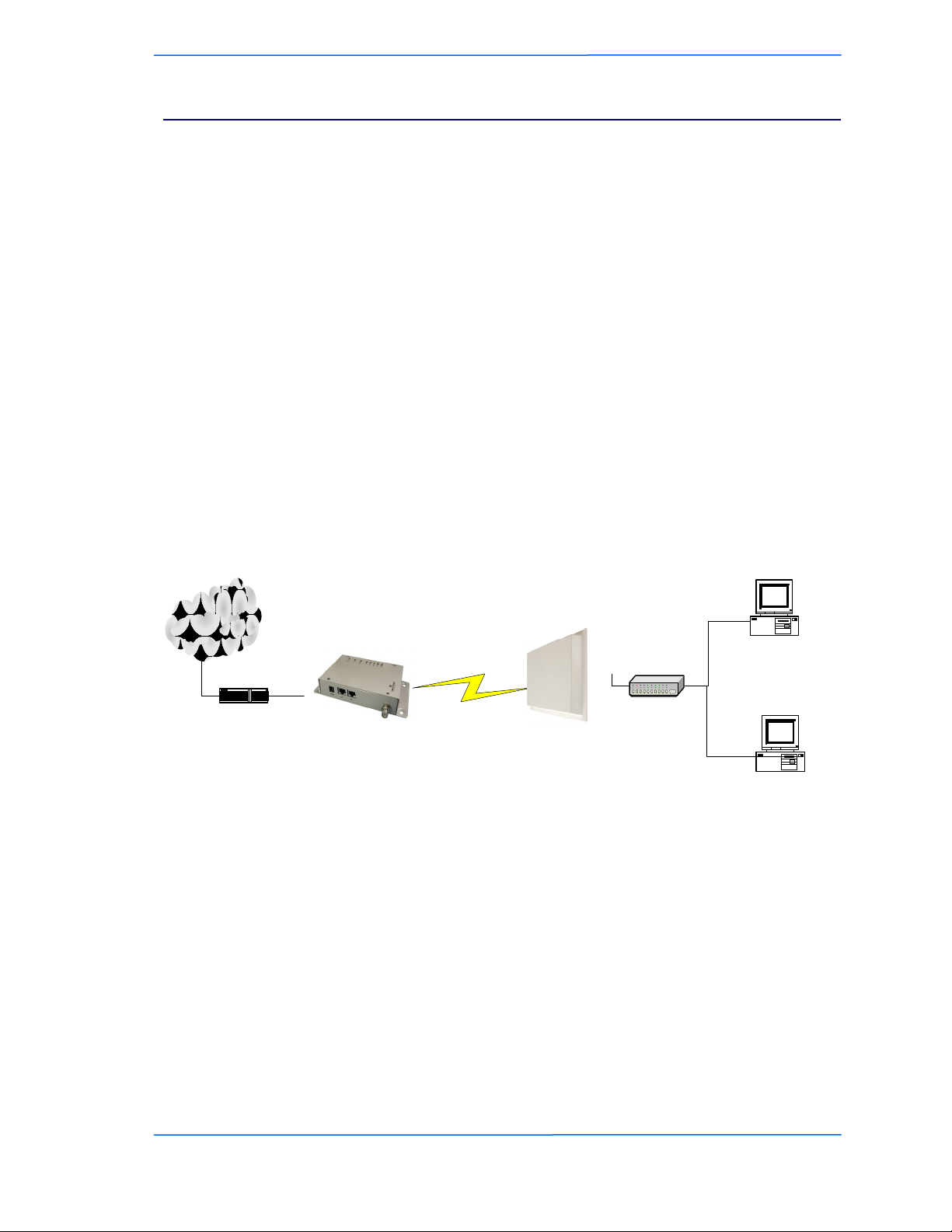
Tranzeo Wireless Technologies
Internet
IP 192.168.1.3/24
Gateway 192.168.1.1
IP 192.168.1.2/24
Gateway 192.168.1.1
T1 Line
Router LAN IP Address
216.129.68.254/24
Switch
Standard NATing Setup
SAI / Router
NAT Turmed On
Wan IP
216.129.68.140 /24
Gateway 216.129.68.254
Lan IP
192.168.1.1/24
AP /Bridge
IP 216.129.68.122/24
Appendix G
Examples
Connecting Multiple Clients to the Internet using NAT
Assuming that you have a full Class C sub net (216.129.68.X), you have 254 possible IP‘s to use, from 1 to
254. The Subnet mask for this can be written as 255.255.255.0 or /24. In order to connect clients to the
Internet, you can make use of Private IP and NAT.
Let‘s keep it simple for now, and use some default values. The Tranzeo Radio uses the default IP address
of 192.168.1.1, and a sub net mask of 255.255.255.0 (or /24) and issues IP addresses using DHCP on that
subnet.
Now our network looks like this:
One subnet that consists of IP‘s ranging from 192.168.1.1 to 192.168.1.254. Using the shout / route rule,
any IP in the 192.168.1.x group shouts to any other IP in that group, but needs to route to any other IP
outside that range. The Gateway, by convention in this document, in placed at the bottom of the range.
By placing client PCs in this one subnet, and the WAN side of the Radio on the public subnet, we can offer
multiple private IPs that will be able to access the Internet. So lets look at an example
TR-5A Series
Pitt Meadows, B.C. Canada V3Y 2V4
333
This document is intended for Public Distribution
19473 Fraser Way,
G-3
Page 69
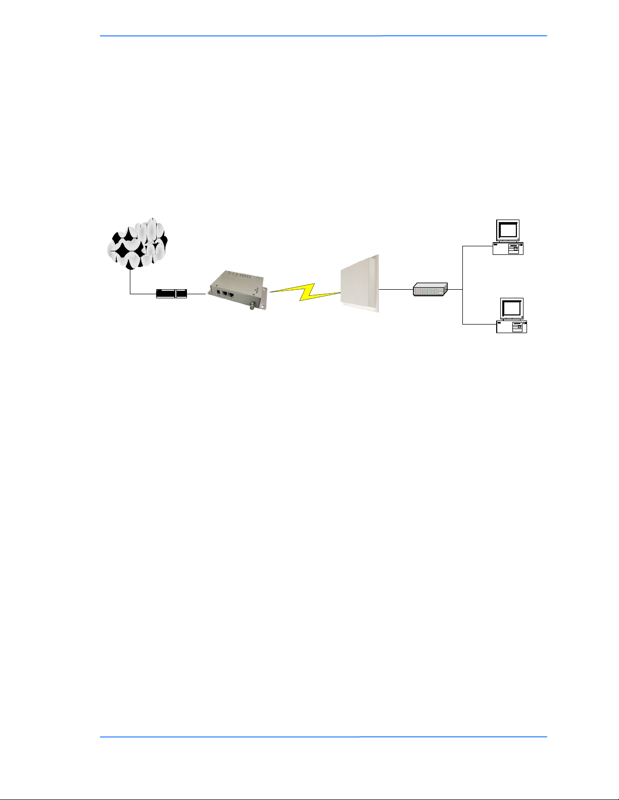
Tranzeo Wireless Technologies
Internet
Lan
216.129.68.1/24
216.129.68.142/24
GW: 216.129.68.1
Switch
Standard Public IP Setup,
Bridging less than 10 PCs
216.129.68.141/24
GW: 216.129.68.1
SAI /Bridge
216.129.68.139 /24
AP /Bridge
IP 216.129.68.122
Appendix G
Public IP’s to less than 10 Clients Through One Radio
Assuming that you have a full Class C sub net, 216.129.68.X, you have 254 possible IP‘s to use, from 1 to
254. The Subnet mask for this can be written as 255.255.255.0 or /24. However, you want to give each
client a public IP. If the client has only PC or a router to attach, then bridge mode will work fine. See
example below. Bridge mode is just like using a switch, the data is not touched as it passes through the
radio. However, bridge mode only bridges up ten devices, if you need to provide public IPs to more than 10
devices on the same radio, you will need to use the router mode.
Lets look at an example
TR-5A Series
Pitt Meadows, B.C. Canada V3Y 2V4
444
This document is intended for Public Distribution
19473 Fraser Way,
G-4
Page 70
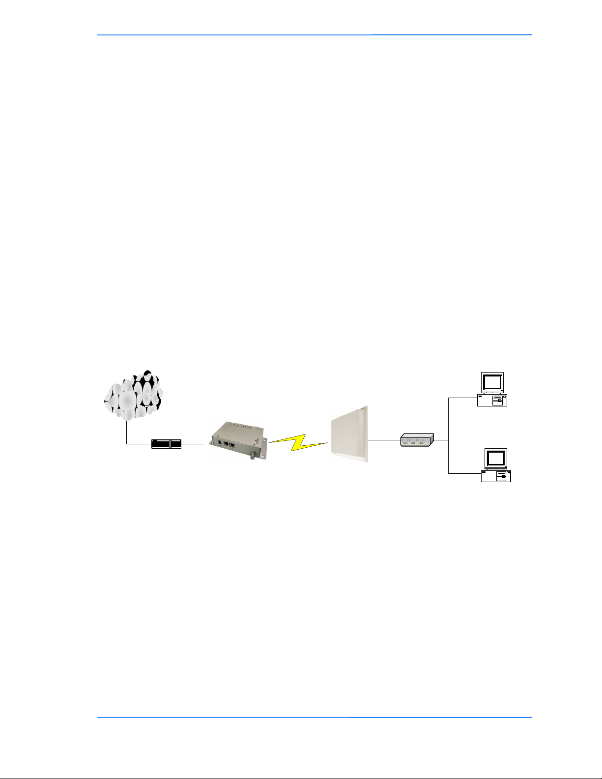
Tranzeo Wireless Technologies
Internet
Lan
216.129.68.1/24
216.129.68.142/30
GW: 216.129.68.140
Switch
Standard Public IP Setup,
Multiple PCs using Router Mode
216.129.68.141/30
GW: 216.129.68.140
SAI /Router
NAT Off
Wan 216.129.68.139 /30
Lan
216.129.68.140/30
AP /Bridge
IP 216.129.68.122
Appendix G
Public IP’s to multiple Clients Through One Radio
Assuming that you have a full Class C sub net, 216.129.68.X, you have 254 possible IP‘s to use, from 1 to
254. The Subnet mask for this can be written as 255.255.255.0 or /24. However, you want to give each
client a public IP. If the client has less than 10 PC‘s or an external router to attach, then bridge mode will
work fine. See example above. But, if they need to have more than 10 computers on a public IP, you need
to subnet your class C license.
Let‘s keep it simple for now, and divide your class C into 2 blocks of 126 licenses each. You‘ll note that ½
of a full class C is not 128 licenses. Every time you divide a subnet, you need to dedicate more IP‘s for use
as broadcasts. To divide into two blocks, we use 255.255.255.128 as our subnet mask. 255.255.255.128 can
also be written as /25.
Now our network looks something like this
One subnet consists IP 216.129.68.1 to 219.129.68.127 and the other consists of 216.129.68.129 to
216.129.68.254. Using the shout / route rule, then any IP in the first group shouts to any other IP in that
group, but need to route to any other IP on the network. The Gateway, by convention in this document, in
placed at the bottom of the range.
By placing client PCs in one subnet, and the WAN side of the Radio on the other subnet, we can offer
multiple public IPs that will route. Unlike in the NATing example, we don‘t need the Router to translate
public to private IP, so make sure that NAT is disabled.
So lets look at an example
TR-5A Series
Pitt Meadows, B.C. Canada V3Y 2V4
555
This document is intended for Public Distribution
19473 Fraser Way,
G-5
Page 71
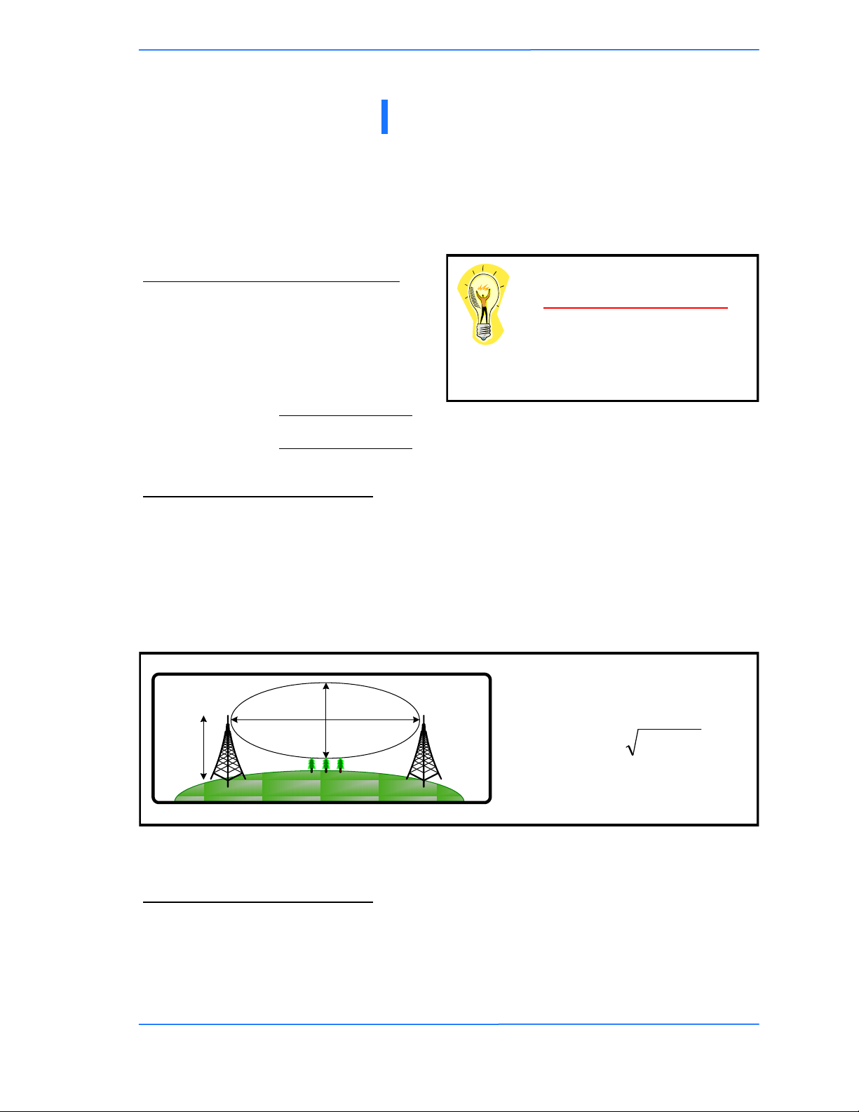
Tranzeo Wireless Technologies
)4/(3.43 fdr
Antenn
a
Height
r = radius
d =
distance
Appendix H
Appendix H: PxP Install Checklist
The following are some of the steps you should go through when
planning a Point to Point (PxP) link.
Step 1: Finding the Location
Determine the 2 endpoint locations.
Calculate the distance between the
locations.
Find the heights of the locations
Link Distance
Tower Heights
Free Space Loss
Free space attenuation = 36.6 + 20log F + 20log D
where F = frequency in MHz and D = distance in
miles
Step 2: Check the Line of
Make sure that the line of sight is clear of obstruction.
Check your Fresnel clearance with calculations to verify that you have enough room in
the center of the path.
Take photos of the line of sight from both sides of the proposed link.
See example 1 below.
Fresnel zone
The cross section radius of the Fresnel zone
is the highest in the center of the RF LoS
which can be calculated as:
where r = radius in feet,
d = distance in miles,
and f = frequency in GHz.
Example 1: Fresnel Zone Calculation
Step 3: Choose Hardware
Select the hardware appropriate for the distance and type of link that you are installing
TR-5A Series
Pitt Meadows, B.C. Canada V3Y 2V4
111
This document is intended for Public Distribution
19473 Fraser Way,
H-1
Page 72

Tranzeo Wireless Technologies
Appendix I: Glossary of Terms
AP: Access Point
ARP: Address Resolution Protocol
CPE: Client Premise Equipment
CTS: Clear To Send
DFS: Dynamic Frequency Selection
DHCP: Dynamic Host Configuration Protocol
DNS: Domain Name Server
DTIM: Delivery Traffic Indication Message
EIRP: Effective Isotropic Radiated Power
FTP: File Transport Protocol
HTML: HyperText Markup Language
HTTP: HyperText Transport Protocol
IP: Internet Protocol
ISP: Internet Service Provider
LAN: Local Area Network
MTU: Maximum Transmission Unit
NAT: Network Address Translation
NIC: Network Interface Card
NOC: Network Operation Center
POP: Post Office Protocol or Point Of Presence
PxP: Point to Point
P2P: Peer to Peer
PPPoE: Point-to-Point Protocol over Ethernet
QOS: Quality Of Service
RADIUS: Remote Authentication Dial-in User Service
RF: Radio Frequency
RTS: Request To Send
SMTP: Simple Mail Transport Protocol
SNMP: Simple Network Management Protocol
TCP: Transmission Control Protocol
TPC: Transmit Power Control
UDP: User Datagram Protocol
VPN: Virtual Private Network
WAN: Wide Area Network
WEP: Wired Equivalent Privacy
WDS: Wireless Distribution System
WINS: Windows Internet Naming Service
WISP: Wireless Internet Service Provider
WPA: Wi-Fi Protected Access
Appendix I
TR-5A Series
Pitt Meadows, B.C. Canada V3Y 2V4
111
This document is intended for Public Distribution
19473 Fraser Way,
I-1
Page 73

Tranzeo Wireless Technologies
Appendix J
Appendix J: AutoConfig
Autoconfig is a feature that allows you to apply configuration settings from a text
file using a TFTP server or by using the radio's web server. The TFTP server
address can be specified as a DHCP parameter using the "next server"
parameter, or specified in the CPE's Configuration Settings page in the HTTP
interface.
The expected configuration filename is in the format <mac address of device>.cfg.
The TFTP and DHCP server must be accessible from the wired side of the CPE.
Any incorrect values or fields in the configuration file will be ignored.
Operation Notes:
1. Configuration settings can be manually imported and exported from the
"Configuration Settings" page in the HTTP interface.
2. AutoConfig is implemented for the following products: TR6xxx, TR-5a, TR-
5plus, TR-5AMP, TR-9xx, TR-FDD, TR-FDD-GT, TR-CPQ, TR-SL2, TR-
SL5, TR-SL9, TR-Multi, and TR-49.
3. A DHCP server is not necessary for AutoConfig. A DHCP server is only
required when the IP mode is set to DHCP client mode. If "next server"
parameter is not specified in the DHCP offer, the TFTP server IP configured
in the HTTP interface will be used as TFTP server address.
4. The units LEDs operate differently when in this mode.
5. To remotely enable the TFTP option, a SNMP set command can be used to
reboot and/or change AutoConfig behavior. The SNMP write string is the
user password.
New features have been added as follow:
1. Downloading configuration file in text format from the HTTP interface is
supported.
2. Uploading configuration file from the HTTP interface is supported.
3. Using a URL to reboot/reset/fallback device is supported.
Examples:
Reboot: http://192.168.1.100/set_config.cgi?admin.cmd=reboot
Reset: http://192.168.1.100/set_config.cgi?admin.cmd=defaults
Store: http://192.168.1.100/set_config.cgi?admin.cmd=store
4. Using URLs to configure device is now supported. The parameters format is
specified as same as ones in autoconfig.txt file.
Examples:
Changing channel and channel bandwidth, then store and reboot:
http://192.168.1.100/set_config.cgi?wireless.channel=6&wireless.channel_b
andwidth=Quarter&admin.cmd=store
TR-5A Series
Pitt Meadows, B.C. Canada V3Y 2V4
111
This document is intended for Public Distribution
19473 Fraser Way,
J-1
Page 74

Tranzeo Wireless Technologies
Appendix J
Example usage:
1. Configure typical CPE parameters for your network in an operational CPE .
2. Save the configuration and store it as a generic name.
3. Open the same configuration, and edit the parameters that will be different
such as
a. IP address
b. Name
c. Passwords
4. Save the edited file as <MAC_of_unconfigured_CPE>.cfg.
You can then load this configuration file in one of two ways:
1) Import it using the Configuration Settings screen
2) Use a TFTP server
Importing the modified text from the HTTP interface of a defaulted CPE is
the easiest method for a single radio:
a) Login to radio
b) Change login password
c) Import configuration file
Applying the configuration file from a TFTP server (Static IP Client):
a) Login to radio
b) Change login password
c) On Configuration Settings page:
i. Check “Enable TFTP Auto-Config”
ii. Specify IP address of TFTP server
iii. Specify filename of configuration file. The file must be in the correct
location for the TFTP server. Consult the TFTP server’s
documentation for information about how to configure the TFTP
server.
iv. Click “Apply & Reboot”
Applying the configuration file from a TFTP server (DHCP IP client):
a) Setup a DHCP server on the same network segment as the wired side of
radio
b) Login to radio
c) Change login password
d) On network Configuration page, change IP mode to DHCP client and apply
e) On Configuration Settings page:
i. Check “Enable TFTP Auto-Config”
TR-5A Series
Pitt Meadows, B.C. Canada V3Y 2V4
222
This document is intended for Public Distribution
19473 Fraser Way,
J-2
Page 75

Tranzeo Wireless Technologies
ii. Specify IP address of TFTP server (Optional if DHCP server
specifies TFTP server in “next server”. Consult your DHCP Server’s
documentation for more information about how to set this option)
iii. Specify filename of configuration file. The file must be in the correct
location for the TFTP server. Consult the TFTP server’s
documentation for information about how to configure the TFTP
server.
iv. Click “Apply & Reboot”
Step 1: Start auto configuration
The unit boots up in auto configuration mode when the auto configuration flag
in flash memory is set. The flag is set as default OFF, and can be set to on via
either the HTTP interface or via an SNMP Set. In auto configuration mode, the
LEDs on the unit are arranged to work in a different way. The power LED is
always blinking to indicate the unit is in the special mode.
Step 2: Link Ethernet
The Ethernet ports are initialized with the radio’s MAC address. The Ethernet
LED shows if the units is linked or not. The radio is always turned off in auto
configuration mode.
Step 3: Obtain IP address
After the Ethernet connection is established, the DHCP request will be sent
out continually until obtaining an IP address. The signal1 LED will blink to
indicate that the DHCP request is being sent out. When a DHCP offer is
received, the signal1 LED turns solid.
Step 4: Connect TFTP server
The unit connects TFTP server using the IP address set in the configuration.
The signal2 LED will blink to indicate that it is trying to establish a connection
with the TFTP server. When it is connected, the LED turns solid and the unit
starts to download the configuration file (named as <MAC_ADDRESS>.cfg)
from the server.
Step 5: Download and parse configuration file
The signal3 LED blinks to indicate that it is downloading and parsing the
configuration file from the TFTP server. The file must be in the correct format
(see the attached sample file). There is only a basic validation for parsing the
file. The incorrect values or fields in the file will be ignored.
Step 6: Store and reboot
The values in the configuration file will be stored into the unit. Signal LED 3-5
turns on for a second, and the unit starts to reboot into the regular mode.
Appendix J
TR-5A Series
Pitt Meadows, B.C. Canada V3Y 2V4
333
This document is intended for Public Distribution
19473 Fraser Way,
J-3
Page 76
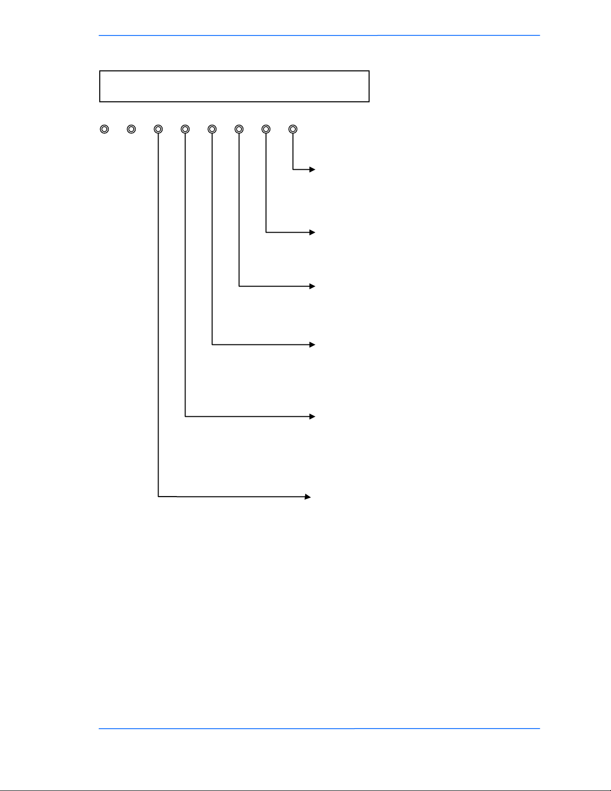
Tranzeo Wireless Technologies
LEDs Arrange for Auto Configuration via TFTP
D13 D14 D15 D20 D19 D18 D17 D16
Appendix J
Ethernet LED:
Off: Ethernet link not established
On: Ethernet link established
Radio LED:
Off: no radio card on the board
On: a radio card on the board
Power LED:
Always blink in auto configuration mode
Signal1 LED:
Off: IP link not established
Blink: sending DHCP request
On: IP link established
Signal2 LED:
Off: TFTP connection not established
Blink: connecting TFTP server
On: TFTP connection established
Signal3 LED:
Off: no file is downloading
Blink: downloading and parsing a file
On: storing and rebooting the unit
TR-5A Series
Pitt Meadows, B.C. Canada V3Y 2V4
444
This document is intended for Public Distribution
19473 Fraser Way,
J-4
Page 77

Tranzeo Wireless Technologies
# **************************
# Auto Configuration for TR6
# Version: 1.0.1
# Date: July 9, 2007
# Version: 1.0.2
# Date: January 29, 2009
# Version: 1.0.3
# Date: October 20, 2009
# Author: Patrick Ping Xu
# **************************
# ----------------------------------------------------------------------------------# Format Instruction:
# (There is no complete validation for the configuration in the firmware.
# The value in an invalid format might be ignored or causing an unexpected value.)
# [STRING.maxlen] a string with maximum length
# [IP] ip address or mask
# [MAC] mac address of 12 hex characters
# [INT.min-max] integer in range from min to max
# [TOKEN] a string of userid:password
# the maximum length of userid and password is 15
# [key1 | key2] a string in the key list
# [RATE] an integer value as below
# 0: Best
# 2: 1M
# 4: 2M
# 11: 5.5M
# 22: 11M
# 12: 6M
# 18: 9M
# 24: 12M
# 36: 18M
# 48: 24M
# 72: 36M
# 96: 48M
# 108: 54M
# [RATES] a string of 4 hex characters
# bit 0: 1M
# bit 1: 2M
# bit 2: 5.5M
# bit 3: 11M
# bit 4: 6M
# bit 5: 9M
# bit 6: 12M
# bit 7: 18M
# bit 8: 24M
# bit 9: 36M
# bit10: 48M
# bit11: 54M
# [STATS] a string of 2 hex characters
# bit 0: LMAC TX/RX
# bit 1: LMAC Interrupt
# bit 2: LMAC Media
# bit 3: Ethernet
# [WEP_KEY] a string of 10 or 26 hex characters
# -----------------------------------------------------------------------------------
Appendix J
TR-5A Series
Pitt Meadows, B.C. Canada V3Y 2V4
555
This document is intended for Public Distribution
19473 Fraser Way,
J-5
Page 78

Tranzeo Wireless Technologies
Appendix J
# -------------------# admin.
# -------------------admin.device_name = TR6Rt # [STRING.19]
admin.admin_token = admin:default # [TOKEN]
admin.super_token = recover:recover # [TOKEN]
admin.led_enabled = Yes # [Yes | No]
admin.snmp_read_community = public # [STRING.14]
admin.snmp_sys_location = Location # [STRING.29]
admin.snmp_sys_contact = Contact # [STRING.29]
admin.snmp_traffic_format = Counter32 # [Counter32 | Integer64 | Counter64]
admin.block_locator_access = No # [Yes | No]
admin.auto_config_enabled = No # [Yes | No] (not used)
admin.auto_config_timeout = 60 # [INT.5-255] unit:second
admin.auto_config_server = 192.168.1.170 # [IP]
admin.auto_config_filename = "" # [STRING.32] (blank when using
{MAC_ADDRESS}.cfg as default)
# -------------------# net.
# -------------------net.network_mode = Bridge # [Bridge | Router]
net.ip_mode = DHCP # [Static | DHCP |
PPPoE]
net.ip_address = 192.168.1.100 # [IP]
net.subnet_mask = 255.255.255.0 # [IP]
net.gateway = 192.168.1.1 # [IP]
net.dns1 = 0.0.0.0 # [IP]
net.dns2 = 0.0.0.0 # [IP]
net.domain_name = "" # [STRING.59]
net.mac_clone_enabled = No # [Yes | No]
net.mac_clone_address = 000000000000 # [MAC]
net.eth1_mode = Auto # [Auto | 10Auto | 10Full |
10Half | 100Auto | 100Full | 100Half]
net.eth2_mode = Auto # [Auto | 10Auto | 10Full |
10Half | 100Auto | 100Full | 100Half]
net.reassociate_on_dhcp = No # [Yes | No]
net.vlan_enabled = No # [Yes | No]
net.vlan_id = 0 # [INT.0-4095]
net.reverse_dhcp_block = No # [Yes | No]
net.shaping_rate = 0 # [INT.0-65535] unit:Kbps
net.shaping_policy = mgmt,icmp # [bypass,mgmt,icmp,mcast] (bitmap)
# -------------------# net.router.
# -------------------net.router.lan_ip_address = 192.168.100.1 # [IP]
net.router.lan_subnet_mask = 255.255.255.0 # [IP]
net.router.allow_ping = Yes # [Yes | No]
net.router.allow_web = Yes # [Yes | No]
net.router.web_port = 80 # [INT.1-65535]
net.router.web_timeout = 60 # [INT.0-65535]
net.router.mtu_use_default = Yes # [Yes | No]
net.router.mtu = 1500 # [INT.500-3000]
TR-5A Series
Pitt Meadows, B.C. Canada V3Y 2V4
666
This document is intended for Public Distribution
19473 Fraser Way,
J-6
Page 79

Tranzeo Wireless Technologies
net.router.nat_enabled = Yes # [Yes | No]
# -------------------# net.router.route.
# -------------------net.router.route.user_gateway_enabled = No # [Yes | No]
net.router.route.user_gateway_interface = WAN # [WAN | LAN]
net.router.route.user_gateway = 0.0.0.0 # [IP]
; entries 0-7
net.router.route.interface.0 = None # [WAN | LAN | None]
net.router.route.ip_address.0 = 0.0.0.0 # [IP]
net.router.route.subnet_mask.0 = 0.0.0.0 # [IP]
net.router.route.gateway.0 = 0.0.0.0 # [IP]
net.router.route.metric.0 = 0 # [INT.0-255]
# -------------------# net.router.ip_filter.
# -------------------; it must be enabled before entry fields
net.router.ip_filter.enabled = No # [Yes | No]
; entries 0-31
net.router.ip_filter.access.0 = Allow # [Allow | Deny]
net.router.ip_filter.interface.0 = WAN # [WAN | LAN]
net.router.ip_filter.protocol.0 = TCP # [TCP | UDP | ICMP]
net.router.ip_filter.icmp_type.0 = 0 # [INT.0-255]
net.router.ip_filter.source_ip_start.0 = 0.0.0.0 # [IP]
net.router.ip_filter.source_ip_end.0 = 0.0.0.0 # [IP]
net.router.ip_filter.source_port_start.0 = 0 # [0-65535]
net.router.ip_filter.source_port_end.0 = 0 # [0-65535]
net.router.ip_filter.destination_ip_start.0=0.0.0.0 # [IP]
net.router.ip_filter.destination_ip_end.0 = 0.0.0.0 # [IP]
net.router.ip_filter.destination_port_start.0 = 0 # [0-65535]
net.router.ip_filter.destination_port_end.0 = 0 # [0-65535]
# -------------------# net.router.port_forward.
# -------------------; it must be enabled before entry fields
net.router.port_forward.enabled = No # [Yes | No]
; entries 0-31
net.router.port_forward.actived.0 = No # [Yes | No]
net.router.port_forward.protocol.0 = TCP # [TCP | UDP]
net.router.port_forward.external_port.0 = 0 # [0-65535]
net.router.port_forward.internal_address.0=0.0.0.0 # [IP]
net.router.port_forward.internal_port.0 = 0 # [0-65535]
# -------------------# net.router.dhcp_server.
# -------------------net.router.dhcp_server.enabled = Yes # [Yes | No]
net.router.dhcp_server.range_start=192.168.100.100 # [IP]
net.router.dhcp_server.range_length = 100 # [INT.0-255]
net.router.dhcp_server.lease_time = 1440 # [INT.0-65535] unit:minute
net.router.dhcp_server.gateway_use_default = Yes # [Yes | No]
net.router.dhcp_server.gateway = 192.168.100.1 # [IP]
net.router.dhcp_server.dns_use_wan_assigned = No # [Yes | No]
Appendix J
TR-5A Series
Pitt Meadows, B.C. Canada V3Y 2V4
777
This document is intended for Public Distribution
19473 Fraser Way,
J-7
Page 80

Tranzeo Wireless Technologies
net.router.dhcp_server.dns1 = 0.0.0.0 # [IP]
net.router.dhcp_server.dns2 = 0.0.0.0 # [IP]
net.router.dhcp_server.dns_relay_enabled = Yes # [Yes | No]
net.router.dhcp_server.domain_use_wan_assigned = No # [Yes | No]
net.router.dhcp_server.domain_name = localdomain # [STRING.59]
net.router.dhcp_server.wins_use_wan_assigned = No # [Yes | No]
net.router.dhcp_server.wins1 = 0.0.0.0 # [IP]
net.router.dhcp_server.wins2 = 0.0.0.0 # [IP]
# -------------------# net.router.qos.
# -------------------net.router.qos.enabled = No # [Yes | No]
net.router.qos.uplink_speed = 4096 # [INT.0-65535] unit:Kbps
net.router.qos.auto_classify = Yes # [Yes | No]
net.router.qos.dynamic_fragmentation = Yes # [Yes | No]
; entries 0-7
net.router.qos.actived.0 = No # [Yes | No]
net.router.qos.priority.0 = 0 # [INT.0-255]
net.router.qos.name.0 = "" # [STRING.15]
net.router.qos.protocol.0 = 0 # [INT.0-255]
net.router.qos.source_ip_start.0 = 0.0.0.0 # [IP]
net.router.qos.source_ip_end.0 = 0.0.0.0 # [IP]
net.router.qos.source_port_start.0 = 0 # [0-65535]
net.router.qos.source_port_end.0 = 0 # [0-65535]
net.router.qos.destination_ip_start.0 = 0.0.0.0 # [IP]
net.router.qos.destination_ip_end.0 = 0.0.0.0 # [IP]
net.router.qos.destination_port_start.0 = 0 # [0-65535]
net.router.qos.destination_port_end.0 = 0 # [0-65535]
# -------------------# net.router.pppoe.
# -------------------net.router.pppoe.service_name = "" # [STRING.15]
net.router.pppoe.username = "" # [STRING.40]
net.router.pppoe.password = "" # [STRING.15]
net.router.pppoe.ip_address = 0.0.0.0 # [IP]
net.router.pppoe.subnet_mask = 0.0.0.0 # [IP]
net.router.pppoe.gateway = 0.0.0.0 # [IP]
net.router.pppoe.dns1 = 0.0.0.0 # [IP]
net.router.pppoe.dns2 = 0.0.0.0 # [IP]
net.router.pppoe.max_idle_time = 0 # [INT.0-65535] unit:minute
net.router.pppoe.reconnect_mode = Demand # [Always | Demand | Manual]
net.router.pppoe.user_settings_enabled = No # [Yes | No]
# -------------------# wireless.
# -------------------wireless.mode = CPE # [AP | CPE]
wireless.ssid = default # [STRING.32]
wireless.secondary_ssid = "" # [STRING.32]
wireless.channel = 50 # [INT.0-255]
wireless.channel_bandwidth = Full # [Full | Half | Quarter]
wireless.gmode_enabled = No # [Yes | No]
wireless.indoor_mode = Yes # [Yes | No]
wireless.turbo = No # [Yes | No]
Appendix J
TR-5A Series
Pitt Meadows, B.C. Canada V3Y 2V4
888
This document is intended for Public Distribution
19473 Fraser Way,
J-8
Page 81

Tranzeo Wireless Technologies
Appendix J
wireless.country_code = US # [STRING.3]
wireless.tx_rate = 0 # [RATE]
wireless.tx_supported_rates = 0003 # [RATES]
wireless.rts_threshold = 3000 # [INT.0-3000]
wireless.beacon_period = 100 # [INT.0-65535] unit:ms
wireless.burst_time = 0 # [INT.0-65535]
wireless.fragmentation_threshold = 2346 # [INT.256-2346]
wireless.dot11d_enabled = No # [Yes | No]
wireless.dot11h_mode = None # [None | User | Auto]
wireless.invisibility = No # [Yes | No]
wireless.dtim_interval = 1 # [INT.0-255]
wireless.wds_enabled = No # [Yes | No]
wireless.wds_mac_address.0 = 000000000000 # [MAC]
wireless.wds_mac_address.1 = 000000000000 # [MAC]
wireless.wds_mac_address.2 = 000000000000 # [MAC]
wireless.wds_mac_address.3 = 000000000000 # [MAC]
wireless.wds_mac_address.4 = 000000000000 # [MAC]
wireless.wds_mac_address.5 = 000000000000 # [MAC]
wireless.pxp_enabled = No # [Yes | No]
wireless.pxp_mac_address = 000000000000 # [MAC]
wireless.extended_info_enabled = Yes # [Yes | No]
wireless.block_inter_client_traffic = Yes # [Yes | No]
wireless.power_cap = 60 # [INT.-60-+60] unit:0.5dBm
wireless.antenna_gain = 60 # [INT.0-200] unit:0.5dBi
wireless.ack_timeout = 740 # [INT.0-4195] =distance(km)/0.15
wireless.ack_tuning = 0 # [INT.-100-100] =us
wireless.long_preamble = No # [Yes | No]
wireless.stats_mode = 04 # [STATS]
wireless.wds_stats = 0 # [INT.0-7]
wireless.cpe_stats = 0 # [INT.0-7]
# -------------------# wireless.security.
# -------------------wireless.security.mode = WPA # [None | WEP | WPA | WPA2]
; WEP parameters are used only when the mode is WEP
; all WEP key entries (0-3) must have same length
wireless.security.wep_authentication = Open # [Open | Shared]
wireless.security.wep_key_index = 0 # [INT.0-3]
wireless.security.wep_key.0 = 1234567890 # [WEP_KEY]
wireless.security.wep_key.1 = 1234567890 # [WEP_KEY]
wireless.security.wep_key.2 = 1234567890 # [WEP_KEY]
wireless.security.wep_key.3 = 1234567890 # [WEP_KEY]
; WPA parameters are used only when the mode is WPA or WPA2
; For WPA, the cipher can only be either TKIP or AES
; For WPA2, the cipher can only be either AES(WPA2 only) or TKIP_AES(WPA2)
; the cipher must be defined after wireless.security.mode
wireless.security.wpa_cipher = TKIP # [TKIP | AES | TKIP_AES]
; the wpa_compatible must be defined after wireless.security.wpa_cipher
wireless.security.wpa_compatible = No # [Yes | No]
wireless.security.wpa_psk = password # [STRING.63]
wireless.security.wpa_update_interval = 3600 # [INT.0-65535] unit:second
wireless.security.radius_enabled = No # [Yes | No]
wireless.security.radius_server_address = 0.0.0.0 # [IP]
wireless.security.radius_server_port = 1812 # [INT.0-65535]
wireless.security.radius_timeout = 60 # [INT.0-65535]
TR-5A Series
Pitt Meadows, B.C. Canada V3Y 2V4
999
This document is intended for Public Distribution
19473 Fraser Way,
J-9
Page 82

Tranzeo Wireless Technologies
Appendix J
wireless.security.radius_shared_secret = password # [STRING.64]
wireless.security.radius_auth_mac = Yes # [Yes | No]
# -------------------# wireless.access_control.
# -------------------; it must be enabled before entry fields
wireless.access_control.enabled = No # [Yes | No]
; entries 0-255
wireless.access_control.mac.0 = FFFFFFFFFFFF # [MAC]
wireless.access_control.access.0 = Allow # [Allow | Deny]
# -------------------# duplex.
# (NOTE: only available for FDD)
# -------------------; 0=MASTER, 1=SLAVE
duplex.rx_master = Yes # [Yes | No] (NOTE:
wireless.mode is not available for FDD)
duplex.rx_channel = 165 # [INT.1-255] (NOTE:
wireless.channel is not available for FDD)
duplex.ssid.0 = FDD_MST # [STRING.32] (NOTE:
wireless.ssid is not available for FDD)
duplex.ssid.1 = FDD_SLV # [STRING.32]
duplex.pxp_mac_address.0 = 000000000000 # [MAC] (NOTE:
wireless.pxp_enabled and wireless.pxp_mac_address is not available for FDD)
duplex.pxp_mac_address.1 = 000000000000 # [MAC]
duplex.mac_clone_enabled.0 = No # [Yes | No] (NOTE:
net.mac_clone_enabled is not available for FDD)
duplex.mac_clone_enabled.1 = No # [Yes | No]
duplex.mac_clone_address.0 = 000000000000 # [MAC] (NOTE: net.mac_clone_address is
not available for FDD)
duplex.mac_clone_address.1 = 000000000000 # [MAC]
TR-5A Series
Pitt Meadows, B.C. Canada V3Y 2V4
101010
This document is intended for Public Distribution
19473 Fraser Way,
J-10
Page 83
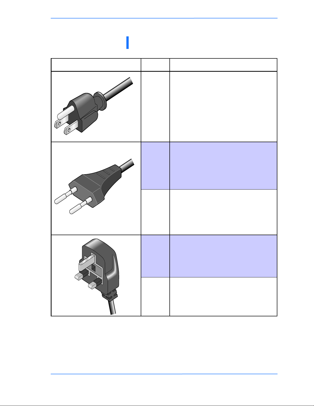
Tranzeo Wireless Technologies
Appendix K: Tranzeo Electrical Plugs
Electrical Plug Type Letter Description
Appendix K
*
FCC / North American
F
adapter
C ETSI / Euro adapter
FCC / Euro adapter A
U ETSI / UK adapter
* 24 volt version shown.
TR-5A Series
Pitt Meadows, B.C. Canada V3Y 2V4
111
This document is intended for Public Distribution
19473 Fraser Way,
FCC / UK adapter M
K-1
Page 84

Tranzeo Wireless Technologies
Appendix L: Warranty Terms
Effective Jan 1st, 2008
Warranty Period Summary for
All Tranzeo Brand WiFi Units
All Warranties now start from Day of Invoice
Accessories Radios
Items
Warranty
Term
All Power
Supplies
and POE
90 Days 1 year 1 year 2 Years 3 Years
All Cables
and
Antennas
Sold Before
May 1st, 06
Sold Before
Dec 1st, 06
Sold Before
Jan 1st, 08
Appendix L
Sold After
Jan 1st, 08
3 Years Parts
and Labor plus
additional 2
years on Parts
Warranty Terms
1. Items Covered By a 3 Year Labor / 5 Year Parts Warranty (Total Coverage 5
Years)
· All Tranzeo Wireless CPE, AP and Backhaul Radio products Sold After Jan
1st, 2008 are warranted against defects in material and workmanship for a
period of three years from date of sale, under normal use, with the exception
of items listed in paragraphs (1) , (2) , (3) and (4).
2. Items Covered By a Three Year Warranty
· All Tranzeo Wireless CPE, AP and Backhaul Radio products Sold
Before Jan 1st, 2008 are warranted against defects in material and
workmanship for a period of three years from date of sale, under normal
use, with the exception of items listed in paragraphs (1) , (2) and (3).
3. Items Covered By a Two Year Warranty
· All other Tranzeo Wireless CPE, AP and Backhaul Radio products sold
before Dec 1st, 2006 are warranted against defects in material and
workmanship for a period of two years from date of sale, under normal
use., with the exception of items listed in paragraph (1) and (2)
TR-5A Series
Pitt Meadows, B.C. Canada V3Y 2V4
111
This document is intended for Public Distribution
19473 Fraser Way,
L-1
Page 85

Tranzeo Wireless Technologies
4. Items Covered By A One Year Warranty
The following Tranzeo Wireless manufactured products are warranted
against defects in material and workmanship for a period of one year from
date of Manufacture, under normal use:
· All products sold prior to May 1st, 2006
· All TR-CPE200 products regardless of Sale Date
· All Antennas
· All Cables
5. Tranzeo Wireless manufactured products are covered by a Parts and Labor Depot
Warranty. Depot warranty means the customer is responsible for delivering the
defective product to the designated service depot for repair or replacement.
Appendix K
6. During the first 3 years of ownership, should a valid warranty claim arise, Tranzeo
will repair or replace the unit at no cost to the user. After the first 3 years,
Tranzeo will further warranty the material and workmanship for an additional 2
years. During the 4th and 5th years of the warranty, there shall be no charge for
parts and the Tranzeo will charge the prevailing shop rate to repair the unit, to a
maximum of 1/2 hour, should a valid warranty claim arise.
7. VAT, Customs and other local taxes are the responsibility of the customer.
8. Tranzeo Wireless will repair or replace a product that was found to be defective by
Tranzeo during the warranty period at its discretion.
9. All non-Tranzeo manufactured products carry the Original Equipment
Manufacturer's warranty, which is passed on by Tranzeo Wireless. Warranty
Claims against non-Tranzeo manufactured products must be filed with the
appropriate manufacturer.
10. This warranty does not cover dealer labor cost for removing and reinstalling the
machine for repair nor for any expendable parts that are readily replaced in
normal use.
TR-5A Series
Pitt Meadows, B.C. Canada V3Y 2V4
222
This document is intended for Public Distribution
19473 Fraser Way,
K-2
Page 86

Tranzeo Wireless Technologies
11. The sole responsibility of Tranzeo Wireless Systems under this warranty shall be
limited to repair of this product, or replacement thereof, at the sole discretion of
Tranzeo Wireless Systems
.Special Warranty Terms For Customers
Appendix K
in Canada, USA and the European Union
12. All RMA items shipped to Tranzeo Wireless must be freight prepaid. Tranzeo
Wireless will pay the return freight via a service of Tranzeo Wireless
Technologies' choice. Customer is responsible for payment of any shipping
upgrades.
Special Warranty Terms For Customers
in All Other Regions
13. All RMA items shipped to Tranzeo Wireless must be freight prepaid. Tranzeo
Wireless will prepay and bill the return freight and taxes (CFR Cost and Freight)
via a service of Tranzeo Wireless Technologies' choice. Customer is responsible
for payment of any
Shipping upgrades
14. Shipping costs must be prepaid
Limitation of Warranty
This warranty does not apply if the Product:
a. has been opened and/or altered, except by Tranzeo Wireless Technical Personnel,
b. has been painted in way shape or form,
c. has been damaged due to errors or defects in cabling
d. has not maintained in accordance with instructions supplied by Tranzeo Wireless,
e. has been subjected to abnormal physical or electrical stress, including lightning strike,
misuse, negligence, or accident;
f. removal of serial number label, or
g. equipment sold under resale agreements, i.e. Amplifiers, Antennas.
TR-5A Series
Pitt Meadows, B.C. Canada V3Y 2V4
333
This document is intended for Public Distribution
19473 Fraser Way,
K-3
Page 87

Tranzeo Wireless Technologies
Appendix K
Who to Contact for an RMA?
There are 3 ways to discuss any technical difficulties and request an RMA #:
1. Fill out our online RMA Request Form at
http://support.tranzeo.com/rmarequest.php
2. Call our Technical Support Center via the local number listed at
http://support.tranzeo.com
What information will be required?
1. Customer name/ID # and contact information
2. Proof of Warranty Status (such as a copy of Invoice showing Serial Number, Mac
Address and Date of Sale)
3. Problem Description
4. Part Number or Serial Number
5. Troubleshooting actions taken so far
Warranty Repair
a. RMA number is valid for 180 days only.
b. If the product is not received within 180 days, the RMA will be cancelled.
c. Tranzeo Wireless will carefully test and evaluate all returned products and will repair or replace
defective products that are under warranty at no charge.
d. If the malfunction is due to a manufacturing defect, it will be repaired, tested, tuned and
calibrated as necessary, with strict adherence to factory specified procedures and parts, to
working order.
e. If the malfunction is due to an issue not covered by warranty, a $35.00 evaluation fee will be
charged, plus the actual costs of the repair. Tranzeo's current shop rate is $70.00 per hour, plus
parts.
f. When your unit is returned to you, you must restore configuration and or applications before full
use can resume.
g. If the product cannot be repaired, a refurbished replacement product will be provided.
h. However, if Tranzeo Wireless cannot duplicate the problem or condition causing the return, the
unit will be returned to the customer at the customers cost as: "No Problem Found" and a $35.00
evaluation fee may be charged.
TR-5A Series
Pitt Meadows, B.C. Canada V3Y 2V4
444
This document is intended for Public Distribution
19473 Fraser Way,
K-4
Page 88
Tranzeo Wireless Technologies
i. Repaired or replaced product will be subject to the original warranty period but not less than 90
days.
j. All items must be shipped pre-paid. Tranzeo Wireless will not accept any collect packages.
Tranzeo will pay the shipping to return your products. We recommend insuring the package using
the values from our commercial invoice.
k. Be sure to package the items well. Original packaging should be used for shipping. Tranzeo is
not responsible for further damage caused to the unit due to inadequate packaging.
l. We recommend that you use a shipping service with tracking (i.e. UPS/FedEx ground) to ship
your RMA. Tranzeo will not accept any packages that arrive with charges owing.
m. Be sure to include the password for each device. Any device that arrives without a password
may be subject to a $60 rebuilding charge per unit.
Appendix K
Depot Locations
Mexico, Caribbean and South America
Australia and APAC countries
Africa, Asia and Middle East
* Note: PacificNet is an authorized Repair Center for its Customers in Mexico
Radio Location
Canada
USA
EU
Depot Location
Canada
USA
Ireland
Canada*
Canada
Ireland
Out of Warranty Replacements
a) Product that is out warranty will be repaired on a fee for service basis at Tranzeo's
shop rate of $75.00 per hour plus parts. A $75.00 deposit is charged for all nonwarranty repairs when the RMA is issued.
b) Any goods left for more than 90 days without instructions will be considered
abandoned and be disposed of.
What to ship?
a) Products that are returned for RMA work should be shipped in the original
package and include the items that that are to be repaired.
b) All returned product must reference the RMA # on the outside of the box.
TR-5A Series
Pitt Meadows, B.C. Canada V3Y 2V4
555
This document is intended for Public Distribution
19473 Fraser Way,
K-5
Page 89

Tranzeo Wireless Technologies
c) A returned product without clearly marked RMA # will be refused and returned to
sender.
How to ship?
a) We recommend that you use a shipping service with tracking (i.e. UPS/FedEx
ground) to ship your RMA.
b) Products returned for warranty repair or out-of-warranty replacement, must be
marked with a valid RMA number and shipped FOB Destination, Prepaid.
c) Approximate turnaround time is 21 business days for warranty repairs and
replacements.
d) Shipping Time is generally 7 business days to any location in the United States.
Appendix K
e) Tranzeo Wireless will refuse any item that does not have an RMA# clearly
marked on the outside of the box.
f) Tranzeo Wireless is NOT responsible for any damage to the products during
transit by the shipping company.
g) All claims for shipment errors must be made within 3 days after receipt of
shipment.
Warranty Disclaimer
Except in only the limited express warranty set forth above, there are no expressed or implied
warranties of merchantability and fitness for a particular purpose. In no event will Tranzeo
Wireless Systems be liable for any direct, special, or consequential damages arising out of, or in
connection with, the delivery, use, inability to use, or performance of this product.
Goods Damaged in Transit
Tranzeo Wireless Technologies ships all items FOB Factory. This means that title for the item
transfers to the buyer once the courier picks up the package. If there is damage, a claim must be
filed with the courier by the owner of the goods, which is the buyer. Shipping damage is not
covered by the warranty.
Damage claims are solely between the recipient of the goods and the
courier.
TR-5A Series
Pitt Meadows, B.C. Canada V3Y 2V4
666
This document is intended for Public Distribution
19473 Fraser Way,
K-6
Page 90

Tranzeo Wireless Technologies
Shipping Firms do have legal obligations and limitations as to when and how much to compensate
for damage, but only if the claim is filed on time and in the correct manner. You must file the claim
as soon as possible.
Appendix K
Making a Damage Claim
If you receive a shipment that appears to have been damaged by the shipper during shipping, take the steps on the on the box then contact us so we have a record of the incident. We will assist in any way we can in filing and advocating for
your claim.
If you choose to accept the shipment and sign for it, have the shipper stay with
you while you open and inspect the contents of the container for any additional
damage that was not visible before opening. Make sure the shipper notes all damage on the shipping bill before you sign. By signing the waybill, you release the
Shipping Company from all obligations unless the damage is clearly noted.
If it is possible to take any photos of the damage and forward to the shipper and
us, Before signing the shipping bill (for receipt of the shipment), have the shipper
note on the shipping bill the exact details of the damage.
If the damage appears to be very extensive, you still should
not refuse the shipment. Refusing the shipment will delay
your claim.
DO NOT sign anything if you choose to refuse the shipment.
TR-5A Series
Pitt Meadows, B.C. Canada V3Y 2V4
777
This document is intended for Public Distribution
19473 Fraser Way,
K-7
Page 91

Tranzeo Wireless Technologies
Appendix M: How Can We Improve?
Appendix M
Please take a moment to help us improve your experience with Tranzeo Wireless. Please fax the
completed questionnaire to 604-460-6005. Each month we will draw for a free gift.
Product Quality
Was this your first order from Tranzeo
Wireless?
Yes
No
How would you rate our website?
Very Informative
Generally good
Quality varies
Poor quality
Was your order complete?
Yes
No, I was missing:
_______________________
How would you rate our packaging?
Consistent high quality
Generally good
Quality varies shipment to shiment
Poor quality
How would you rate our order process?
Consistent high quality
Generally good
Quality varies daily
Poor quality
How would you rate our Technical Support?
Consistent high quality
Generally good
Quality varies each time
Poor quality
Service and Environment
Did you Sales Rep answer all your questions
and explain your best options?
Yes
No
How would you rate the Tranzeo Wireless
staff you have dealt with to date?
Friendly and helpful
Average
Varies on each call
Poor service
How long did you wait for your product
after ordering?
1 to 3 days
3 to 5 days
More than 5 days
Was the entire experience positive?
Yes
No
If No why?:___________________
Additional Comments
_______________________________________________________________________________
_______________________________________________________________________________
About You (optional)
Name
Address
City, State, ZIP Code
May we add you to our mailing list, which offers news and exciting promotions? □ Yes □ No
E-mail
Phone
Thank you for your participation!
TR-5A Series
Pitt Meadows, B.C. Canada V3Y 2V4
111
This document is intended for Public Distribution
19473 Fraser Way,
M-1
Page 92

Tranzeo Wireless Technologies
Appendix N
Appendix N: Notes
TR-5A Series
Pitt Meadows, B.C. Canada V3Y 2V4
111
This document is intended for Public Distribution
19473 Fraser Way,
N-1
 Loading...