


S
S
S
-
-
-
D
D
D
7
7
7
8
8
8
0
0
0
2
2
2
D
D
D
i
i
i
g
g
g
i
i
i
t
t
t
a
a
a
l
l
l
W
W
W
i
i
i
r
r
r
e
e
e
l
l
l
e
e
e
s
s
s
s
s
s
R
R
R
e
e
e
c
c
c
e
e
e
i
i
i
v
v
v
e
e
e
r
r
r
I
I
I
n
n
n
s
s
s
t
t
t
r
r
r
u
u
u
c
c
c
t
t
t
i
i
i
o
o
o
n
n
n
M
M
M
a
a
a
n
n
n
u
u
u
a
a
a
l
l
l

1
Table of Contents
1. Safety Precautions
2. General Description
3. Features
4. Items and Functions
5. Connection Examples
6. Menu Operation
7. Sharing An Antenna Between Two Receivers
8. Sharing An Antenna Among Three Or More
Receivers
9. About The Antenna Mounting Kit
10. Monitoring With Headphones
11. Headphone Cascade Connections
12. About The Network Function
13. Specifications
14. Accessories Included

2
The Trantec SD-7802 Receiver represents our commitment to our customers by
providing high quality, reliable wireless audio links, using our considerable design
expertise gained over many years as a leading edge manufacturer.
Thank you for purchasing this product and please study this manual, especially the safety
instructions before installing and using this equipment.
1. SAFETY PRECAUTIONS
• Keep the system away from direct sources of heat, e.g. Central heating radiators,
heaters, and direct sunlight.
• Do not expose the unit to an environment where it could be splashed with liquids as this
may result in fire or electric shocks.
• Keep the system clean by using a slightly damp cloth. Never use household cleaning
agents or solvents.
• Avoid using or storing the system in damp or dusty conditions.
• Always disconnect from the AC outlet when not in use.
• The unit is designed for indoor use, do not install it outdoors. If the unit should get wet,
there is a danger of electric shock.
• Never remove the external covers of the unit, exposing the electronics, or modify the unit
in any way.
• Do not handle the mains lead with wet hands.
• Never pull the cord of the AC lead when disconnecting from an AC outlet. Always hold
the plug.
• Ensure that the mains plug is securely inserted in the wall outlet.
• Route the AC power lead in such a way that it is not likely to be stepped on or tripped
over.
• Do not use if the AC lead becomes damaged. This may result in fire or electric shock.
• Never touch any part of the equipment during a thunderstorm as this may result in severe
electric shock.
• Use the unit only with the voltage specified on it. Using a voltage higher than that
specified may result in fire or electric shock.
• Do not cut, kink, otherwise damage or modify the power supply cord. In addition, never
place heavy objects (including the unit itself) on the power cord. Doing so may result in
fire or electric shock.
• Always mount the unit on a stable surface or install in a stable location. The unit may
otherwise fall causing personal injury and/or property damage.
• When moving the unit, be sure to remove its power supply cord from the wall outlet first.
Moving the unit with the power cord connected to the outlet may cause damage to the
power cord, resulting in fire or electric shock.
• Do not place heavy objects on the unit as this may cause the unit to fall resulting in
personal injury and/or property damage. In addition, the object itself may fall off and
cause injury and/or damage.
• Do not place containers of liquid or metallic objects on top of the unit. If they accidentally
spill into the unit, this may cause a fire or electric shock.
Should the covers be removed or there is any other breach of the above instructions, the
warranty becomes null and void, in addition to personal risk from burns and/or electric
shock.
If any of the following conditions occur when using the unit, switch off and remove the AC
lead from the outlet immediately and contact your nearest dealer.
• Smoke or unusual smell
• Water or foreign object inside the unit
• Physically damaged housings

3
DO NOT REMOVE COVER.
NO USER SERVICEABLE PARTS INSIDE.
REFER SERVICING TO QUALIFIED SERVICE PERSONNEL.
The lightning flash with arrowhead within a triangle is intended to tell the user that parts
inside the product are a risk of electric shock to persons.
The exclamation point within a triangle is intended to tell the user that important
operating and servicing instructions are in the manual provided with the equipment.
WARNING - Indicates a potentially hazardous situation that could result in death or
serious personal injury.
CAUTION - Indicates a potentially hazardous situation that could result in moderate or
minor personal injury, and/or property damage.

4
2. General Description
The S-D7802 is a dual UHF wireless receiver that employs a digital diversity system and
supports digital audio transmission.
3. Features
• High quality 32kHz/24-bit digital audio data reception
• Digital audio transmission capability eliminates the need for an analog compander, thus
freeing the S-D7802 from compander-induced distortion and dynamic tracking
inaccuracies
• True Diversity receiver ensures stable radio signal reception
• High multi-channel density
• Industry standard digital interface support
• Display of transmitter battery life and setting information from the transmitter
• Can be monitored and remotely controlled by a PC
• LAN audio monitoring facility
• Wide receiver RF Bandwidth, typically 60MHz
4. Items and Functions
[Front Panel]
AF
dB
0
-9
-18
-27
-36
300
100
30
10
A BµV
RF
ANT BATT
A B
E F
RF
A B
1000
300
100
30
10
0
-9
-18
-27
-36
AF
µV dB
ANT
A B
BATT
E F
GROUP CHGROUP CH
UNIT 1 UNIT 2
UNIT 1 UNIT 2
UNIT1 2
VOL
MIN MAX
OUTPUT
BAND
ANT ATT A
ANT ATT B
RF CASCADE
LAN
LAN RESET
DIGITAL WIRELESS TUNER S-D7802
1 2
0 -10 -20
0 -10 -20dBdB
ANT A ANT B
FULL/COL
REMOTE LINK/ACT
SET
PHONES
Radio Signal Reception Level Meter
Bargraph LEDs light to indicate strength of signal received by the corresponding antenna.
Audio Input Level Meter
Bargraph LEDs light in response to received audio signal input levels.
Receiving Antenna Indicator
LED corresponding to selected antenna lights.
Battery Indicator
Indicates approximate remaining transmitter battery life (alkaline batteries).
Display Hours Remaining
(continuous use)
E llll F (All four indicators lit) 4.5 – 6
E lll¡ F (Three indicators lit) 3 – 4.5
E ll¡¡ F (Two indicators lit) 1.5 – 3
E l¡¡¡ F (One indicator lit) 0.5 – 1.5
E Û Û Û Û F (All four indicators flashing) 0 – 0.5
Group Indicator
Displays the received group number.

5
Channel Indicator
Displays the received channel number.
Note:
• A dot located at the lower right of both the group and channel indicators flashes if the
“CH IDENTITY” function is set to OFF
• The “CH.S.” indication is displayed while scanning channels. If another indication is
displayed or the indicator flashes, refer to “Network Function Manual”
Operation Menu Display
Shows results of operation key settings.
For more information, refer to “6. Menu Operation”
Operation Keys
Change menus in the operation menu display, as well as receiver setting items.
For more information, refer to “6. Menu Operation”
Band Indicator [BAND]
Displays whether the band is set to “1” or “2”.
Antenna Attenuator Level Indicator [ANT ATT A, ANT ATT B]
Displays the set attenuator level in three increments (“0,” “–10” and “–20dB”).
For normal operation leave attenuator in “0” position.
RF Cascade Indicator [RF CASCADE]
Cascade-connected antennas are automatically identified by corresponding LEDs. Refer to
“7. Sharing an Antenna Between Two Receivers”.
Note:
Indicators for band, antenna attenuator level and RF cascade switch from
steady ON to flashing if a digital audio output clock signal supply error
occurs. Refer to “6.3.6. Word Clock Settings”.
Network Status Indicator [LINK/ACT]
Is lit when a network is connected.
Flashes during data transmission or reception.
Network Status Indicator [FULL/COL]
LED lights when network is in full duplex communication mode.
Flashes when data interference (collision) is detected.
Remains unlit while half-duplex communications are in progress between the receiver and
network (PC).

6
Remote Indicator [REMOTE]
Lights when the receiver is in remote operation mode.
Refer to Section 6.1 for more information.
Flashes when a PC uses the equipment verification function.
Refer to Section 1.1 of the SD7000 Digital Microphone Software Manual for more
information.
Network Reset Key
Holding down this key places the receiver in maintenance mode.
Pressing this key again sets the receiver back to normal mode.
For information about the maintenance mode please consult your BBM dealer.
Headphone Socket [PHONES]
Allows received audio to be heard through connected headphones.
Headphone Output Unit Selector Key [UNIT1, UNIT 2]
Refer to “10. Monitoring With Headphones” for more information.
Headphone Volume Control [VOL]
Adjusts the headphone output volume.
Audio Output Level Indicator [OUTPUT]
Lights when the received audio signal level exceeds the specified value (–36dBFS).
Antenna Mounting Kit Mounting Holes
Refer to “9. About The Antenna Mounting Kit” for more information.

7
[Rear Panel]
LAN Connector [LAN]
Used to connect to a PC via a LAN cable. (Refer to the SD7000 Digital Microphone Monitor
Software Manual for more information.)
Word Clock Input Terminal [WORD CLOCK IN]
Allows connection to a word clock signal source.
Terminal Selector Switch [TERM]
Sets the word clock termination to “Open” or “75V”.
AES/EBU Output Connector [AES/EBU OUT]
Outputs digital audio signal to an AES/EBU input-equipped device.
Antenna Input Connector [ANTENNA IN]
Connects to an external antenna.
Antenna Output Connector [CASCADE OUT]
Used when sharing a single antenna between two receivers.
Refer to “7. Sharing An Antenna Between Two Receivers” (the description of antenna
cascade connections).
Mixing Output Jack (Unbalanced) [MIX OUT]
Mixes and outputs audio signals from both module units, which can be monitored via the
headphone output.
Mixing Input Jack (Unbalanced) [MIX IN]
Connect to another receiver’s mixing output.
AC Connector
To PC/HUB
Word clock generator
To AES/EBU input
Antenna Antenna
To next receiver’s
antenna input
Other receiver’s
mixing output
To next receiver’s mixing input or
amplifier’s line input
To amplifier’s unbalanced input
To amplifier’s balanced input
B
OPEN 75Ħ
TERM
OUT
AES/EBU
MIX IN
UNBALANCED
MIX OUT
IN OUT
CASCADEANTENNA
UNBALANCED
CASCADE
INOUT
ANTENNA
A
BALANCED
UNBALANCED
1
BALANCED
AF OUT
WORD CLOCK
IN
LAN
SIGNAL
GND
120-230V•`400mA 50/60Hz
DIGITAL WIRELESS TUNER S-D7802 JAB
BBM Electronics MADE IN JAPAN
2

8
Audio Output Jacks (Unbalanced) [AF OUT]
Connect to the microphone input jack or line input jack of the device being connected.
Audio Output XLRs (Balanced) [AF OUT]
Provide balanced outputs.

9
6. Menu Operation
Receiver Settings Screen Menu Configuration
26 9 H8. 57 M ZU 2 :
26 9 H8. 57 M ZU 1 : T O P UNM E
1 R O NX C OT R L L]O
[ ER OM ET
A ][ LC
EF R YUQ NE
T O P UNM E
2 C
EF R YUQ NE UNM EC
1 B A DN
2
EF R YUQ NE UNM EC
G R HC&
1 ][
2 ][
1
][
2][[
[
[
]
]
]
0
3
4
[ ]5
1
][
2][[
[
[
]
]
]
0
3
4
[ ]5
1
][
2][[
[
[
]
]
]
0
3
4
[ ]5
7
][
8][[[]
]69
][
][
[
[
[
]
]
]
[ ]
1
][
2][[
[
[
]
]
]
0
3
4
[ ]5
7
][
8][[[]
]69
][
][
[
[
[
]
]
]
[ ]
U1 GR U2 GR U1 CH U2 CH
T O P UNM E
3 I D
1 ][
2 ][
[[]]3
4
[ ]5
7
][
8][[[]
]69
][ 0
1 ][
2 ][
[[]]3
4
[ ]5
7
][
8][[[]
]69
][ 0
U1 ID U2 ID
T O P UNM E
4 EP R LHP ARI E
UNM E
1
EP R LHP ARI E
T TAE ANA N T -N [
[
[
A B
-10 ]
-20 ]
0 ]
O TU P U T L E V
UNM E
2
EP R LHP ARI E
[LINE]
U1 U2
[MIC]
[LINE]
[MIC]
UNM E
3
EP R LHP ARI E
C L KW O R [ INTERNAL ]
[ EXTERNAL ]
T O P UNM E
5 XT S TA ST U
T O P UNM E
6 U TI YT L I
UNM E
1 C NC S A
U TI YT L I
H NA N E L 1
[
2[[
[
[
0
3
4
[ 5
GR
ON/OFF ]
ON/OFF ]
ON/OFF ]
ON/OFF ]
ON/OFF ]
ON/OFF ]
UNM E
2 D TNC I E
U TI YT L I
H I T Y [ON/OFF]
U1 U2
[ON/OFF]
T O P UNM E
7 U ES R N EA M [ name ]
U1 U2
[ name ]
T O P UNM E
8 S TE T I N GS OT R E
UNM E
1
DL O A
S TE T I N G
S TE T I N G
UNM E
2
ES A V
S TE T I N G
S TE T I N G 1 ]
[
2 ]
[
[
0 ]
1 ]
[
2 ]
[
[
0 ]
T O P UNM E
9 N TE W O R K
[
[
[
[
IP ADDRESS ]
MAC ADDRESS ]
RX NAME ]
MONITOR UNIT 1/2 ]
P NA N E L
A
C
D
B
E
F
A
C
D
B
E
F
LE
D
-10 ]
-20 ]
0 ]
[
[
[

10
6.1 Receiver Settings Changes and Confirmation
Two operation modes are available for receiver settings:
l Local mode: Change and confirm settings using the receiver’s LCD screen and
keys.
l Remote mode: Change and confirm settings using dedicated software installed on a
PC connected to the receiver via a network. (See the SD7000 Digital Microphone
Monitor Software Manual).
6.2 Basic Operation - Local Mode
Use the Left (ÿ) and Right (÷) keys to move between menu levels, the Up (ù) and Down
(ü) keys to select the items, and the Set key to confirm the settings values in the lowest
menu level.
(This does not apply to the keys used in user name settings explained later. Refer to the
section “6.3.8 User Name Settings” for more information.)
Press the power switch to turn on the power to the receiver.
Confirm that the front panel Remote indicator remains unlit (local mode). If the indicator is
lit (remote mode), follow the procedure below to switch the remote mode to local mode.
Press the Right key and enter the settings menu selection hierarchy, then display the “1 RX
CONTROL” indication using the Up and Down keys.
Press the Right key to enter the REMOTE/LOCAL settings hierarchy, then display the
“LOCAL” indication using the Up and Down keys.
Press the Set key to confirm the setting to “LOCAL.” An asterisk (*) is displayed, indicating
that the receiver has been set to local mode. The Remote indicator on the front panel turns
off.
Press the Left key to navigate back up the menu structure.
26 9 H8. 57 M ZU 2 :
26 9 H8. 57 M ZU 1 :
T O P UNM E
1 R O NX C OT R L
S E L TE C R X TC R L
L O A ][ LC
S E L TE C R X TC R L
L O A ][ LC*

11
6.3. Settings Item Details
6.3.1 Receiver Operation Mode
Refer to the above items 6.1 and 6.2 for explanation of menu navigation and selection.
6.3.2 Frequency Settings
6.3.2.1 Band Settings
Set each module unit’s band.
Press the Right key, then Up and Down keys to navigate to “Top Menu 2 Frequency. Press
the Right key then Up or Down keys to go to “Frequency Menu 1 Band”, and Right key
again to go to the screen shown below. Use the Up and Down keys to select the band to be
set. Press the Set key whilst the required setting item is displayed, and the receiver’s
setting is changed. Press the Left key to navigate back up the menu structure.
6.3.2.2 Group and Channel Settings
Set each module unit’s group and channel.
From “Top Menu 2 Frequency”, press the Right key then Up or Down keys to go to
“Frequency Menu 2 Grp&Channel”. Press the Right key to go to the screen shown below.
Align the module unit selection cursor (< >) with the unit indicator using Left and Right keys,
then use the Up and Down keys to select the module unit for which the frequency is to be
set.
When the desired module unit is displayed, use the Left and Right keys to move the
settings item selection cursor ([ ]) to the desired settings item (group or channel), then
change the settings value display using the Up and Down keys. The frequency display in
the lower row changes along with the displayed value, however the displayed frequency
cannot be directly changed.
Press the Set key whilst the required setting item is displayed, and the receiver’s setting is
changed. An asterisk (*) is displayed for the items that have been set. Press the Left key to
navigate back up the menu structure.
S E L TE C R X TC R L
L O A ][ LC*
1
S E L TE C B DA N
[ ]*
< >U 1 G C 1* 2
27 1 H6. 57 M ZU 1 :
*
U 1 G C 13
47 2 H4. 57 M ZU 1 :
*[ ]
U 1 G C 14
67 2 H8. 57 M ZU 1 :
*[ ]*

12
6.3.3 ID Number Settings
Set each module unit’s ID number.
From the “Top Menu 3 ID”, press the Right key to go to the ID selection screen. Using the
Left and Right keys, align the cursor with the module unit for which the ID is to be changed
and display the desired ID number using the Up and Down keys. Press the Set key when
the desired ID number is displayed to change the setting. Press the Left key to navigate
back up the menu structure.
Even if the set receiver and transmitter frequencies are identical, it is possible to choose
not to receive radio signals from an unwanted transmitter by making its ID number different.
Please note that two transmitters on the same frequency should not be used within the
same system.
6.3.4 Antenna Attenuator Settings
Set attenuator levels for each antenna input.
From the “Top Menu 4 Peripheral”, press the Right key to go to “Peripheral Menu” and use
Up or Down keys to go to “1 Antenna-Att”. Press the Right key to go to the antenna
selection screen. Move the cursor to the desired antenna using the Left and Right keys,
then display the attenuation to be set using the Up and Down keys. When the desired
attenuation is displayed, press the Set key to change the setting. Press the Left key to
navigate back up the menu structure.
6.3.5 Audio Output Level Settings
Set the audio signal level output from each module unit’s audio output terminal.
From the “Top Menu 4 Peripheral”, press the Right key to go to “Peripheral Menu” and use
Up or Down keys to go to “2 Output Level”. Press the right key to go to the selection
screen. Move the cursor to the module unit for which the output signal level is to be
changed using the Left and Right keys, then display the desired output level using the Up
and Down keys. When the desired output signal level is displayed, press the Set key to
change the setting. Press the Left key to navigate back up the menu structure.
6.3.6 Word Clock Settings
Set whether the receiver’s internal signal (Internal) or external device’s signal (External) is
used as a Word Clock (sampling clock signal for the digital audio signal output from the
AES/EBU output terminal).
From the “Top Menu 4 Peripheral”, press the Right key to go to “Peripheral Menu” and use
Up or Down keys to go to “3 Word Clk”. Press the right key to go to the selection screen.
Display the sampling clock signal source to be set using the Up and Down keys. When the
A
][ *
BA N T - A N T -
0 * 0- 2
][ * *
U 2U 1
M I CM I C
C L K
][ * I T LAN RE N
W O R D
[
U 2
]4
U 1
0** I D I D

13
desired source is displayed, press the Set key to change the setting.
If the Word Clock signal is not correctly supplied when set to “External,” the band indicator,
antenna attenuator indicator and RF cascade indicator flash to indicate a signal supply
error. Press the Left key to navigate back up the menu structure.
6.3.7 Transmitter Status Confirmation
The status of the transmitter from which each module unit is receiving a radio signal is
displayed.
From “Top Menu 5 TX Status” press the Right key to show transmitter status. The upper
row displays Unit 1, and the lower row displays Unit 2.
Each module unit has three display items, which are (from left to right): transmitter cover
status (open - OPN, or closed - CLS), transmitter type (handheld - HD, or belt-pack - BT)
and transmitter gain value. Press the Left key to navigate back up the menu structure.
6.3.8 User Name Settings
Set each module unit’s name.
From “Top Menu 7 User Name” press the Right key to show the screen below. Display the
module unit for which the name is to be set using the Up and Down keys.
When the desired module unit is displayed, press the Right key.
The flashing cursor (_), which indicates the name edit status, is displayed.
Move the cursor to the desired entry position using the Left and Right keys, then select the
character to be entered using the Up and Down keys.
Press the Set key to confirm the setting change.
The display reverts to the unit selection mode. Press the Left key to navigate back up the
menu structure.
U 2
U 1 :
:
d BLC S TB 53-
PO N DH d B51-
U 1
1
N EA M><
V O X M CI
E RS
U 1
1
N EA M
V O X M I C
E RS ][
U 1
2
N EA M
V O X M I C
E RS ][
V O X M I C
U 1 N EA M>E RS ]<
2

14
6.3.9 Global Save of Receiver Settings
Current receiver settings can be globally saved in 3 steps.
From “Top Menu 8 Store Setting” press the Right key then Up or Down keys to show “1
Save Setting”. Press the Right key to show the screen below. Display the setting number to
be saved using the Up and Down keys. Press the Set key when the desired setting number
is displayed.
A confirmation message is displayed and set data is saved if the Set key is pressed.
The following message is displayed when save is complete. Press the Left key to navigate
back up the menu structure.
6.3.10 Global Read of Receiver Settings
Read the settings saved in 6.3.9
From “Top Menu 8 Store Setting” press the Right key then Up or Down keys to show “2
Load Setting”. Press the Right key to go the screen below. Display the setting number to be
read using the Up and Down keys. Press the Set key when the desired setting number is
displayed.
A confirmation message is displayed and set data is read if the Set key is pressed.
The following message is displayed when reading is completed. Press the Left key to
navigate back up the menu structure.
OT
ES A V S TE T I N G
S TE 1 ][
Y SE1][
?ES A V OT
ES A V C MO P E T EL
N O W IS A V N G
!
S TE T I N G
S TE 1 ][RF
DL O A
O M
RFDL O A
Y SE
O M 1][?
C MO P E T ELDL O A
N O W I N GDL O A

15
6.3.11 IP Address Confirmation
Confirm the receiver’s IP address.
From “Top Menu 9 Network” press the Right key then Up or Down keys to show “1 IP
Address”. Press the Right key to show the screen below.
6.3.12 MAC Address Confirmation
Confirm the receiver’s MAC address (network card unique identifier).
From “Top Menu 9 Network” press the Right key then Up or Down keys to show “2 MAC
Address”. Press the Right key to show the screen below.
6.3.13 Receiver Name Confirmation
Confirm the receiver’s name.
From “Top Menu 9 Network” press the Right key then Up or Down keys to show “3 RX
Name”. Press the Right key to show the screen below.
6.3.14 Selecting the Network Radio Signal Transmission Module
Select which module’s audio signals are to be transmitted to the network.
From “Top Menu 9 Network” press the Right key then Up or Down keys to show “4 Monitor
Unit”. Press the Right key then display the desired unit number using the Up and Down
keys. When the setting number is displayed, press the Set key to confirm the setting. Press
the Left key to navigate back up the menu structure.
S
10 0 A5 F 2 9 5
A CM
5 9 0
DA R E SD
- -
XR N EA M
2 DN OF L O R
OM N OI T R
U N TI 2 ][ *
U N TI
DI AP R E S S
11 0 . 35 4 2 9 5. .
D

16
6.4 Functions Adjustable for Operating Environment
6.4.1 Channel Scan
This function checks for idle channels that are free of interference.
From “Top Menu 6 Utility”, press the Right key the Up or Down keys to go to “Utility Menu 1
Channel Scan”. Press the Right key to show the screen below. Select the group to be
scanned using Up or Down keys, then press the Set key.
Press the Up or Down key to turn the function on. Pressing the Set key with ON displayed
begins scanning for idle channels.
Usable idle channels are displayed after completion of channel scanning. Press the Left
key to navigate back up the menu structure.
6.4.2 RF Interference Check
Turn off the transmitter showing the problem and set the Channel Identity of the module
unit receiving the signal to OFF.
From “Top Menu 6 Utility”, press the Right key and the Up or Down keys to go to “2 Ch
Identity”. Press the Right key to show the screen below. Navigate to the required unit with
Left or Right keys and turn the Channel Identity off using Up or Down keys.
If the front panel RF bar graph LEDs light, this indicates interference in the frequency set
for the corresponding unit. In such cases, change to another frequency free of interference.
PUR O
C H
S TL GE E C
G 2[ ]RC NS A P
C H G PR
][ O N
C NS A
*
2
1 3
C H
0 42
V TCA A N
85 7 B9
G 2RFP
][ *
U 2U 1
O F FO N*
C H I D

17
7. Sharing An Antenna Between Two Receivers
After connecting an antenna to one receiver, connect that receiver’s antenna output BNC
(CASCADE OUT) to another receiver’s antenna input BNC (ANTENNA IN).
When an antenna is shared, the RF Cascade indicator lights are lit on the receiver where
the antenna is mounted.
[Rear view]
8. Sharing An Antenna Among Three Or More Receivers
Use a WD-7800 Antenna Distributor.
Connect the distributor’s antenna output BNC to the receiver’s antenna input BNC
(ANTENNA IN).
Connect the antenna to the distributor’s antenna input BNC (ANTENNA IN).
S-D7802
S-D7802
S-D7802
S-D7802
B
OPEN 75Ħ
TERM
OUT
AES/EBU
MIX IN
UNBALANCED
MIX OUT
IN OUT
CASCADEANTENNA
UNBALANCED
CASCADE
INOUT
ANTENNA
A
BALANCED
UNBALANCED
1
BALANCED
AF OUT
WORD CLOCK
IN
LAN
SIGNAL
GND
120-230V•`400mA 50/60Hz
DIGITAL WIRELESS TUNER S-D7802 JAB
BBM Electronics MADE IN JAPAN
2
B
OPEN 75Ħ
TERM
OUT
AES/EBU
MIX IN
UNBALANCED
MIX OUT
IN OUT
CASCADEANTENNA
UNBALANCED
CASCADE
INOUT
ANTENNA
A
BALANCED
UNBALANCED
1
BALANCED
AF OUT
WORD CLOCK
IN
LAN
SIGNAL
GND
120-230V•`400mA 50/60Hz
DIGITAL WIRELESS TUNER S-D7802 JAB
BBM Electronics MADE IN JAPAN
2
B
OPEN 75Ħ
TERM
OUT
AES/EBU
MIX IN
UNBALANCED
MIX OUT
IN OUT
CASCADEANTENNA
UNBALANCED
CASCADE
INOUT
ANTENNA
A
BALANCED
UNBALANCED
1
BALANCED
AF OUT
WORD CLOCK
IN
LAN
SIGNAL
GND
120-230V•`400mA 50/60Hz
DIGITAL WIRELESS TUNER S-D7802 JAB
BBM Electronics MADE IN JAPAN
2
B
OPEN 75Ħ
TERM
OUT
AES/EBU
MIX IN
UNBALANCED
MIX OUT
IN OUT
CASCADEANTENNA
UNBALANCED
CASCADE
INOUT
ANTENNA
A
BALANCED
UNBALANCED
1
BALANCED
AF OUT
WORD CLOCK
IN
LAN
SIGNAL
GND
120-230V•`400mA 50/60Hz
DIGITAL WIRELESS TUNER S-D7802 JAB
BBM Electronics MADE IN JAPAN
2
120-230V •`100mA 50/60Hz
VOLTAGE SELECT
120V 230V
ANTENNA OUT B
B
ANTENNA IN CASCADE OUT
BBM Electronics
ANTENNA OUT A
MADE IN JAPAN
ANTENNA IN
ANTENNA DISTRIBUTOR WD-7800 AB CU
CASCADE OUT
A
WD-7800
Antenna B
Antenna A
B
OPEN 75Ħ
TERM
OUT
AES/EBU
MIX IN
UNBALANCED
MIX OUT
IN OUT
CASCADEANTENNA
UNBALANCED
CASCADE
INOUT
ANTENNA
A
BALANCED
UNBALANCED
1
BALANCED
AF OUT
WORD CLOCK
IN
LAN
SIGNAL
GND
120-230V•`400mA50/60Hz
DIGITAL WIRELESS TUNER S-D7802 JAB
BBM Electronics MADE IN JAPAN
2
B
OPEN 75Ħ
TERM
OUT
AES/EBU
MIX IN
UNBALANCED
MIX OUT
IN OUT
CASCADEANTENNA
UNBALANCED
CASCADE
INOUT
ANTENNA
A
BALANCED
UNBALANCED
1
BALANCED
AF OUT
WORD CLOCK
IN
LAN
SIGNAL
GND
120-230V•`400mA50/60Hz
DIGITAL WIRELESS TUNER S-D7802 JAB
BBM Electronics MADE IN JAPAN
2
Antenna B
Antenna A

18
9. About The Antenna Mounting Kit
Use the antenna mounting kit when front-mounted antennas are required.
Fix the rack ears to the mounting holes, then connect the antennas and antenna
distribution cables.
Front
View
Side
View
Antenna distribution
cable
Dotted line: Normal antenna
connection position
Antenna
Antenna distribution cable
Antenna input
connector
Mounting
bracket
Mounting hole

19
10. Monitoring With Headphones
Press the button for Unit 1 or Unit 2 to select the module to monitor. Pressing both keys
allows mixed audio from both modules to be heard.
11. Headphone Cascade Connections
Audio output from multiple receivers can be monitored from a single headphone jack by
connecting receiver mixing inputs and outputs in cascade. Audio from the module units
selected with the unit selector key is mixed together and output to the headphone jack.
Audio output from any selected module unit can be heard through one headphone jack.
Receiver 1 can only monitor audio received by Receiver 1, while Receiver 2 can monitor
audio received by both Receivers 1 and 2. Similarly, Receiver 3 can monitor audio received
by Receivers 1 through 3, and Receiver 4 can monitor audio received by Receivers 1
through 4
[Rear View]
[Front View]
4
3
2
1
Headphones
MIX IN
MIX OUT
Headphones
Audio from the key-selected
module unit can be heard
using headphones.
Volume control
Select the module unit to
be monitored.
Connect headphones
Confirmation of the audio output level.

20
12. About The Network Function
What can be performed from a PC?
l Monitoring and control
l Parallel level meter monitoring during operation
l Parameter check and adjustment during installation
l Remote audio monitoring
Refer to the SD7000 Digital Microphone Monitor Software Manual for more information.
13. Specifications
S-D7802 Dual Channel Receiver
Frequency Response: 20 Hz – 15 kHz
Audio Connector: XLR ~ Analog, balanced
1/4” phone jack ~ Analog, unbalanced
Maximum Output Level: Balanced XLR 20 dBu or more (line level)
–20 dBu or more (microphone level)
Unbalanced 1/4” phone jack 14 dBu or more (line level)
–26 dBu or more (microphone level)
Dynamic Range: 100 dB or more
Distortion: Less than 0.05%
Audio Mixing Input/Output: 1/4” phone jack
Headphone Output: 1/4” phone jack
D/A Converter Resolution: 24 bits, 48 kHz
Digital Audio Compression: ADPCM
AES/EBU Output: Balanced XLR
Word Clock Input for AES/EBU: BNC input (75 V /open)
ID Number: 10 selectable numbers
LAN Port: Ethernet including audio streaming
RF Frequency Range: 690–750 MHz or 790–870 MHz
RF Input: 2 BNC sockets (diversity), 50 V (actual)
RF Cascade Output: –3dB, 2 BNC sockets (diversity), 50 V (actual)
Selectable Frequencies: 5 groups/16 channels per group in 30 MHz bandwidth,
tunable in 25 kHz units and 2 selectable bands
Occupied Bandwidth: 200 kHz or less
Modulation System: pai/4-DQPSK
Sensitivity (Error Free): –90 dBm or less
Adjacent Channel Rejection: 50 dB or more
Image Rejection: 65 dB or more
Power Source: 100–230 VAC, 50/60 Hz, 400 mA
Operating Temperature Range: –10 °C to +40 °C
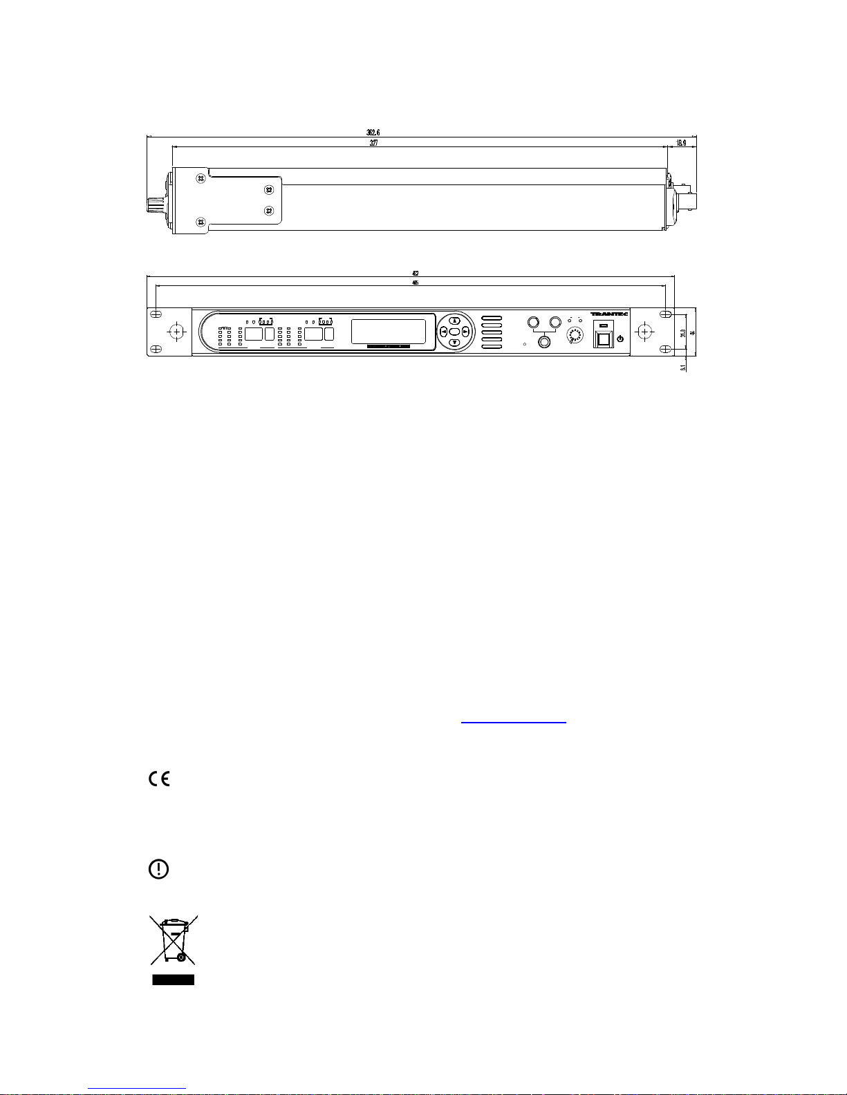
Dimensions: 482 x 44 x 362.6 mm (1U)
Weight : 4 kg
21
14. Accessories Included
AC Power Cord (UK use only)
2 x Antenna (direct-mount type)
Antenna mounting kit:
2 x MB-15B brackets (fitted)
8 x M3x8 screws (fitted)
4 x M5 screws and washers
2 x BNC to BNC antenna distribution cables
4 x rubber feet
2 x blanking plugs
Software CD
Manual
For more information on this and other products, go to www.trantec.co.uk
Declaration of Conformity
This equipment is in compliance with the essential requirements and other relevant provisions
of Directives 1999/5/EC, 89/336/EC or 73/23/EC.
IMPORTANT NOTICE
Before using this wireless microphone system, please observe the requirements of each
country with respect to frequency allocations and individual licensing requirements.
This symbol indicates that this piece of electrical/electronic equipment must be
disposed of separately from normal waste at the end of its operational life. Please
dispose of this product by taking it to your local recycling or collection point.
AF
dB
0
-9
-18
-27
-36
300
100
30
10
A BµV
RF
ANT BATT
A B
E F
RF
A B
1000
300
100
30
10
0
-9
-18
-27
-36
AF
µV dB
ANT
A B
BATT
E F
GROUP CHGROUP CH
UNIT 1 UNIT 2
UNIT 1 UNIT 2
UNIT1 2
VOL
MIN MAX
OUTPUT
BAND
ANT ATT A
ANT ATT B
RF CASCADE
LAN
LAN RESET
DIGITAL WIRELESS TUNER S-D7802
1 2
0 -10 -20
0 -10 -20dBdB
ANT A ANT B
FULL/COL
REMOTE LINK/ACT
SET
PHONES
Rev 1.1
 Loading...