

UHF
WIRELESS
SYSTEM
UHF
WIRELESS
SYSTEM
OPERATING
MANUAL
S4
.
4
BBM Electronics Group Limited
Kestrel House . Garth Road . Morden
Surrey . SM4 4LP . England
Telephone: +44 (0) 20 8330 3111
Facsimile: +44 (0) 20 8330 3222
www.trantec.co.uk
back cover
S4.4 ARTWORK 17/2/06 11:29 am Page 1
CONTENTS
Introduction and Safety
Trantec S4.4 System Overview
Receiver Layout and Operation
Handheld Layout and Operation
Beltpack Layout and Operation
General Set-up and Operating Hints and Fault Finding
System Contents Description and System Part Numbers
Technical Specifications
Warranty Terms
1.
2.
3.
4.
5.
7.
9.
10.
12.
print black on throughout. cover, 2/1 x 4pp. Text 1/1 x 12pp
S4.4 ARTWORK 17/2/06 11:29 am Page 3

INTRODUCTION
The Trantec S4.4 Series represents Trantec's commitment to providing highquality, affordable Wireless Audio Links using our considerable design
expertise gained over many years as a leading edge manufacturer.
We would like to thank you for purchasing this product and would like you to
spend a short time reading this Operations Manual so as to familiarise yourself
with the features of the Trantec S4.4 series.
SAFETY
Our aim is to supply you with a product that provides you with countless
hours of trouble free use.
In order to achieve these goals, we recommend the following:-
Keep the system away from direct sources of heat e.g. Central heating
radiators, heaters and direct sunlight.
Should the Transmitters not be used for extended periods of time we
recommend that the batteries should be removed so as to avoid any
potential battery leakage.
Keep the system clean by using a slightly damp cloth. Never use household
cleaning agents or solvents.
Avoid using or storing the system in damp conditions.
Always use the AC power adaptor supplied with the Receiver and never
remove the external covers of the equipment, so as to expose the
electronics.
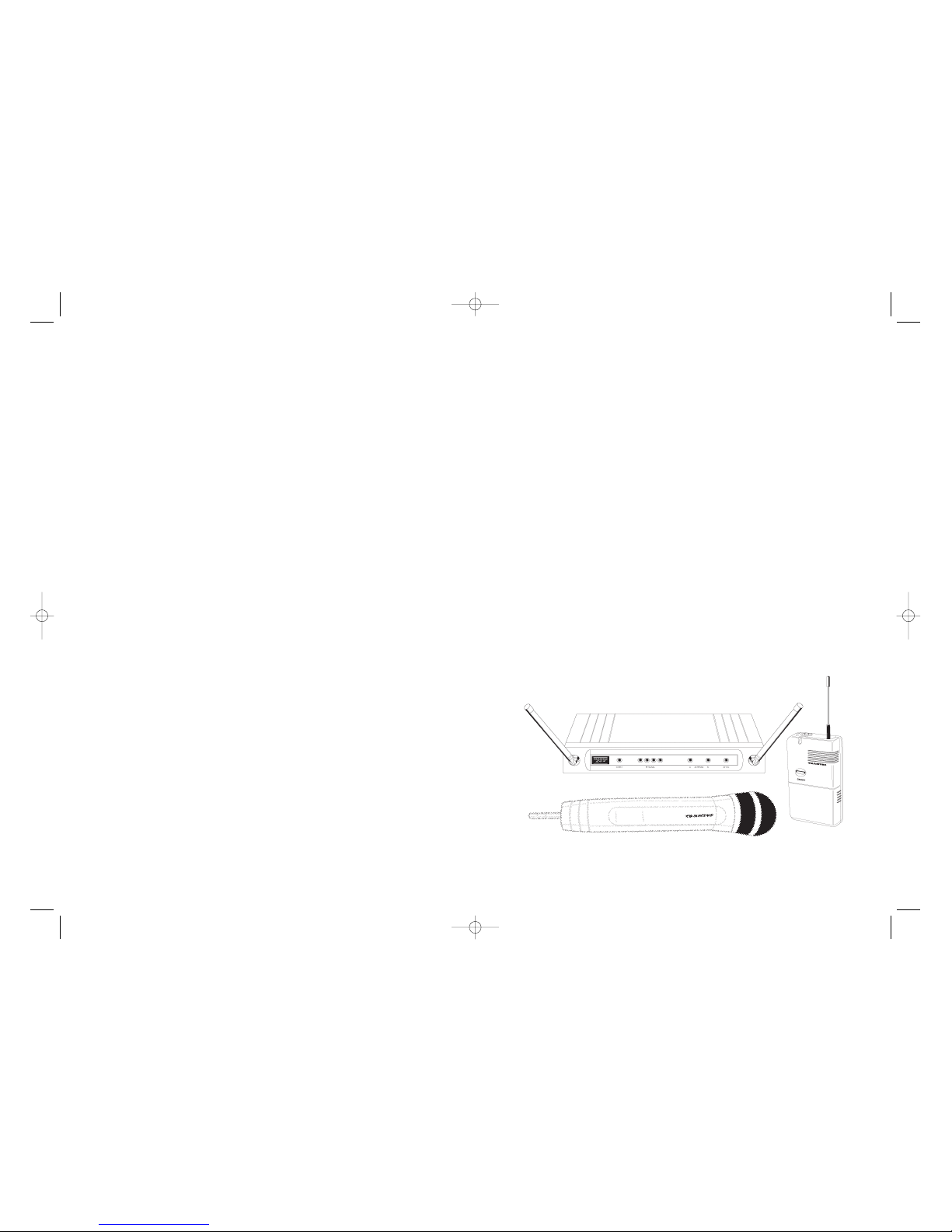
S4.4 SYSTEM OVERVIEW
The Trantec S4.4 is a high-quality UHF Wireless Microphone System.
The S4.4 has many features including:-
>> 4 User Selectable Channels - that can be operated simultaneously.
>> Diversity Receiver Operation - to minimise drop-outs
>> User Adjustable Audio Output Level - adjustable on both Jack and
XLR outputs.
>> User Adjustable RSSI/Squelch - enables the user to minimise external
interference.
>> Designed to operate license free in most EU countries.
(EA Band 863-865 MHz)
THE S4.4 COMPRISES OF 2 BASIC DIFFERENT VARIATIONS:-
The Handheld System and the Beltpack Presenters/Instrument System.
The Handheld System comprises of a fully integrated Handheld Microphone
incorporating a Cardioid Dynamic Capsule and is most suited to General
Vocal Applications.
The Beltpack System comprises of a Beltpack Transmitter which is supplied
with a small Lapel style clip-on Microphone and is ideally suited for General
Presentation/ Theatre applications.
In addition the Beltpack Transmitter is supplied with a Instrument Cord. This
cord enables the beltpack to be used with electric instruments e.g. Guitars
and other high impedance applications.
1 2
S4.4 ARTWORK 17/2/06 11:29 am Page 5

S4.4 RECEIVER LAYOUT
RECEIVER OPERATION
1. Connect the appropriate AC adaptor into the DC inlet as marked on the
rear panel and observe the Supply indicator (green Led ) lights up.
2. To provide best diversity operation, angle the antennas to form a ”V” as
per illustration and ensure that the antennas have a good line-of–sight
view of the corresponding transmitter. i.e. Avoid placing large metallic
objects in the transmission path.
3. Initially set the receiver AF gain control to its mid-position and connect
the AF output from either the
1/4 inch Jack or XLR to your Mixing console
or amplifier.
4. Select rear panel Channel Selector Switch (Small screw-driver adjust)
to correspond to Transmitter setting. It is possible to select any of the 4
channels. (Factory set to position 1).
S4.4 HANDHELD LAYOUT
HANDHELD BATTERY INSERTION
1. Rotate the top collar locking ring in the
direction indicated in the illustration
and gently pull the body downwards.
2. Insert a 9V MN1604 (IEC 6 LR61) PP3 type
alkaline battery, being sure to observe the
correct polarity as marked.
3. Gently slide the body upwards and lock.
Note: Should the Red battery status Led Indicator go out
during operation, this indicates a flattened battery and
should be changed .
CHANNEL SELECTION. (Small screw-driver adjust)
With the Transmitter in the OFF position select a channel to correspond with
the Receiver. It is possible to select any of the 4 channels.
(Factory set to position 1).
Note: The Transmitter only changes Active Channel when turned off and then on.
3 4
DIVERSITY A
ANTENNA A
ANTENNA B
POWER
RF SIGNAL
LEVEL
AUDIO
OUTPUT XLR
AC
ADAPTOR
INLET
CHANNEL
SELECTOR SWITCH
AUDIO
OUTPUT JACK
AUDIO
OUTPUT
LEVEL
MUTE/
SQUELCH
CONTROL
AF PEAK O/L
DIVERSITY B
{
ON/OFF
CHANNEL
SELECTOR
GRILLE
LOCKING RING
ANTENNA
BODY
BATTERY
STATUS
INDICATOR
S4.4 ARTWORK 17/2/06 11:29 am Page 7

S4.4 BELTPACK LAYOUT
BELTPACK BATTERY INSERTION
1. Slide the battery compartment to the rear and hinge up-wards to expose
the battery.
2. Insert a 9V MN1604 (IEC 6 LR61) PP3 type alkaline battery, being sure to
observe the correct polarity as marked.
Note: Should the Red battery status Led Indicator go out during operation, this
indicates a flattened battery and should be changed .
MICROPHONE CONNECTION
1. Connect small lapel-type microphone into the corresponding 3.5mm Top
Panel Socket.
2. Ensure that the Battery Compartment MIC/INST switch is set to
Mic position.
3. Clip the microphone to your clothing (normally Tie or Jacket Lapel). Route
the mic cable so as to avoid undue strain or friction. Try and keep the mic
cable away from the ANTENNA
The microphone supplied with the S4.4 as a Omni-directional response,
which means it will pick up sounds from all directions. In view of this we
recommend that the microphone is placed as close as possible to the required
sound source.
INSTRUMENT CONNECTION
1. Connect the supplied Instrument cord into the corresponding 3.5mm Top
Panel Socket.
2. Ensure that the battery compartment MIC/INST switch is set to
INST position
BELTPACK GAIN CONTROL ADJUSTMENT. (Small screw-driver adjust)
If required adjust the Transmitter AF gain control so as the signal only very
occasionally allows the Red AF O/L Peak Led on the receiver to light.
CHANNEL SELECTION (Small screw-driver adjust)
With the Transmitter in the OFF position, select a
channel to correspond with the Receiver. It is
possible to select any of the 4 channels.
(Factory set to position 1).
Note: The Transmitter only changes Active
Channel when turned off and then on.
5 6
ROTATING
BELT
CLIP
BATTERY
STATUS
INDICATOR
BATTERY/
CONTROL
HOUSING
AUDIO
INPUT
ANTENNA
LP2
LAPEL MICROPHONE
ON/OFF
SWITCH
AF GAIN ADJUST
CHANNEL SELECT
MIC/INSTRUMENT SWITCH
S4.4 ARTWORK 17/2/06 11:29 am Page 9

GENERAL SETUP AND OPERATING HINTS
1. DISTANCE.
To maximise operating distance (approximately 100m). We recommend
you follow the following guidelines.
a. Ensure good line of sight between Transmitter and Receiver. Do not place
large obstructions between receiver and transmitters e.g. Concrete walls,
large metal obstructions. In addition keep the receiver away from metallic
beams and obstructions as these can adversely affect the Antenna Pick-up
Pattern and induce interference.
b. Always ensure that the Transmitter is at least 3m (10 feet) away
from the Transmitter.
c. Conduct a “Walk test” which involves you moving the Transmitter in the
area transmission is required and noting the received RF signal strength on
the receiver bargraph. Reception is best with all 4 Leds lit.
d. Never position the Transmitter Antenna directly against the body or hand.
This will have the effect of reducing the operating range considerably.
2. MULTICHANNEL OPERATION OF THE S4.4.
The S4.4 is designed for simultaneous use of four systems.
a. Ensure each system is assigned a different operating channel. The
channels are adjusted as per the illustrations. It is important that each
Transmitter/Receiver combination has it’s own unique channel numbered 1-4.
Note: The Transmitter only changes Active Channel when turned off and then on.
b. We recommend that the Receivers are spaced slightly apart and not stacked
directly on top of each other to avoid disturbance to the Receivers
Antennae.
c. Try to ensure that each Transmitter is separated by 0.5m (1.5 feet) during
operation.
Note: Trantec cannot guarantee multichannel compatibility with other brands/make
of product.
3. SQUELCH/RSSI SET UP.
The S4.4 incorporates a Fixed Noise Squelch and a variable “Received
Signal strength” Mute Control on the rear panel of the Receiver. This
function is to reduce or eliminate the effect of interference from
outside sources.
To adjust follow these steps:
a. Turn-off the Transmitter and note if any interference is present by
monitoring the Receiver RF Bargraph or Audio Output.
b. Turn the Squelch Control clockwise until the interference disappears.
In extreme cases it may not be possible to remove the unwanted
interference and in this case it is recommended you try an alternative
channel.
Note: that the Squelch Control affects the operating range of the system and with the
Squelch set to maximum, the range will be significantly reduced.
4. RECEIVER AF GAIN ADJUST.
The S4.4 receiver gain is continuously adjustable between Mic and
Line level.
Should the receiver signal be too high it will distort your mixer/amplifier.
If the signal is too low the result will be an increase in general
background noise.
Adjust this control to achieve the best signal quality.
5. BATTERY INFORMATION.
Please note that this product is designed to be used with a 9V Alkaline
battery. Should you use a rechargeable cell, be sure not to force it into the
battery compartment as some types can be considerably larger than
standard types and note that the operation time will be much reduced.
6. LOW-BATTERY STATUS INDICATOR ON TRANSMITTERS.
In normal circumstances, with the use of an Alkaline 9V battery, the
Transmitters should provide approximately 10hrs of continuous use.
Should the Battery indicator go out, it is advisable to change the battery
as soon as possible.
FAULT-FINDING.
In the event of a problem it is worth checking the following check list.
1. No RF Signal Indication on Receiver!
a. Is the Receiver and Transmitter on the same channel?
b Is the battery fresh in the Transmitter and the battery indicator lit?
2. No Audio Signal!
a. Is the AF Gain Control set correctly on the Receiver?
b. Is the Squelch Control set correctly (Normally mid-position).?
c. Is the MIC/INST switch in the correct position on the Beltpack?
Handh
It is ad
Handh
the fo
Remov
directio
sule.
Remov
grille a
small b
Do no
7 8
S4.4 ARTWORK 17/2/06 11:29 am Page 11

S4.4L SYSTEM:
S4.4RX Receiver
S4.4LTX Beltpack Transmitter
PSU Mains AC adaptor
LP2 Lapel type microphone
GC2 Instrument cable
S4.4BK Instruction manual.
SYSTEM PART NUMBERS
S4.4M SYSTEM:
S4.4RX Receiver
S4.4MTX Handheld Transmitter
PSU Mains AC adaptor
MA2 Microphone stand
mount/adaptor
S4.4BK Instruction manual.
TECHNICAL SPECIFICATIONS:-
OVERVIEW.
Fully synthesised 4 channel PLL Quartz Controlled FM Wireless Microphone
System incorporating a Dual Conversion Diversity Receiver with Integral Audio
Dynamics Processor.
OPERATING FREQUENCIES:
Band EA 863.150, 863.725, 864.150, 864.850MHz
Band UH 742.075, 742.800, 743.300, 743.975MHz
Band UL 719.025, 719.600, 720.450, 720.875MHz
AF S/N RATIO: > 96dBA
AF FREQUENCY RESPONSE: Handheld 80Hz – 16KHz +/- 3dB.
Beltpack 60Hz - 16KHz +/- 3dB
AF THD: less than 1%
OPERATING TEMPERATURE RANGE:
-10
0
- +450C / 95 relative humidity.
RECEIVER
OPERATING VOLTAGE: 12V @ 100mA
FIRST IF FREQUENCY: 55.875MHz
SECOND IF FREQUENCY: 10.700MHz
AF OUTPUT: Variable to +10dBu unbalanced via
1/4 inch mono Jack
socket.
+16dBu Balanced via XLR 3F connector Pin 2 +.
INDICATORS: 4 position RF Bargraph, AF peak (overload), Power,
Diversity A/B.
CONTROLS: Channel select, AF output, Squelch.
DIMENSIONS: 35 x 213 x 98mm.
WEIGHT: Approx 580g
BELTPACK DESCRIPTION
S4.4L–EA–UK 863-865MHz
UK Power supply
S4.4L–EA–EU 863-865MHz
EU Power supply
S4.4L–UH–UK 742-744MHz
UK Power supply
S4.4L–UH–EU 742-744MHz
EU Power supply
S4.4L–UH–US 742-744MHz
US Power supply
S4.4L–UL–UK 719-721MHz
UK Power supply
S4.4L–UL–EU 719-721MHz
EU Power supply
S4.4L–UL–US 719-721MHz
US Power supply
HANDHELD
S4.4H–EA–UK 863-865MHz
UK Power supply
S4.4H–EA–EU 863-865MHz
EU Power supply
S4.4H–UH–UK 742-744MHz
UK Power supply
S4.4H–UH–EU 742-744MHz
EU Power supply
S4.4H–UH–US 742-744MHz
US Power supply
S4.4H–UL–UK 719-721MHz
UK Power supply
HANDHELD DESCRIPTION
S4.4H–UL–EU 719-721MHz
EU Power supply
S4.4H–UL–US 719-721MHz
US Power supply
INDIVIDUAL COMPONENTS PART
NUMBERS
S4.4LTX–EA 863-865MHz
BeltpackTransmitter
S4.4LTX–UH 742-744MHz
Beltpack Transmitter
S4.4LTX–UL 719-721MHz
Beltpack Transmitter
S4.4MTX–EA 863-865MHz
Handheld Transmitter
S4.4MTX–UH 742-744MHz
Handheld Transmitter
S4.4MTX–UL 719-721MHz
Handheld Transmitter
S4.4RX–EA 863-865MHz
Receiver
S4.4RX–UH 742-744MHz
Receiver
S4.4RX–UL 719-721MHz
Receiver
S4.4PSU–UK Power supply UK
S4.4PSU–EU Power supply EU
S4.4PSU–US Power supply US
S4.4 SYSTEM PACKAGE CONTENTS
9 10
S4.4 ARTWORK 17/2/06 11:29 am Page 13

HANDHELD TRANSMITTER
OPERATING VOLTAGE: 9V @ <50mA.
OPERATING TIME: approx 10 hours.
OUTPUT POWER: 10mW max.
CONTROLS: Frequency select, On-off switch.
INDICATORS: Battery status Led.
TRANSDUCER TYPE: Dynamic with Cardioid pattern.
DIMENSIONS: 280 x 50mm max. (including grille)
WEIGHT: Approx 210g
BELTPACK TRANSMITTER
OPERATING VOLTAGE: 9V @ <50mA.
OPERATING TIME: approx 10hours.
OUTPUT POWER: 10mW max.
CONTROLS: Frequency select, On-off switch, Lapel/Instrument
switch, Gain adjust.
INDICATORS: Battery status Led.
CONNECTORS: AF input via 3.5mm socket.
Tip = Audio.
Ring + sleeve = Gnd.
LP2 LAVALIER
MICROPHONE: Back electret condenser
microphone with omni-directional pattern.
DIMENSIONS: 60 x 100 x 30mm mm including belt clip.
WEIGHT: Approx 90g
TYPE APPROVALS. ETSI 300-422, FCC pt 74 h.
NOTES
DECLARATION OF CONFORMITY:
This equipment is in compliance with the essential requirements and other
relevant provisions of Directives 1999/5/EC, 89/336/EC or 73/23EC.
More information available at: www.trantec.co.uk
GUARANTEE:
All Trantec products are guaranteed for a period of one year from date of
purchase against defects in materials and workmanship. In the event of a claim
under guarantee the system should be returned to your dealer in its original
packaging and with proof of purchase. Defects caused by modification, misuse or accident are not covered by this guarantee.
E&OE Due to our continual policy of research and development we reserve the
right to alter specifications without prior notice.
01/06
Part Number: S4.4BK
Printed in Taiwan
11 12
S4.4 ARTWORK 17/2/06 11:29 am Page 15
 Loading...