


The world’s finest wireless systems
TOA Corporation (UK) Limited
HQ3 Unit 2, Hook Rise South,
Surbiton, Surrey, KT6 7LD, England
Telephone: +44 (0) 870 774 0987
Fax: +44 (0) 870 777 0839
Email: sales@trantec.co.uk
www.trantec.co.uk
IEM S4.16
Professional in-ear Wireless Monitoring System

Thank you for choosing Trantec professional wireless
in-ear monitoring system
1. Features
The Trantec IEM S4.16 is designed for live performances and audio broadcast so
that the user can maximize the overall monitoring experience without the use of
large and complicated monitoring loudspeakers. Also the system can be used in
a conference application with multi language translation. The Trantec IEM S4.16
adopts a dynamic processing technique that improves the audio quality and
signal to restrain unwanted noise.
2. Product Introduction
The Trantec IEM S4.16-TX is a stereo UHF transmitter and in every 24 MHz there
are 16 preset frequencies. The main features are as follows:
a) LCD Panel
b) Standard 19/2 metal mainframe
c) Balanced and unbalanced input jack
d) Optional stereo and mono channels
e) With PLL synthesized technology
f) With compressing and expanding circuitry, S/N is over 90dB
g) Built in limiting circuitry to avoid distortion in case of overload
h) Phone output monitoring jack
The Trantec IEM S4.16-RX is a stereo receiver complete with 16 preset
frequencies in every 24 MHz utilising the most advanced circuitry design and is
the ideal choice among professional performers.
1

Main Features;
UHF professional stereo receiver
PLL synthesized technology, 16 optional preset frequencies
in its band width of 24 MHz
Optional stereo and mono channel function
Power indicator and RF signal
Compression and expander circuitry with S/N over 90dB
AA batteries x 2
Flexible antenna
3. System Components
IEM S4.16-TX transmitter x 1
Power supply x 1
Antenna x 1
1.5 AA batteries x 2
IEM S4.16-1RX receiver x 1
Stereo headphones x 1
Waterproof bag x 1
1
3
7
6
2
1
5
4
2
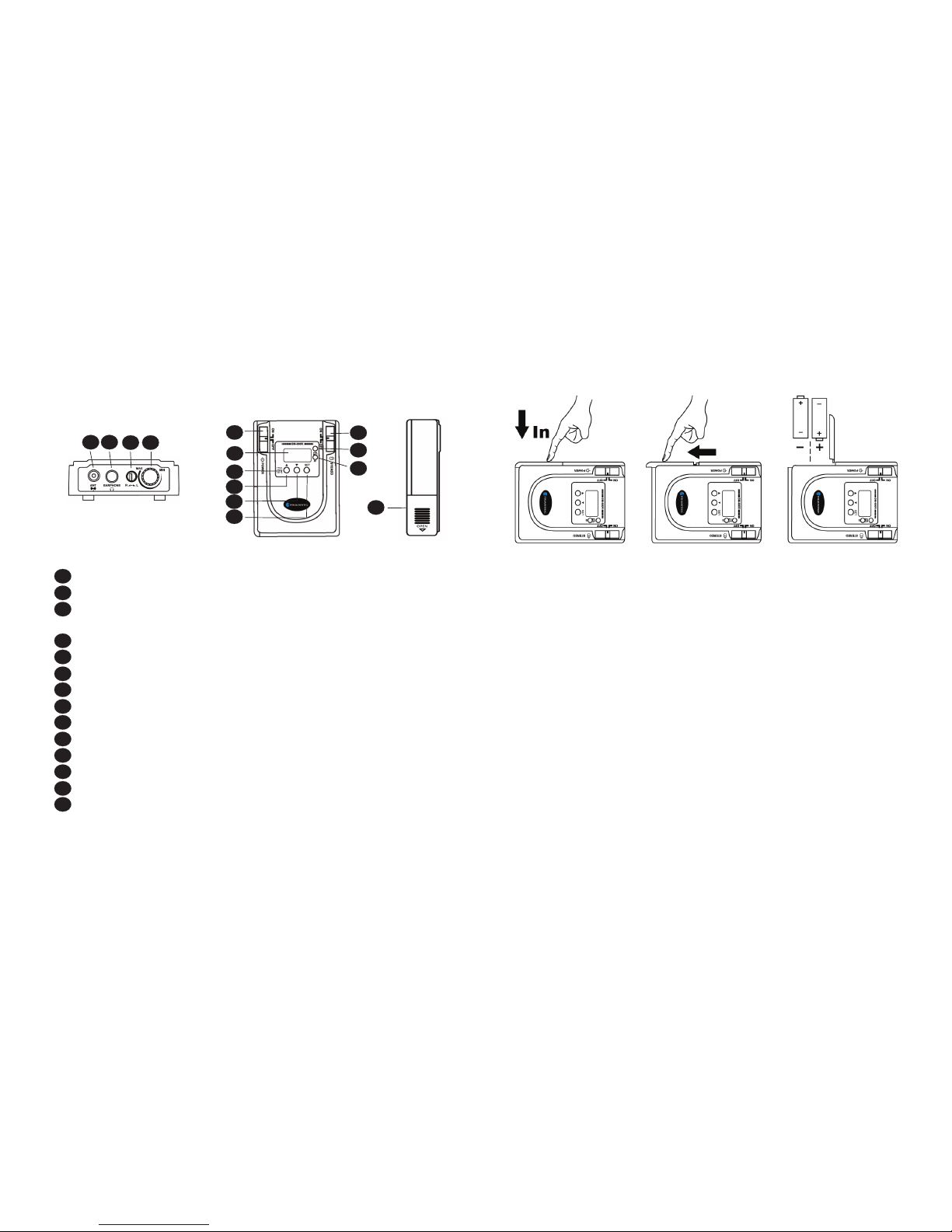
4. Function Instructions
1
2
3
4
5
6
7
8 9
1
0
11
12
1
3
14
1
5
Front Panel
Rear Panel
1
2
3
4
5
6
7
8
9
10
11
12
13
14
15
Power switch and power indicator
Up
Down
Set
Headphone output jack, with stereo monitoring signal
LCD
Window of infrared data transmission
Antenna connector
High and Low RF switch
Left Channel unbalanced output
Right Channel unbalanced output
Left Channel input: balanced and unbalanced
Right Channel input: balanced and unbalanced
DC power input
Cable fix
3
6
5
4
3
2
7
2. IEM S4.16-RX
1
2
3
4
5
6
7
8
9
1
0
11
12
13
1
4
1
2
3
4
5
6
7
8
9
10
11
12
13
14
1/4 wave antenna
3.5 stereo monitoring headphone output
Left and right hand channel balanced adjusting button allowing the
adjustment volume of left and right channels
Volume control
Power switch
LCD
Infrared data transmission window
UP
DOWN
SET
Optional switch, stereo and mono channels
Low power indicator
RF signal indicator
Battery cover
4
3. Battery Installation
(1) Put the power switch to OFF and press the open side of the battery cover
. and slide to open cover
(2) Place two pieces of AA batteries (1.5V) with the correct polarity
(3) Close the battery cover
(4) Switch power to ON and the LCD will display showing that the CPU receiver
. is working and the hardware is initializing and recovering the last working .
. condition before power down.
5
4. Installation
(1) System Installation
LOOP Applications
Use the Loop OUT L (left) and R (right) outputs to send a copy of the audio signal
going into the transmitter to other devices. Shown here are a few examples of the
many configurations for the LOOP outputs.
NOTE: The input level control and the input pad do not affect the level of
the LOOP signals.
Stereo for multiple Systems
Use the LOOP OUT connectors to send one stereo signal from the mixing console
to multiple IEM 4.16-RX wireless transmitters. This frees up outputs on the mixing
console for other uses.
Connect the first transmitter to the mixer.
Connect the next transmitter to the first transmitter‘s LOOP outputs. Form
a chain using all transmitters in your installation.
IEM S4.16-RX
IEM S4.16-RX
IEM S4.16-TX
IEM S4.16-TX
IEM S4.16-TX
67
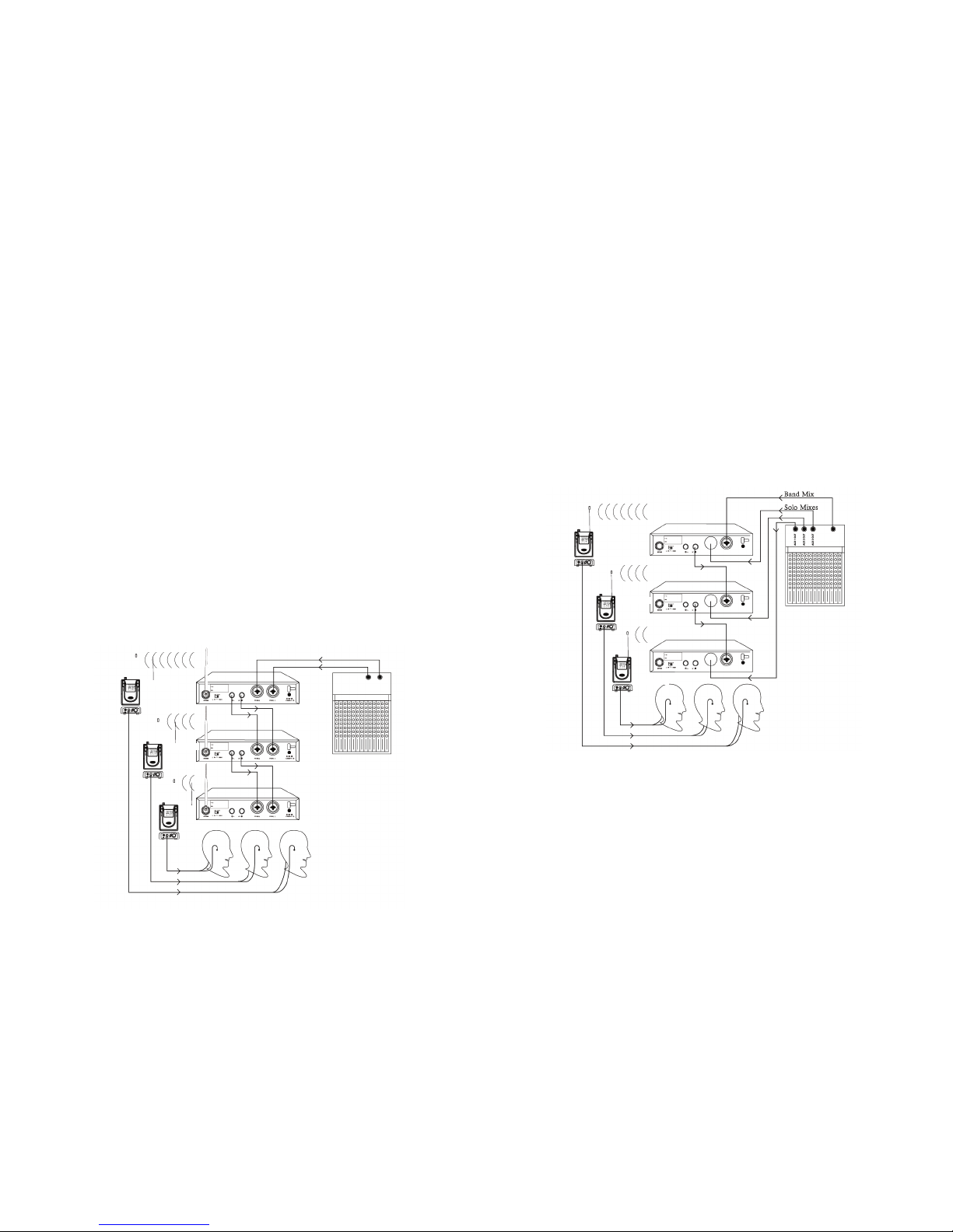
Mix Mode for Multiple Systems
Some performers need to hear more of their own voice or instrument while others
want to hear more of the band. With this setup, each performer hears a
combination of the whole band and their own instrument and the performer can
use the receivers balance control to create the desired mix of the whole band to
input 2 of the first transmitter. Connect input 2 of the next transmitter to the
LOOP OUT R output of the first transmitter. Continue the chain with all the
transmitters. Next, create sole mixes for each performer using the auxiliary
outputs of the mixing console. Send these mixes to input 1 of each performers
transmitter
IEM S4.16-RX
IEM S4.16-RX
IEM S4.16-RX
IEM S4.16-TX
IEM S4.16-TX
IEM S4.16-TX
IEM S4.16-RX
(2) Power Installation
Connect the output port of the DC12V-15V/800mA to the input of the DC
Power of the transmitter.
(3) Turn On Power
Press the power button and the LCD will illuminate, meanwhile more
information will be displayed and will output the transmitting
signal once the PLL circuitry is locked

89
(4) Audio Signal Input
Optional stereo and mono channel input, mono channel input from AF II IN of the
right side, you can choose XLR-3 balanced input or 6.3 unbalanced input
connector.
(5) Configuring Suitable Audio Input Standard
The strength of the audio input signal will be display on the LCD panel, you
can set the strength to show 8 bars and when the strength is over the 8
bars the input signal will be limited even when the signal is stronger. By
doing this you can obtain the best S/N ratio and dynamic range by
adjusting the input strength to avoid distortion.
(6) Setting Frequency of the Transmitter
a. Press the UP and DOWN button, the system will change the frequency
and channel according to the preset menu. When the LCD displays the
frequency the channel will also change. When the name appears the
system is changing automatically according to the frequency or channel.
b. Press UP and DOWN button to the desired frequency or channel you re
quire. The frequency or chanel you have chosen will begin to flash
c. Press SET button and the frequency or channel has been fixed and the
CPU will lock the frequency the LCD will stop flashing and will revert to
it’s orignal status.
Select Frequency Panell
Changing Frequency Save Frequency
(7) Steps to configure The Stereo Channel and Mono Channel
a. Press SET to scroll through the options until the units dislpays “input
mode”
b. Press SET and the LCD will display “stereo”, press SET to
confirm
c. Press SET and the LCD will display “mono”, press SET to
confirm
(a)
(c)
(b)
(8) Configuration of Lock Function
a. Press SET to scroll trough the options until the unit displays LOCK
b. Pess DOWN to confirm and the LCD will display LOCK OFF to confirm
c. Press DOWN, the LCD will display LOCK ON, showing that the setting
function is locked and you can not modify the functions until you relieve
change to release
d. Press SET to confirm your choice
(a)
(c)
(b)
(d)

10 11
(9) Configuration of Input Sensitivity
a. Press SET to scroll through the options until the unit displays SENSITIVE
b. Press SET and HIGH will be displayed to show that the sensitivity is high
c. Press DOWN, the LCD will display LOW, showing that the input
sensitivity is low
d. Press SET to confirm your choice
(a)
(c)
(b)
(10) Configuration of Display
a. Press SET to scroll through th eoptions until the unit displays DISP MODE
b. Pess SETT to confirm and DISP FREQ will be displayed to show
frequency
c. Press DOWN, the LCD will display DISP CHAN to show channel
d. Press DOWN, the LCD will display DISP NAME to show name
e. Press SET to confirm your choice
(a)
(c)
(b)
(d)
(11) Name Configuration
a. Press SET to scroll through the options until the unit displays
RENAME, then press SET to confirm
b. Press DOWN and AAA will be displayed, press DOWN to set letters or
numbers
c. Press SET to move to the last setting of character and repeat the
operation of b and c to finish the setting of 8 characters
(a)
(c)
(b)
(12) Configure Monitor Volume
a. Press SET to scroll through th eoptions until the unit displays
PHONES VOL, it will display -40dB, then press DOWN again, the
monitoring output volume will decrease
b. Press SET to confirm your choice
c. Press UP and the monitoring volume will increase
(a)
(c)
(b)
NOTE: to protect your hearing, please adjust the volume to avoid distortion

12 13
(13) Receiver LCD
1) All the menus will be displayed here
2) Display of the battery power is divided into 4 bars and when there is only one bar
left, it means the battery power is running low and you should change the batteries
(14) Headphone Connection
Insert the stereo monitoring headphone to 3.5mm headphone jack socket, or
connect the output to an audio input of another device
Notice: This 3.5mm jack socket is a stereo output, please make certain
that the connection is a stereo jack otherwise it is possible that damage could be
caused to the output circuit.
(15) Setting the Receiver Frequency
Press
or
to show changing of the frequency and press SET to confirm
(16) Configuration of Display of the Receiver
a. Press SET and press
b.Press SET to confirm and
will be displayed. Press again to display
frequency
c.Press
to show
and press SET to display channel
(a)
(c)
(b)
(17) Setting the Lock Function
a. Press SET
and press
to show
b. Press SET to confirm and LCD will display
meaning the lock function
has been relieved to release
c. Press to show and press SET, the setting function has been locked
(a)
(c)
(b)
(a)
(c)
(b)
(18) Configuration of Receiver Signal
a. Press SET to show
and press SET to show
b. Press SET to confirm, LCD will display the former data of SQ such as
c. Press UP or DOWN, the mute level will change and you can choose the level
required
(19) Switch for Sound Mode
To choose the current headphone output for stereo or mono channel, it should
be consistent with the transmitter
Notice: when choosing the stereo sound mode, you will have better
sound behavior but an increase in S/N when choosing single output mode, the
S/N will be larger and will increase distance

14 15
6. Notice
(1) When this system is being used together with a wireless
microphone system, please avoid the same frequency range to prevent distortion
(2) Please make sure that there are no obstacles between the antenna of the
transmitter and the receiver. When used indoors the obstacles will absorb wave form
that will shorten the transmission distances
(3)Connect the transmitting signal to the external antenna with coaxial cable, the
coaxial cable should be 50Ω, generally 5 meters RG-58
(4) The working life time for the battery depends on the output volume power of the
headphone and choosing a headphone with better sensitivity will increase battery life
(5) The voltage of the power supply should exceed 12V and less than 18V while
making sure that the output current is over 500mA
(6) Please remove the batteries when not in use over a long period of time.
F
requency range (606.250 - 613.850) (863 - 864.870)
Band width 24MHz
Oscillation PLL synthesized
Channel separation interval 25KHz
F
requency stability ±0.005% 0°C-50°C
M
odulation mode FM stereo
M
ax deviation ±68KHz
F
requency response 80Hz -15KZ ± 3DB
Stereo separation >45dB (at 1KHz)
Output jack ∅ 3.5mm stereo headphone jack
Power AA battery x 2
Battery life 8 hours (under normal operating conditions)
Antenna Fixed 1/2
Dimensions 88 (L) x 65 (W) x 32 (H)
Weight 105g
IEM S4.16-RX
Frequency range (606.250 - 613.850) (863 - 864.870)
Band width 24MHz
Oscillation PLL synthesized
Channel separation interval 25KHz
Frequency stability ±0.005% 0°C-50°C
Modulation mode FM stereo
Transmitter output power low<10mW high<100mW
Spurious rejection <4nW
Stereo separation >45dB (at 1KHz)
Maximum deviation range ±40KHz
Frequency response 50-15KHz ±3dB
Audio input line level x 2 XLR ∅ 6.3mm combined jack
Audio output ∅ 6.3mm jack x 2
Dimensions 210 (L) x 206 (W) x 44 (H)
Rating power 5W
Weight 1.1Kg
IEM S4.16-TX
Type Stereo in-ear
Diameter ∅ 9mm
Sensitivity 104±dB/mwatt 1 KHz
Impedance 16Ω
Frequency response 20Hz - 22KHz
Rating power 2mW
Max power 10mW
Jack ∅3.5mm
Headphones
7. Specification
 Loading...