

Page 1
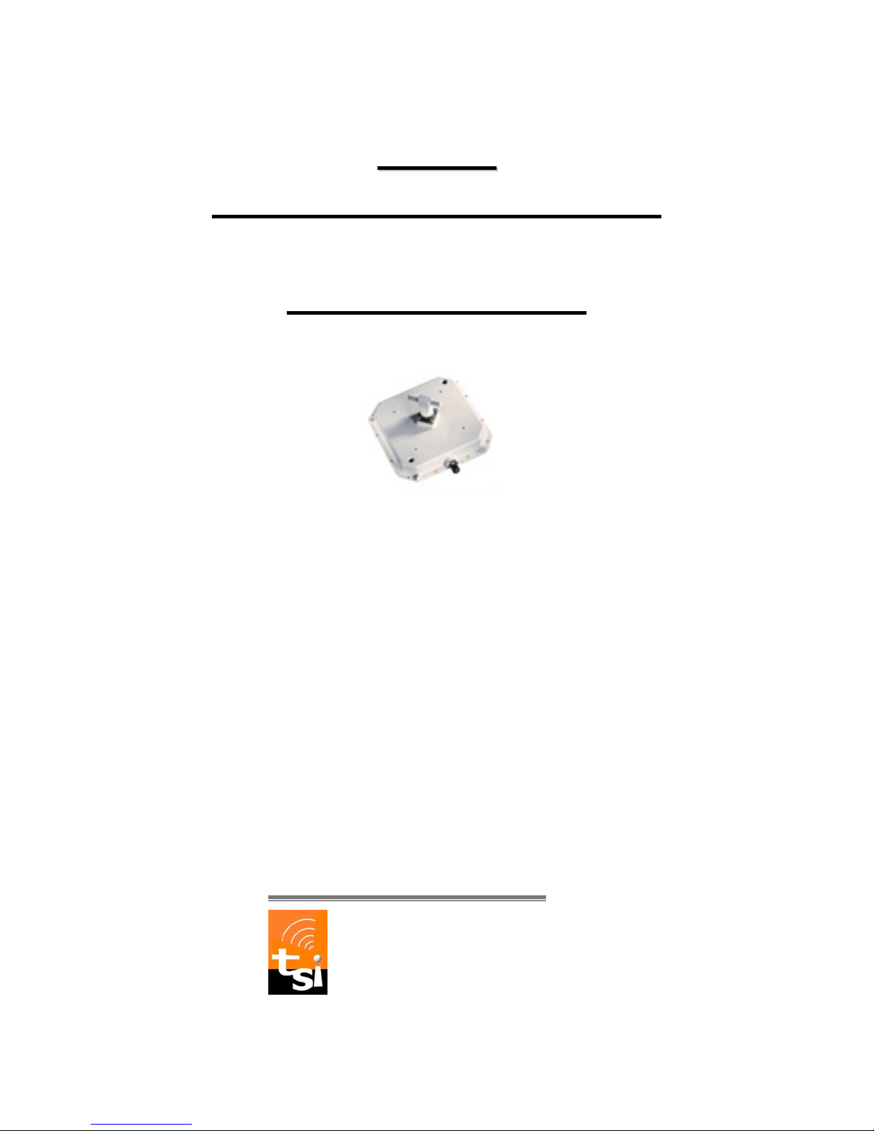
MMDS
MMDS
Transmitter: PL-12-1-28ND
Operation Manual
Copyright 2008, TRANSYSTEM, INC.
All rights reserved
TRANSYSTEM INC.
No.1-2 Li-Hsin Rd.I Science-Based
Industrial Park, Hsinchu, Taiwan
Tel:+886-3-5780393 Fax:+886-3-5784111
e-mail: [email protected]
website: www.transystem.com.tw
1
Page 2

2
TABLE OF CONTENTS
Chapter 1. General Information 4
1.1 Module Features and Specifications 4
Chapter 2. Installation 5
2.1 Step by Step Installation 5
2.2 Connection to the Power Inserter and Cable Modem 8
2.3 Waterproofing Connections 10
Chapter 3. Accessories 12
3.1 MMDS Antenna 12
Page 3
3
Chapter 1. General Information
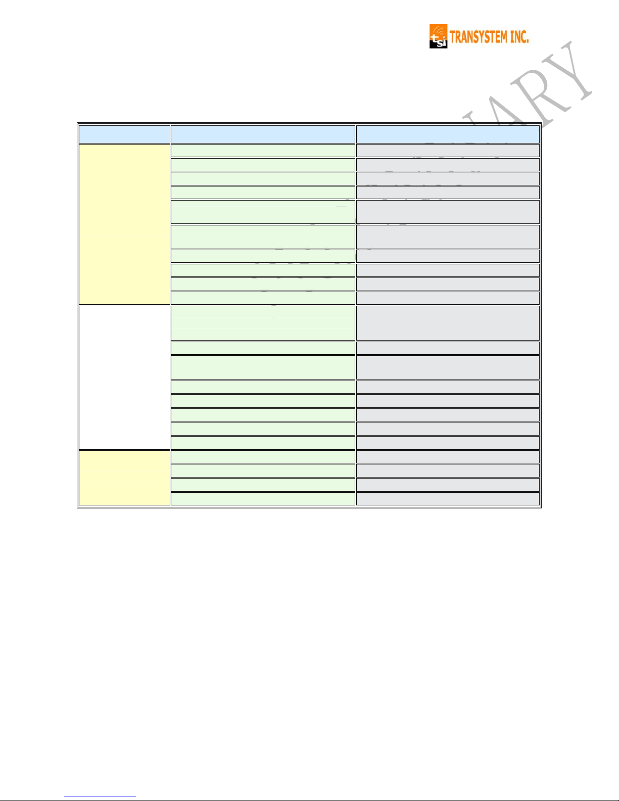
1.1 Module Features and Specifications
Category Parameter Description
IF Input 12 ~ 42 MHz
RF Output 2500 ~ 2530 MHz
Gain 24 ± 2 dB
Output 1-dB Compression Point +24 dBm typical
Output Transmit Noise
-120 dBm/Hz typical
-118 dBm/Hzm ax
Output Spurious
@+22 dBm Tx output
-60 dBc
( in-band and out-band )
Output Power Blanking Threshold -45 dBm @ IF input
TX Switch Latency < 1.2 micro second
Upstream
Phase Noise
-84dBc/Hz @ 1KHz
-88 dBc/Hz @ 10 KHz
-96 dBc/Hz @ 100 KHz
LO Leakage at RF / IF ports -50 dBm Max.
LO Frequency
Downstream : 2278 MHz
Upstream : 2488MHz
LO Stability ± 10 KHz over temp.
General
Other feature:
1. lightning protection Ok
2. surge protection Ok
3. Transmitter sleep mode Ok
Note: Typical value @25℃, unless otherwise specified.
Page 4
Chapter 2. Installation
2.1 Step by Step Installation
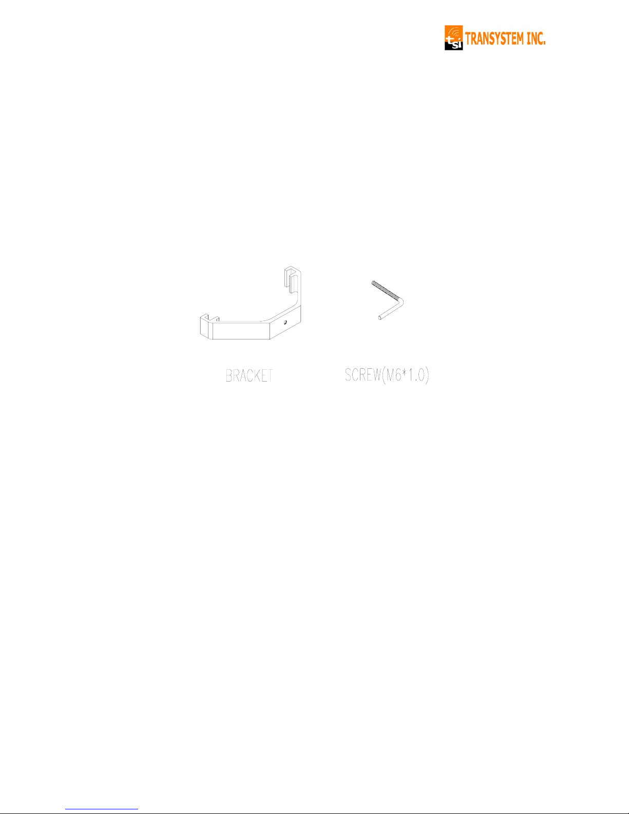
2.1.1 Mounting Bracket Assembly Suite
The following accessories are suggested for mounting the transmitter to
the pole. A set of mounting bracket and one L type screw. Please contact
TSI sales department for this accessory.
4
Page 5
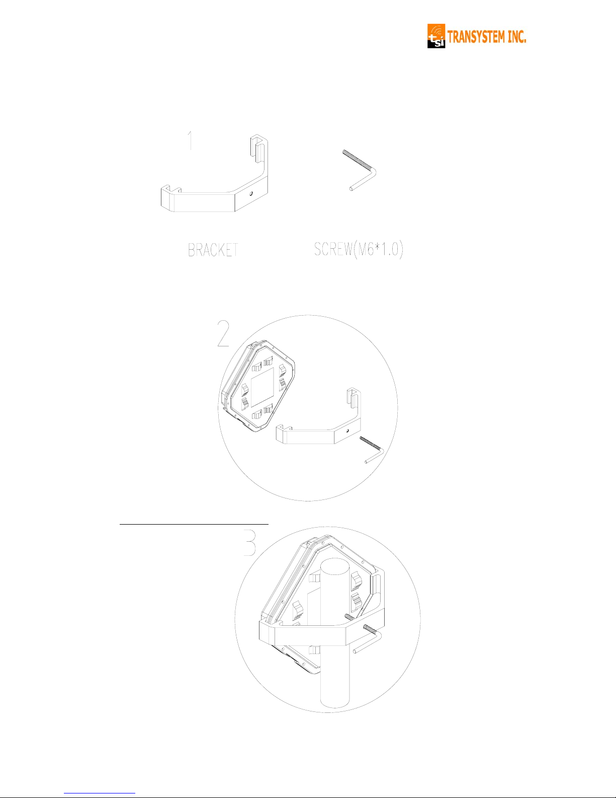
2.1.2 Step by Step Installation
Step 1 – Attach sequence
Left to right: Bracket, Mounting screw.
Step 2 – How to Attach
The concave of Bracket 2 is for holding onto the pole.
Step 3 – Tighten the bracket
5
Page 6
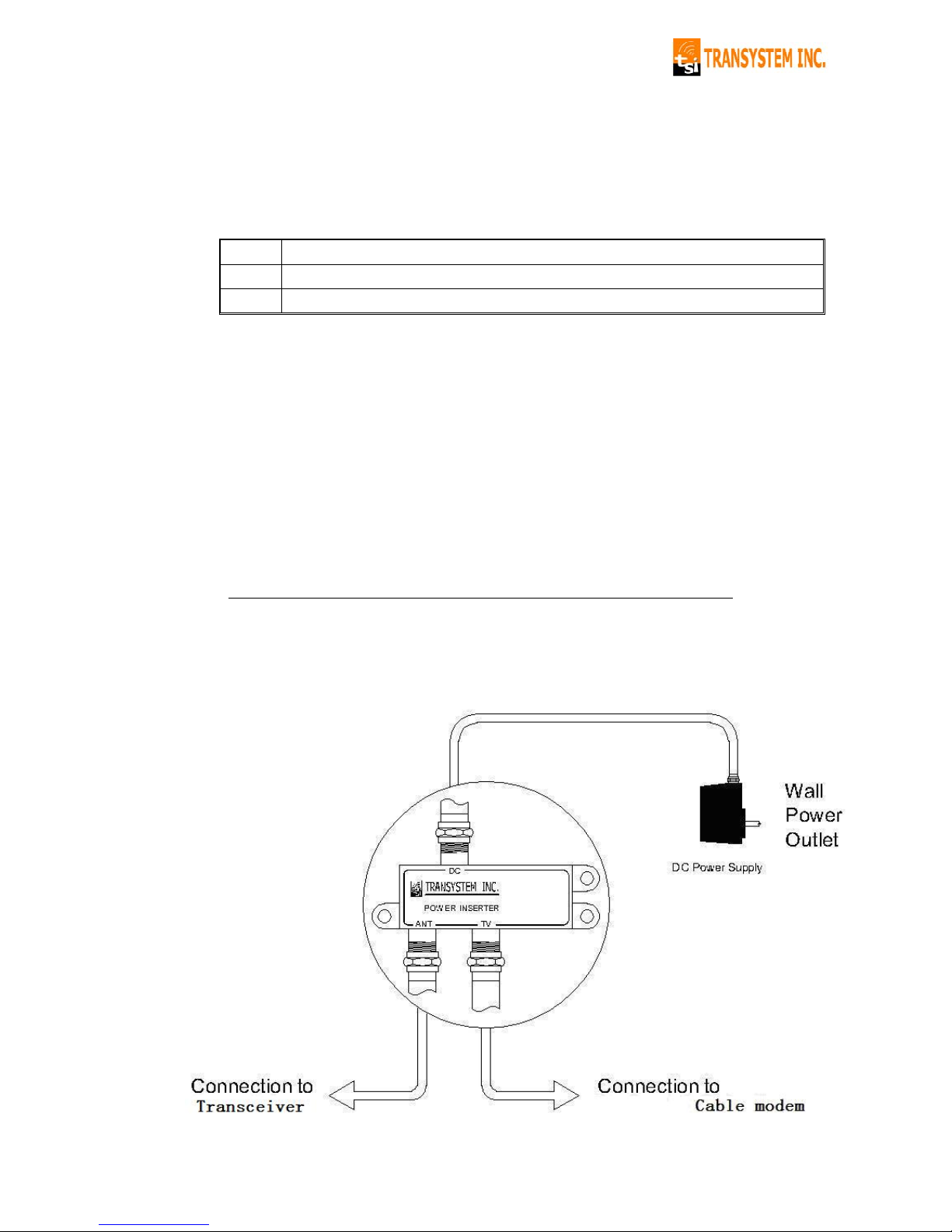
2.2 Connection to the Power Inserter and Cable Modem
Connections to the transmitter are shown in diagram 2.2. Please note:
① The power inserter normally has 3 ports:
DC Connect to wall adapter with RG-59 cable
ANT Connect to the Transmitter
TV Connect to Cable modem
VERY IMPORT ANT NOTICE!
a. The power inserter should be correctly connected, or the transmitter
will not operate.
b. Ensure that all wires and cables are hooked up before plugging into
the AC adapter/power supply (i.e. you must hook up the power supply
last).
② After connection, the F connector of the transmitter must be sealed with
an asphalt sealing tape. (For details, please refer to Section 2.3
Waterproofing Connections)
Diagram 2.2: Connection to Cable modem & Power Inserter
6
Page 7
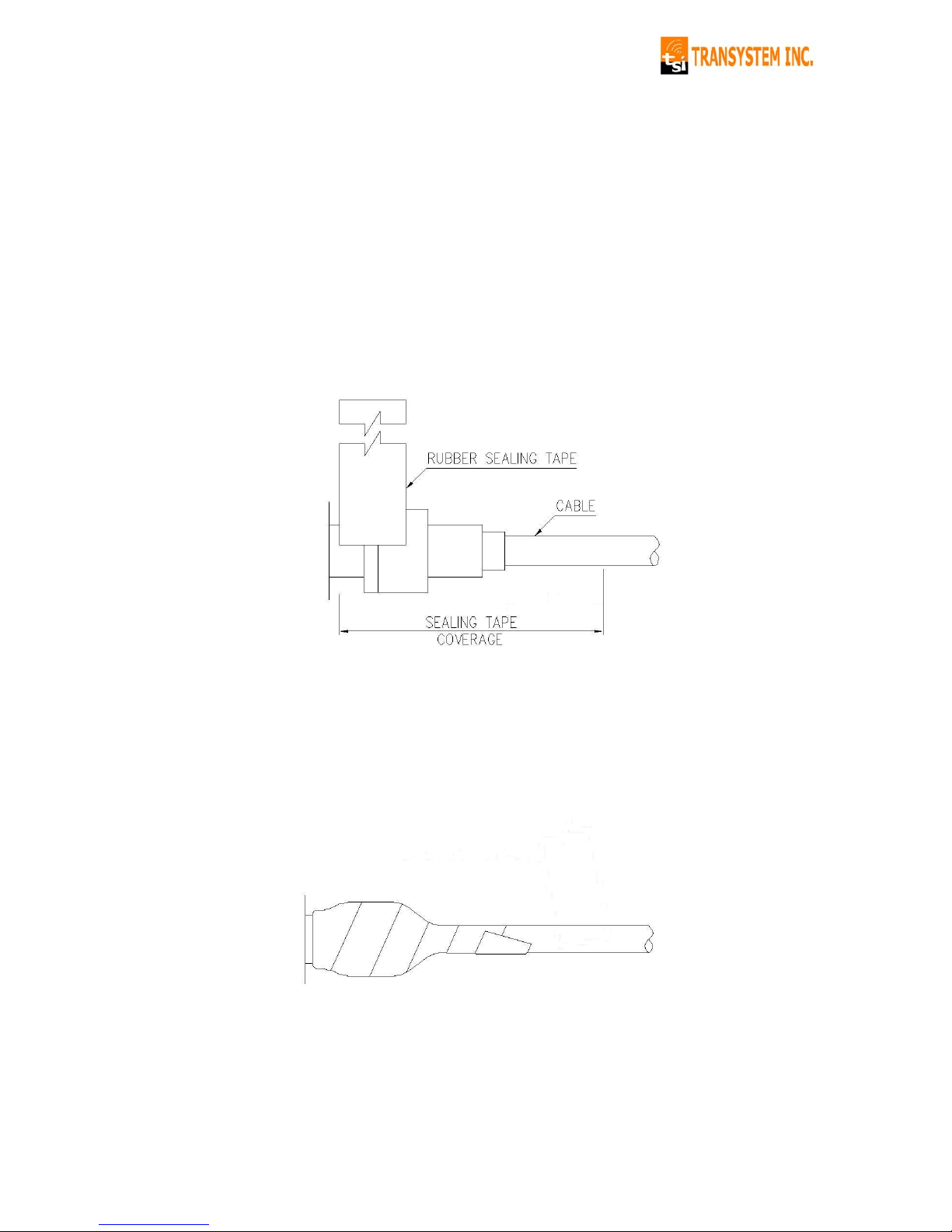
2.3 W aterpr oofin g Connections
Water-proofing is very important during installation of the transmitter.
Please use the included water-proof asphalt tape to seal off the
F-connector as shown below:
① After you plug in the coaxial cable into the F-connector, use the included
water-proofing asphalt tape to seal off the F-connector from the bottom (i.e.
the part close to Transceiver). Note that the tape must wrap up all the thread
of the F-connector.
② The wrap up of the tape must be tight and sturdy. Each wrap-around must
cover at least 50% width of the previous wrap-around.
7
Page 8
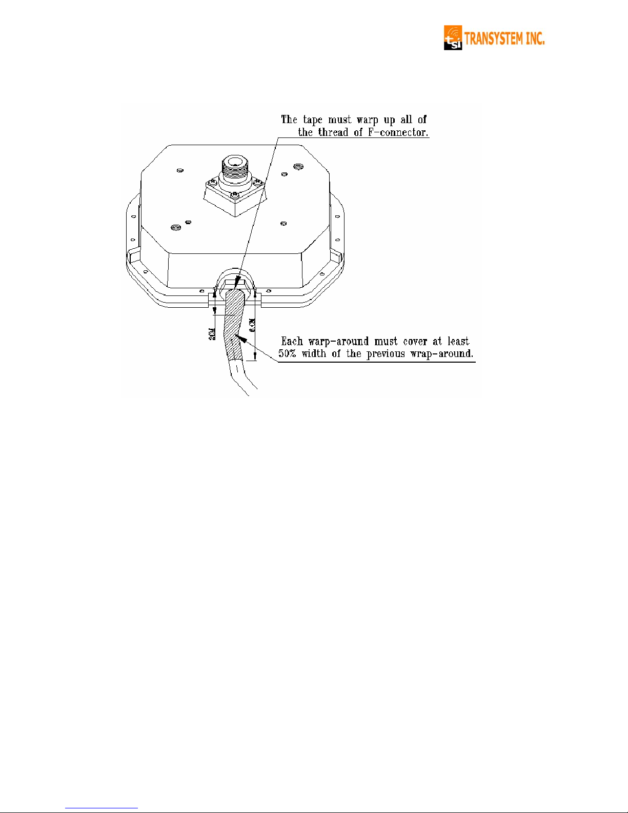
③ The total width of the wrap-around is about 6cm, which corresponds to 7
to 8 rounds of tapes.
* Warning: If you do not follow the above procedure, the transmitter could
become malfunctioning due to water leakage.
8
Page 9
Chapter 3 Accessories
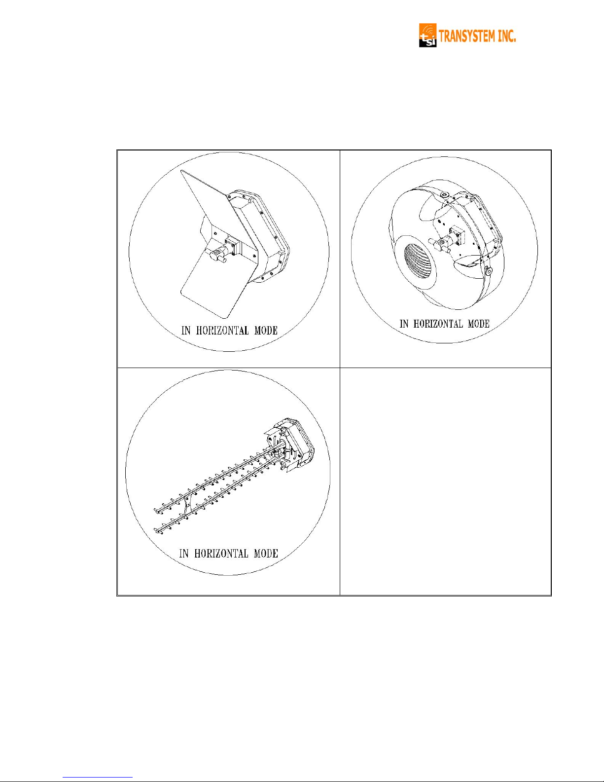
3.1 MMDS Antenna
TSI is proud to offer a complete line of 2.5GHz antennas specifically
designed to satisfy your subscribers. Below are the series:
12dBi Corner Reflector 15dBi Spotbeam
17 dBi Viper
9
 Loading...