

TransWorld Antennas TW8080 Instruction Manual
TW8080
™
The Adventurer Monobander™
TransWorld Antennas
INSTRUCTION MANUAL

TransWorld Antennas
TW8080TM
TW8080TM Instruction Manual
1
Contents
1 Limited Warranty 2
2 Important Safety Information 3
3 Specifications
3.1 Mechanical 4
3.2 Electrical 4
3.3 VSWR Performance 5
4 Unpacking 6
5 The Components of your Antenna 7
6 Getting started
6.1 Tools needed 8
6.2 Antenna Setup 8
6.3 Connections 11
6.4 Tuning 11
7 Schematics 15
8 Contact Information 16
Due to continual product improvements, the information in this manual is subject
to change any time without notice. TransWorld Antennas will be held free from
liability, any problems arising from the use of this manual or the products
described herein.
Manual Rev V1.1

TransWorld Antennas
TW8080TM
2 TW8080TM Instruction Manual
1 Limited Warranty
TransWorld Antennas warrants to the original owner of this product if purchased from an
authorized dealer or directly from TransWorld Antennas to be free from defects in
material and workmanship for a period of 12 months from date of purchase, provided
dated proof of purchase.
TransWorld Antennas agrees to repair or replace, at TransWorld Antennas’ option, any
defective product still under warranty. TransWorld Antennas will cover return shipping
only. The warranty becomes null and void if it is determined that the product was subject
to conditions beyond what the product is rated for, including, but not limited to, over
power limits, extreme environmental conditions such as flood or fire, or general misuse.
TransWorld Antennas will repair or replace, at TransWorld Antennas’ discretion, any outof-warranty TransWorld Antennas product provided all part, labor, or other repair costs
are provided by the customer, the amount of which is determined by TransWorld
Antennas.
All repairs, in warranty and out-of-warranty should be sent to TransWorld Antennas along
with a brief description of the problem and the circumstances, environmental conditions,
and equipment used at the time the problem occurred. For warranty product repairs, a
dated proof of purchase must also be supplied.
TransWorld Antennas will not be held liable, under any circumstances, for damages
resulting from the use of any TransWorld Antennas product.
TransWorld Antennas reserves the right to make changes to this product, in part or in
whole, at any time, in form, function, or manufacture, without obligation to install or incur
any costs relating to the installation of modified parts onto existing product.
This warranty gives you specific rights. Other rights may apply, which vary from state to
state.
An optional extended limited warranty purchased from TransWorld Antennas extends the
period of this warranty to 24 months or 36 months, depending on warranty product
purchased.

TransWorld Antennas
TW8080TM
TW8080TM Instruction Manual
3
2 Important Safety Information
THE INSTALLATION OF THIS PRODUCT NEAR POWER
LINES IS DANGEROUS. FOLLOW THE ENCLOSED
DIRECTIONS.
1. If you are installing an antenna for the first time, for your own safety, seek
PROFESSIONAL ASSISTANCE. Your dealer can explain which mounting
method to use for the size and type antenna you are about to install.
2. Select your installation site with safety; the distance from power lines should be
at least twice the height of the antenna and mast combined. REMEMBER:
ELECTRIC POWER LINES AND PHONE LINES LOOK ALIKE. FOR YOUR
SAFETY, ASSUME THAT ANY OVERHEAD LINES CAN KILL YOU. When
installing your antenna, REMEMBER:
a. DO NOT use a metal ladder.
b. DO NOT work on a wet or windy day.
c. DO dress properly (shoes with rubber soles and heels, rubber gloves,
long sleeve shirt or jacket).
3. If the assembly starts to drop, get away and let it fall. Remember, the antenna,
the mast, the cable and the metal wires are all excellent conductors of electrical
current. Even the slightest touch of any of these parts to a power line completes
an electrical path through the antenna and the installer.
4. If any part of the antenna system should come in contact with a power line,
DON’T TOUCH IT OR TRY TO REMOVE IT YOURSELF. CALL YOUR LOCAL
POWER COMPANY. They will remove it safely.
GENERAL INSTALLATION INSTRUCTIONS FOR MAST MOUNTED ANTENNAS
1. Carefully follow the mounting instructions of the product.
2. Connect your mast at Ground by using a copper wire of minimum section 6 mm2.
3. Pay attention to the correct locking of nuts and screws.
4. If necessary (windy areas or very long masts) the use of special anti-wind rods is
recommended.
5. While your antenna is on Tx mode (transmitting) DO NOT stand nearby.
6. It is recommended to strictly respect the maximum power settled by law and
follow the instructions manual of the product.
7. Stick self-adhering “DANGER” label at eye level on your mast.
TransWorld Antennas
TW8080TM
4 TW8080TM Instruction Manual
3 Specifications
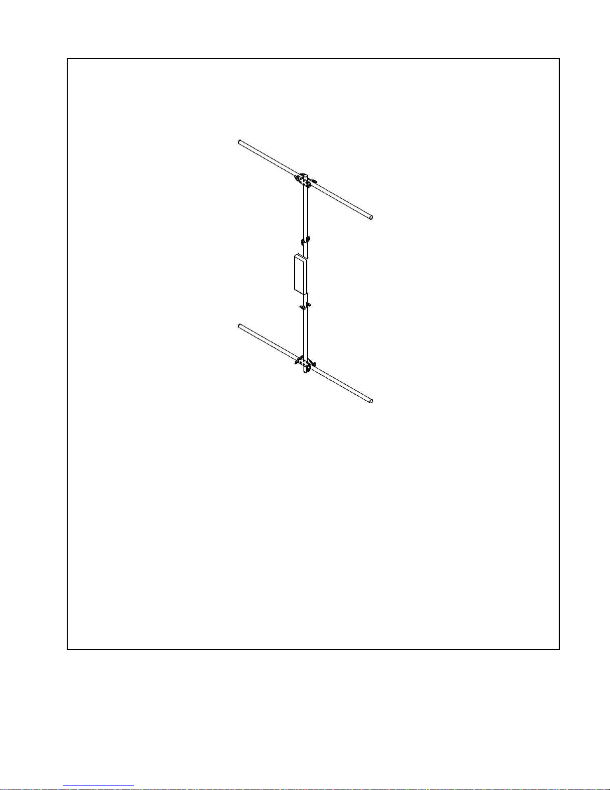
Congratulations on the purchase of your TW8080 antenna! The TW8080
represents a revolutionary jump in HF antenna performance, convenience, and
reliability. The ruggedly built TW8080 was designed with ease of use in mind.
Therefore, all TW8080 antennas are pre-assembled and tuned at the time of
manufacture. With its compact three-part fold-up design, the TW8080 is ready to
go right out of the box1 for permanent or temporary installation using the supplied
quick break-down stand.
The TW8080 is a center fed vertical dipole antenna with a very low radiation
take-off angle (around 27 degrees above horizontal), allowing for very long skips
using low power on 80 meters. The TW8080 is a ground-mounted omnidirectional antenna, requiring no ground radials, tower, or rotor.
3.1 Mechanical
Dimensions (folded):
Three pieces, each less than 34" long
Antenna Dimensions (after setup):
Width: 5' 3-1/2"
Height: 6' 10-1/2"
8' 3" on permanent mounting tube
Weight: Approx. 13 lbs
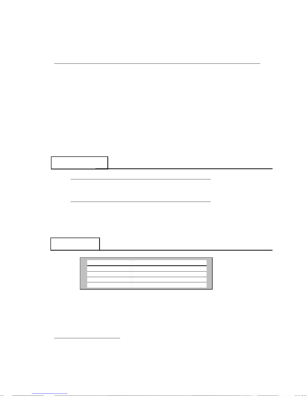
3.2 Electrical
Mode
Maximum Power
SSB 1,200W PEP
CW 800W
RTTY 500W
AM 375W, 100% mod (full legal)
1
Tuning may be required.
TransWorld Antennas
TW8080TM
TW8080TM Instruction Manual
5
3 Specifications
(cont.)
Antenna (cont.)
Band
2 : 1 Band Width
2
Typical minimum VSWR
80m 50 kHz 1.1 : 1
Directionality: Omni directional
Vertical radiation angle: 27°
Band selection: monoband only
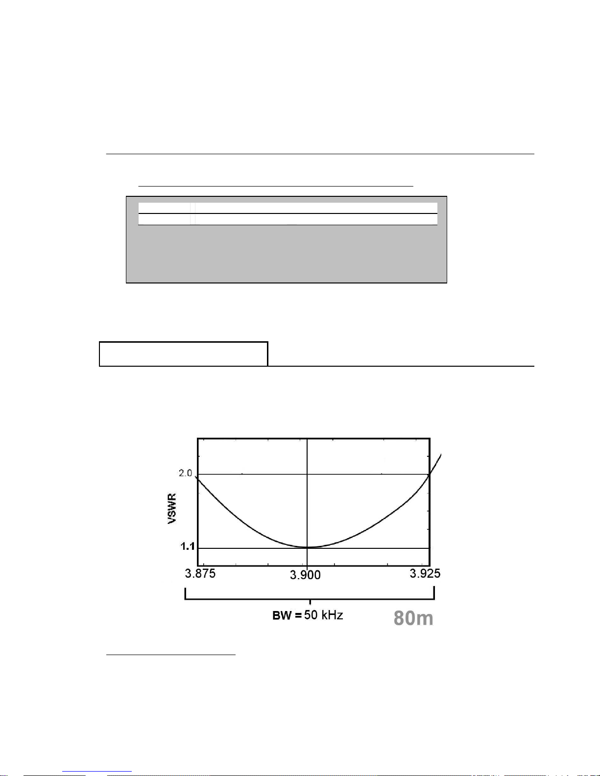
3.3 VSWR Performance
The plot below represents the VSWR performance of the antenna under the test
circumstances noted at the bottom of this page. The term “bandwidth” here refers
to the range of frequencies over which the antenna exhibits a VSWR of 2:1 or
less.
2
Test conditions: 100 feet of quality RG8/U coax, 100W output power, antenna mounted approx. 24” above ground with
no external objects, metallic or otherwise, within 20ft radius of the antenna.
 Loading...