

Page 1

™
TW2010
™
The Adventurer
Trans World Antennas
INSTRUCTION MANUAL
Page 2

Trans World Antennas
Danger: Do not install this antenna where there
exists the possibility of contact with power lines. Even
with painted or coated antennas, the risk of electrical
shock exists, which could cause serious injury or
death.
TM
TW2010
Due to continual product improvements, the information in this manual is subject
to change any time without notice. Trans World Antennas will be held free from
liability, any problems arising from the use of this manual or the products
described herein.
Manual Rev V1.2
TW2010TM Instruction Manual 1
Page 3

Trans World Antennas
Contents
1 Limited Warranty 3
2 Specifications
2.1 Mechanical 4
2.2 Electrical 4
2.3 VSWR Performance 6
3 Unpacking 7
4 The Components of your Antenna
4.1 The Structure 8
4.2 The Controller 9
4.3 Cabling 11
TM
TW2010
5 Getting started
5.1 Tools needed 12
5.2 Antenna Setup 12
5.3 Connections 15
5.4 Controller operation 22
5.5 Tuning 23
5.6 Fuse replacement 27
6 Schematics 29
7 Accessories 31
8 Contact Information 32
2 TW2010TM Instruction Manual
Page 4

Trans World Antennas
1 Limited Warranty
Trans World Antennas warrants to the original owner of this product if purchased from an
authorized dealer or directly from Trans World Antennas to be free from defects in
material and workmanship for a period of 12 months from date of purchase, provided
dated proof of purchase.
Trans World Antennas agrees to repair or replace, at Trans World Antennas’ option, any
defective product still under warranty. Trans World Antennas will cover return shipping
only. The warranty becomes null and void if it is determined that the product was subject
to conditions beyond what the product is rated for, including, but not limited to, over
power limits, extreme environmental conditions such as flood or fire, or general misuse.
Trans World Antennas will repair or replace, at Trans World Antennas’ discretion, any
out-of-warranty Trans World Antennas product provided all part, labor, or other repair
costs are provided by the customer, the amount of which is determined by Trans World
Antennas.
TM
TW2010
All repairs, in warranty and out-of-warranty should be sent to Trans World Antennas
along with a brief description of the problem and the circumstances, environmental
conditions, and equipment used at the time the problem occurred. For warranty product
repairs, a dated proof of purchase must also be supplied.
Trans World Antennas will not be held liable, under any circumstances, for damages
resulting from the use of any Trans World Antennas product.
Trans World Antennas reserves the right to make changes to this product, in part or in
whole, at any time, in form, function, or manufacture, without obligation to install or incur
any costs relating to the installation of modified parts onto existing product.
This warranty gives you specific rights. Other rights may apply, which vary from state to
state.
An optional extended limited warranty purchased from Trans World Antennas extends the
period of this warranty to 24 months or 36 months, depending on warranty product
purchased.
TW2010TM Instruction Manual 3
Page 5

Trans World Antennas
TW2010
2 Specifications
Congratulations on the purchase of your TW2010 antenna! The TW2010
represents a revolutionary jump in HF antenna performance, convenience, and
reliability. The ruggedly built TW2010 was designed with ease of use in mind.
Therefore, all TW2010 antennas are pre-assembled and tuned at the time of
manufacture. With its compact three-part fold-up design, the TW2010 is ready to
go right out of the box1 for permanent installation, or quick and easy travel, using
the optional Quadrapod folding travel stand.
The TW2010 is a center fed vertical dipole antenna with a very low radiation
take-off angle (around 27 degrees above horizontal), allowing for very long skips
using low power on 10, 12, 15 17, and 20 meters2. The TW2010 is a groundmounted omni directional antenna, requiring no ground radials, tower, or rotor.
2.1 Mechanical
TM
Dimensions (folded3):
Three pieces, each less than 34" long
Antenna Dimensions (after setup):
Width: 5' 3-1/2"
Height: 6' 10-1/2"
8' 3" on permanent mounting tube
Weight: Approx. 10 lbs
2.2 Electrical
Controller
Function: 5-band switching, auto or manual
Power Requirements: 12VDC, 200mA
Antenna
Mode Maximum Power
SSB 1,200W PEP
CW 800W
RTTY 500W
AM 375W, 100% mod (full legal)
1
Tuning may be required
2 Though some have reported some results on 2m, 6m, and 70cm, only 10-, 12-, 15-, 17-, and 20- meters are officially
supported by Trans World Antennas.
3
Not including optional folding stand
4 TW2010TM Instruction Manual
Page 6

Trans World Antennas
TM
TW2010
2 Specifications
Antenna (cont.)
Band 1.5 : 1 Band Width
10m 1,210 kHz 1.1 : 1
12m <Entire Band> 1.1 : 1
15m <Entire Band> 1.1 : 1
17m <Entire Band> 1.1 : 1
20m 200 kHz 1.1 : 1
Directionality: Omni directional
Vertical radiation angle: 27°
Band selection: 5-band relay switched via included controller
(cont.)
4
Typical minimum VSWR
4
Test conditions: 100 feet of quality RG8/U coax, 100W output power, antenna mounted approx. 32” above ground with
no external objects, metallic or otherwise, within 20ft radius of the antenna.
TW2010TM Instruction Manual 5
Page 7

Trans World Antennas
TW2010
2.3 VSWR Performance
The five plots below represent the VSWR performance of the antenna under the
test circumstances noted on page 5. The term “bandwidth” here refers to the
range of frequencies over which the antenna exhibits a VSWR of 1.5:1 or less.
TM
6 TW2010TM Instruction Manual
Page 8

Trans World Antennas
3 Unpacking
TM
TW2010
Here’s what you should find in your shipping box:
• Corrugated drawer containing the four main pieces of the antenna
structure:
o Top section
o Middle section
o Bottom section
o Permanent mounting assembly
• An inner shipping carton:
o This manual
o 65-1/2 foot quick disconnect control cable
o Antenna auto controller
o Power cable for controller
Save all packaging materials! The original shipping materials may serve as a
very handy travel box for portable applications. Also, if the antenna is returned
for warranty or money-back guarantee claims, all original packaging materials will
be required for approved shipping.
TW2010TM Instruction Manual 7
Page 9

Trans World Antennas
TW2010
4 The Components of your Antenna
There are three basic components to your new TW2010: The structure,
the controller, and cabling.
4.1 The Structure
The structure of your antenna has been built in four pieces, top,
middle, bottom, and permanent mounting assembly. The top and
bottom pieces fold up for quick and easy travel. Fold-up and
assembly of the three main structure pieces is achieved using preinstalled clamp knobs. See below for a summary of these four
components.
TM
Top Section
32.2” x 6.25” x 3.8”
Middle Section
30.13” x 7.41” x 4.88”
Bottom Section
33.75” x 6.25” x 3.8”
Permanent Mounting
Assembly
48.00” x 3.20” x 1.25”
8 TW2010TM Instruction Manual
Page 10

Trans World Antennas
4.2 The Controller
Your TW2010 is supplied with a 5-band auto controller used for
band switching. The controller can be used in automatic mode or
manual mode. Automatic mode is available for use with many
modern Icom and Yaesu radios, using an optional cable,
available from Trans World Antennas.
Below are diagrams of the front and rear panels with feature
descriptions.
Front Panel
TM
TW2010
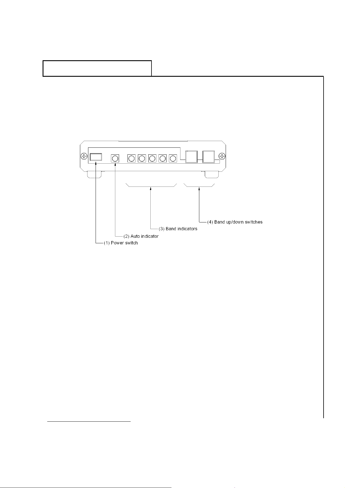
(1) Power switch. Use to turn your controller on and off.
(2) Auto indicator. This amber LED will light when the controller is in automatic
mode. This LED will blink when, in automatic mode for Icom transceivers, an
attempt is made to operate the antenna outside the 10m to 20m range.
(3) Band indicators. These five green LEDs are used to display which band the
antenna is currently switched to (assumes the antenna is properly connected to
the controller).
TW2010TM Instruction Manual 9
Page 11
Trans World Antennas
(4) Band up/down switches. By pressing Band Up or Band Down, the
controller will go into manual mode and the auto indicator will go dark. Press
Band Up or Band Down to cycle up or down through the five bands, respectively.
By pressing both Band Up and Band Down at the same time, the controller will
initiate automatic mode and the Auto indicator will light. See Rig Select Switch
below for more information.
TW2010
Rear Panel
TM
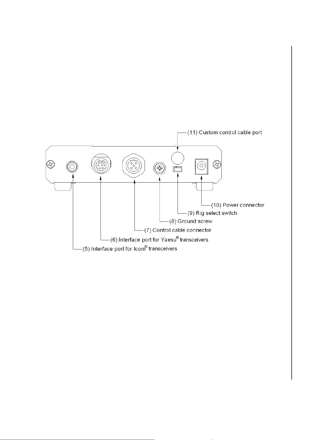
(5) Interface port for Icom transceivers. This port is used to connect the
controller to a compatible Icom transceiver to allow the controller to successfully
operate in automatic mode. The controller will work with most any Icom
transceiver that has a 3.5mm “Remote” jack, and can communicate information
from this port at 9600 bps. This feature requires an optional TW-AC-1-ICOM
cable, available from Trans World Antennas.
(6) Interface port for Yaesu transceivers. This port is used to connect the
controller to a compatible Yaesu transceiver to allow the controller to
successfully operate in automatic mode. The controller will work with any
Yaesu transceiver that has an eight-pin mini-din “CAT/Linear” connector. This
feature requires an optional TW-AC-1-YC cable, available from Trans World
Antennas.
(7) Control cable connector. This port is used to connect the supplied quickdisconnect control cable. See “(11) Custom control cable port” below for more
information regarding homemade control cables.
10 TW2010TM Instruction Manual
Page 12
Trans World Antennas
(8) Ground screw. Although not required, it is recommended to ground your
controller as you would other pieces of equipment in your shack. Use this
supplied screw for grounding purposes.
TW2010
TM
(9) Rig Select switch. For automatic mode only, this switch selects which
transceiver type to use. Switch to “I” for Icom
transceivers.
(10) Power connector. This power connector uses a 2.5mm power cable
(supplied) to connect the controller to 12VDC. The controller should pull no more
than 200mA. Center pin is positive.
(11) Custom control cable port. To use a control cable other than the cable
supplied with the antenna, this hole is provided to internally wire your custom
cable. The unit ships with a black plastic hole plug, which can be easily removed
from the inside of the unit. See page 16 for more information.
transceivers, and “Y” for Yaesu
4.3 Cabling
Control cable. The TW2010 is supplied with a 65-1/2 foot long black PVC
jacketed 5-conductor control cable with 12mm metal screw-on connector ends for
quick connection to the controller and antenna. This cable connects to the
“Control Cable” connector on the back of the controller, and the identical
connector on the back of the antenna structure’s switching network box (see
figure on page 15). Without this cable, the antenna will operate in 20m mode
only.
Power cord. A six-foot 2-conductor power cord is supplied with your TW2010
for powering the controller. This cord should be connected to a 12 to 18VDC
power supply. The cord’s two conductors are black and black with a white stripe.
The black-with-white-stripe conductor connects to the positive terminal of your
power supply, and the solid black conductor connects to the negative terminal
(see figure on page 15). An internal rectifier diode will protect the controller if it is
accidentally connected in reverse.
TW2010TM Instruction Manual 11
Page 13
TM
Trans World Antennas
TW2010
5 Getting Started
Getting started with your new TW2010 is quick and easy. Follow these steps to
get started using your new antenna right away.
5.1 Tools Needed
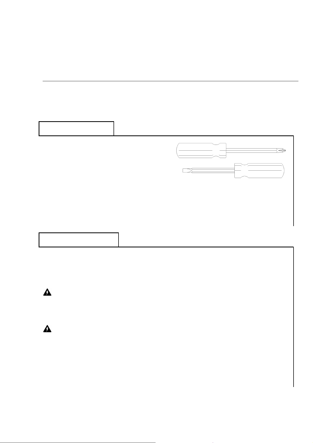
Only two tools should ever be needed for use
with your TW2010. First, a small Phillips
screwdriver will be required to open the
switching array box for tuning (page 22), or
for accessing the inside of the controller for
changing the fuse (page 25) and attaching a
custom control cable, if desired (page 16). Second, a small flat head screwdriver will
be required to attach a custom control cable (page 16).
Under normal circumstances, after initial tuning, no tools should ever be required for
break down, transport, and setup of the TW2010.
5.2 Antenna Setup
1) Choose a location for your antenna. The area you choose for your antenna
should be at least 10 meters (about 33 feet) from any metal structure or other
objects that could detune the antenna.
Danger: The antenna should not be placed anywhere near power lines, as
serious injury or death could occur. And as always, CALL BEFORE YOU DIG to
ensure you know where buried gas, water, sewer, power, and other service lines
are located.
Danger: As with any antenna installation, exposure limits should be
calculated to ensure safe operation. Vertical dipoles, such as the TW2010,
should not be operated at more than about 200W on 20m. Visit the ARRL
website (http://www.arrl.org/news/rfsafety/) for more information on exposure
limits and calculations.
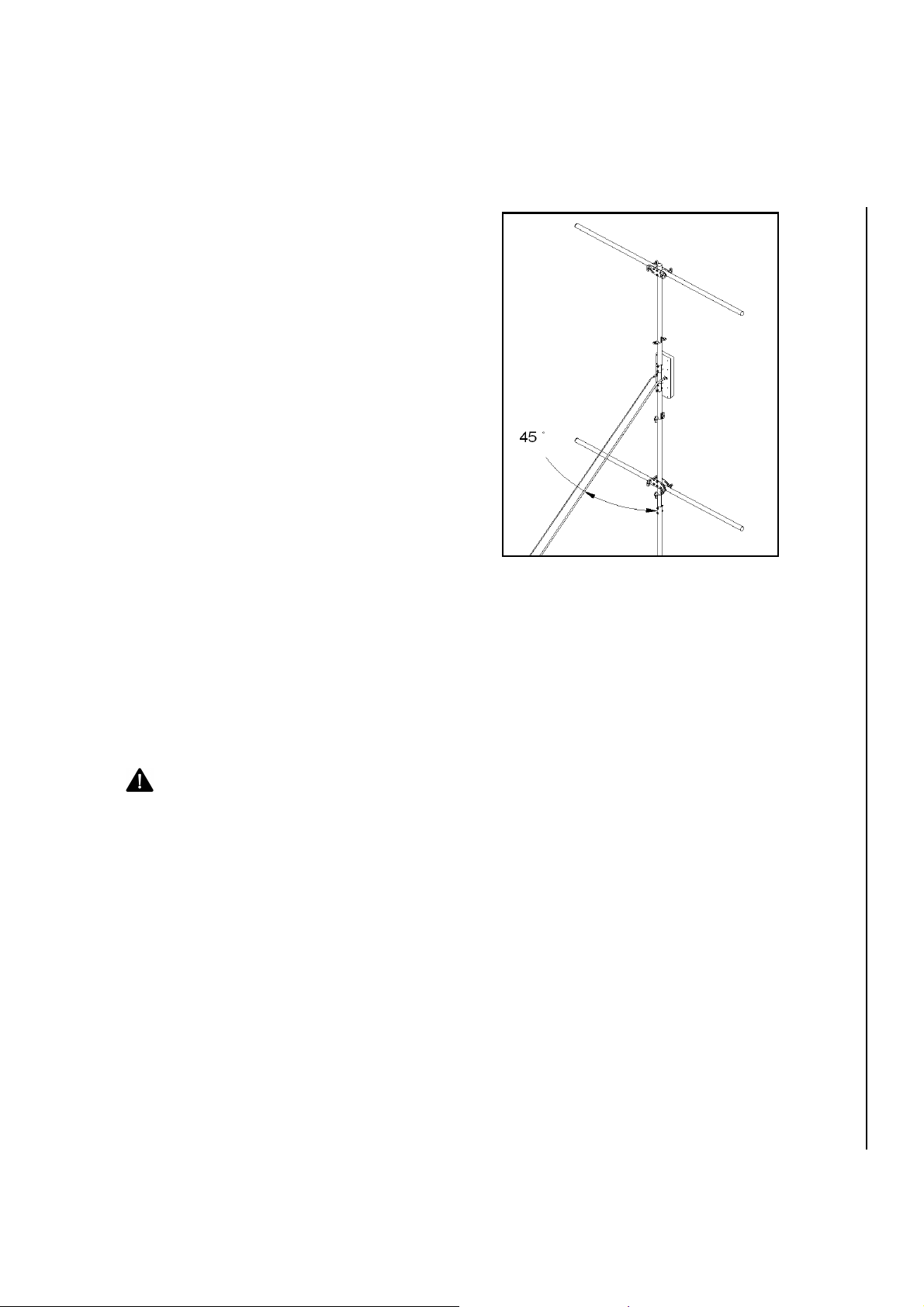
The antenna’s coax feed line and control cable should be run at a 45-degree
angle down from the structure to the ground to minimize parasitic coupling (see
12 TW2010TM Instruction Manual
Page 14
Trans World Antennas
figure on page 16). Failure to do so will result in higher than expected VSWR
readings. Plan for this extra footprint when choosing a location for your antenna.
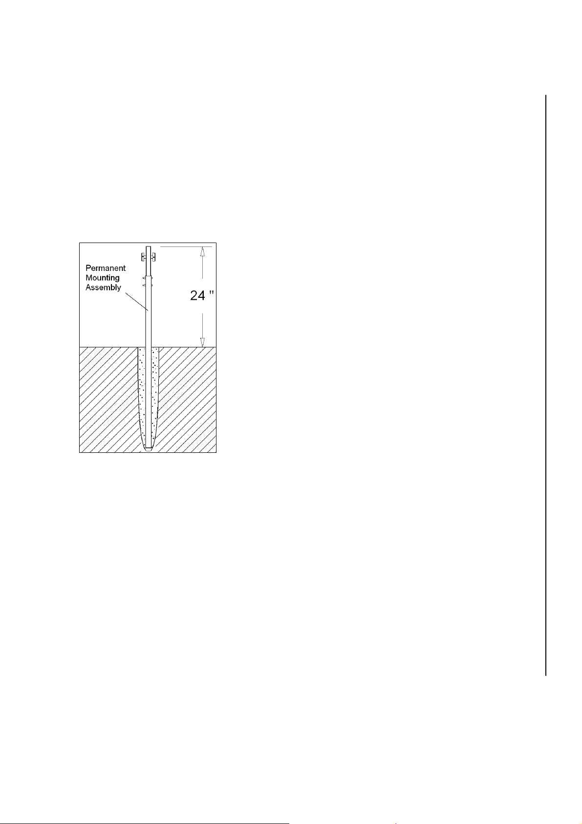
2) Install Permanent Mounting Assembly. The supplied Permanent Mounting
Assembly consists of insulator rod attached to an aluminum tube using stainless
steel hardware. The assembly can be installed with or without the use of
concrete. Though concrete will provide a more secure, permanent base for your
antenna, it will be difficult to remove or re-position later. The assembly should be
inserted about 12-24” into the ground, exposing 24-36” of the assembly above
ground.
It is suggested that the antenna be tried in an area
using the permanent mounting assembly in a hole in
the ground before concreting, in case the antenna
needs to be moved later. Once you are sure of the
location for the antenna, the Permanent Mounting
Assembly can be concreted into place, if desired.
TW2010
TM
Warning: The fiberglass insulating rod is not
hammer-proof. Do not pound the Permanent
Mounting Assembly into the ground like a stake.
Permanent damage to the fiberglass insulating rod
could occur. If it is necessary to drive the assembly
into the ground, first remove the fiberglass insulating
rod using a 5/16” Allen wrench and a 7/16” socket.
Drive the aluminum permanent mounting tube into
the ground using a rubber mallet. Alternatively, a
conventional hammer can be used if a wooden board is laid over the aluminum
mounting tube before striking.
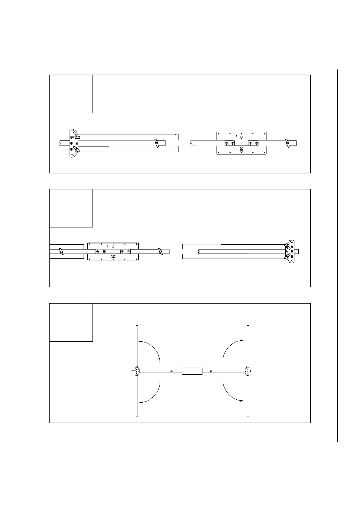
3) Assemble antenna. First, attach the bottom section to the middle section,
making sure to slide the pieces completely together. The ¼” slots on the end of
the middle section should engage completely with the stud of the clamp knob on
the end of the bottom section, as shown in step 1 below. Tighten the clamp knob
snugly.
Second, attach the middle section to the top section as shown in step 2 below.
Again, the clamp knob stud should fully engage with the slots on the end of the
top section. Tighten the clamp knob snugly.
Finally, fold the arms of the top and bottom sections out as shown in step 3. The
arms should be folded out completely horizontal. Firmly tighten all four clamp
knobs to ensure that the top arms do not rotate downward over time.
TW2010TM Instruction Manual 13
Page 15
Trans World Antennas
3
Attach the bottom section to the middle section, making sure to
slide the pieces completely together and tighten clamp knob.
1
Attach the middle section to the top section and tighten clamp
knob.
TM
TW2010
2
Loosen arm clamp knobs. Fold out arms on top and bottom
sections, then re-tighten arm clamp knobs.
14 TW2010TM Instruction Manual
Page 16
Trans World Antennas
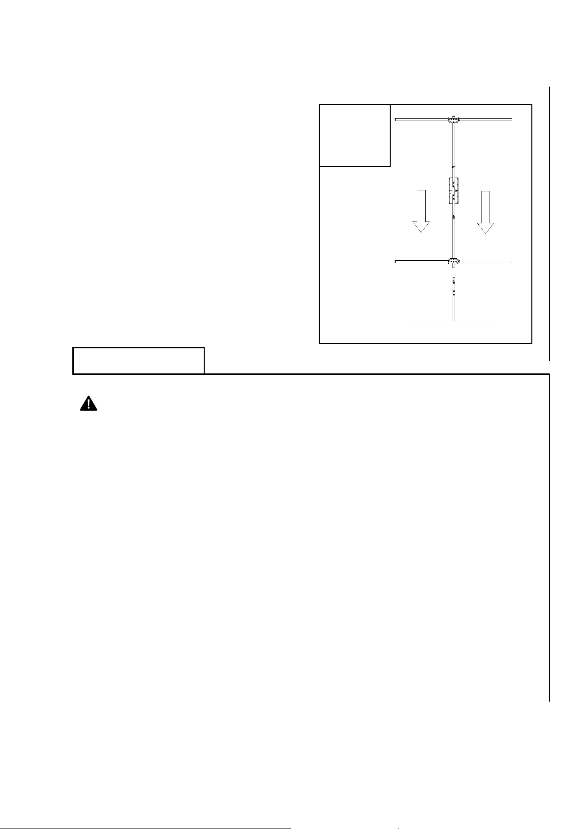
4) Install antenna onto the Permanent
Mounting Assembly. As shown at right,
slide the bottom of the bottom section onto
the Permanent Mounting Assembly’s
insulator rod. As with assembly above, the
slots on the end of the bottom section
should fully engage with the mounting
assembly’s clamp knob stud. Firmly tighten
the clamp knob.
TM
TW2010
4
5.3 Connections
Warning: Turn off equipment before making or removing any connections.
Failure to do so could result in equipment damage.
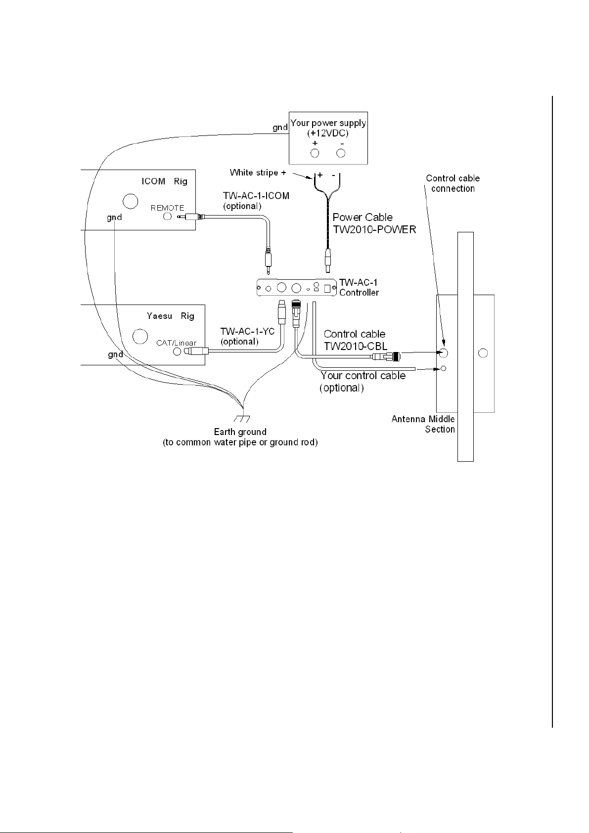
See the figure on page 15 for connection details.
Ground connection. For reduced noise and RF exposure in your shack, all
equipment should be grounded to one common point on a water pipe or a ground
rod driven into the earth. The TW2010’s controller has a #6 ground screw
installed on the back for this purpose, labeled “gnd.”
Accessory cables. The cables labeled TW-AC-1-ICOM and TW-AC-1-YC are
optional accessories available from Trans World Antennas. These cables
interface the controller to a compatible Icom or Yaesu transceiver,
respectively, and are required to operate your controller in automatic mode.
Power cable. The power cable (TW2010-POWER) is two-conductor cable with
a 2.5mm DC power connector installed on one end and stripped and tinned
conductors on the other end. This cable must be wired into a +12-18V DC power
supply with 200mA of current to spare. One conductor has a dashed white line,
designating the positive side of the connection.
TW2010TM Instruction Manual 15
Page 17
Trans World Antennas
TM
TW2010
Controller connection details
Stock control cable. The 5-conductor control cable that shipped with your
antenna (TW2010-CBL) has screw-lock connectors on each end. These simply
plug into your controller and the antenna’s switching array box. The cable
connectors will attach to the mating connectors in only one orientation. Insert the
cable connector into the mating connectors and screw the metal collar snugly.
Caution: over tightening may lead to difficulty in cable removal later.
Custom control cable. The cable designated “Your control cable” in the figure
above is an alternative way to connect your antenna to its controller. This should
be a 5-conductor cable, not to exceed 0.312” in diameter. The leads of the
individual conductors should be stripped back about ¼”. The overall length of the
cable should not exceed 150 feet, as the losses in the wire will prevent the
antenna’s switching array from operating properly. See page 16 for more
information.
16 TW2010TM Instruction Manual
Page 18
Trans World Antennas
Coax cable. Connect your coax cable to
your radio and to the SO-239 on the
TW2010’s switching array box. It is highly
recommended to use at least 65 feet of
coax on your TW2010. For best
performance, use a high quality RG-8 or
RG-8X coax cable.
Final connection notes: The control and
coax cables should feed the antenna at a
45-degree angle as shown in the figure at
right. Failure to do so will result in
parasitic coupling and cause higher than
normal VSWR readings.
TM
TW2010
Custom control cable. A custom control cable can be used if you wish to use
an existing cable, if the supplied control cable is too short, if you wish to reserve
the supplied cable for travel applications, etc. If you use your own control cable,
it should contain at least five conductors, each at least 24AWG. The cable
should not be more than about 150 feet in length to avoid excessive voltage
drop. The cable must be installed into the switching array box on the antenna
and in the controller using a small flat head screwdriver. The width of the
screwdriver blade must be no more than 1/8”.
Warning: Make sure that the controller power cable is unplugged from the
back of the controller before opening. Failure to do so may lead to damage to
the controller.
TW2010TM Instruction Manual 17
Page 19
Trans World Antennas
TM
TW2010
Install the cable into
the control box
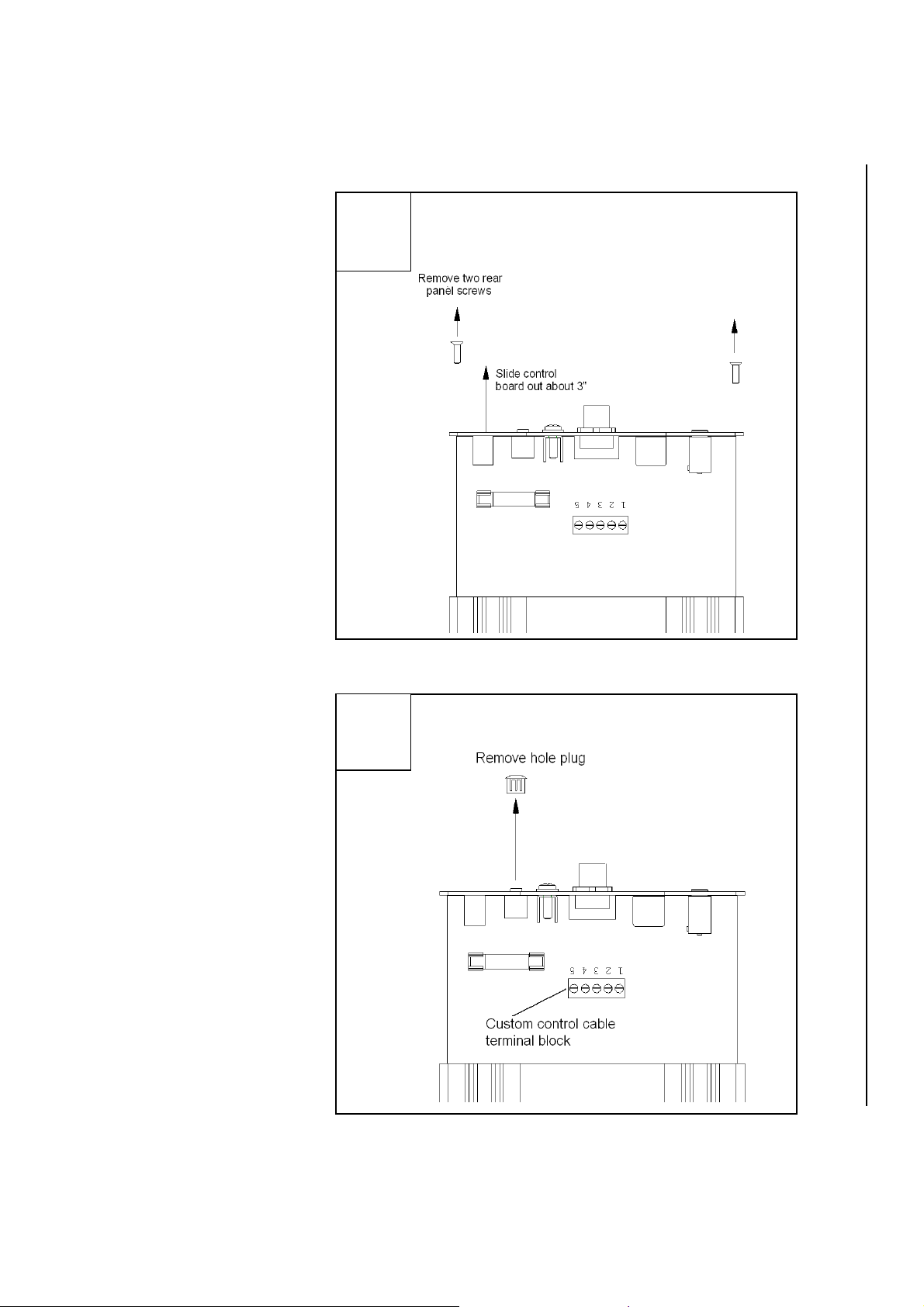
1) Open controller
enclosure. Remove
the two black rear
panel screws from the
controller, as shown in
step 1 at right, and pull
the control board about
3” out of its enclosure.
Remove the controller’s two rear panel
screws and pull board out about 3”.
1
2) Remove hole plug.
Remove the black
plastic hole plug
labeled “Aux” on the
rear controller end
panel, as shown in
step 2. The “Aux” hole
is where your custom
control cable will enter
the controller.
Remove the black plastic hole plug.
2
18 TW2010TM Instruction Manual
Page 20
Trans World Antennas
TM
TW2010
3
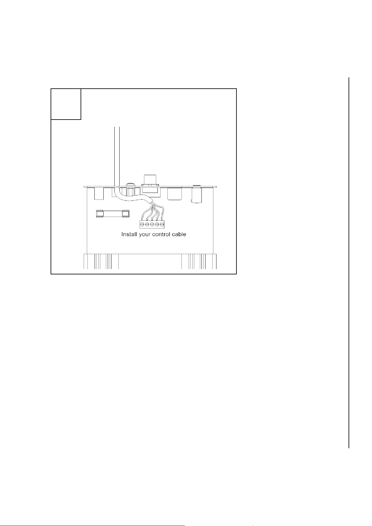
Install your custom control cable in the control
board’s terminal block, making note of which
color of wire is in which numbered terminal
block hole.
3) Connect custom
control cable. Install
your control cable as
shown in step 3 at left.
About 1.5” of outer
jacket of your cable
should be stripped off,
and about ¼” of the
individual conductor
should be stripped
bare. Insert each
conductor into a hole in
the front of the terminal
block, and using your
flat head screwdriver,
tighten the screw in the
top of the terminal
block down snugly.
Give each conductor a
gentle tug after
installation to make
sure it’s in securely.
If your custom control cable has more than five conductors, be sure to snip off
and tape up the excess conductors to avoid a short circuit condition in the
controller later.
Write down which color of wire you insert into which hole (the holes are labeled 1
through 5 on the circuit board). You will need this information when you install
the other end of your control cable into the switching array box on the antenna
structure.
Reinsert the control board back into its enclosure and replace the two end panel
screws.
TW2010TM Instruction Manual 19
Page 21
Trans World Antennas
1
TM
TW2010
Install the cable into the
switching array box
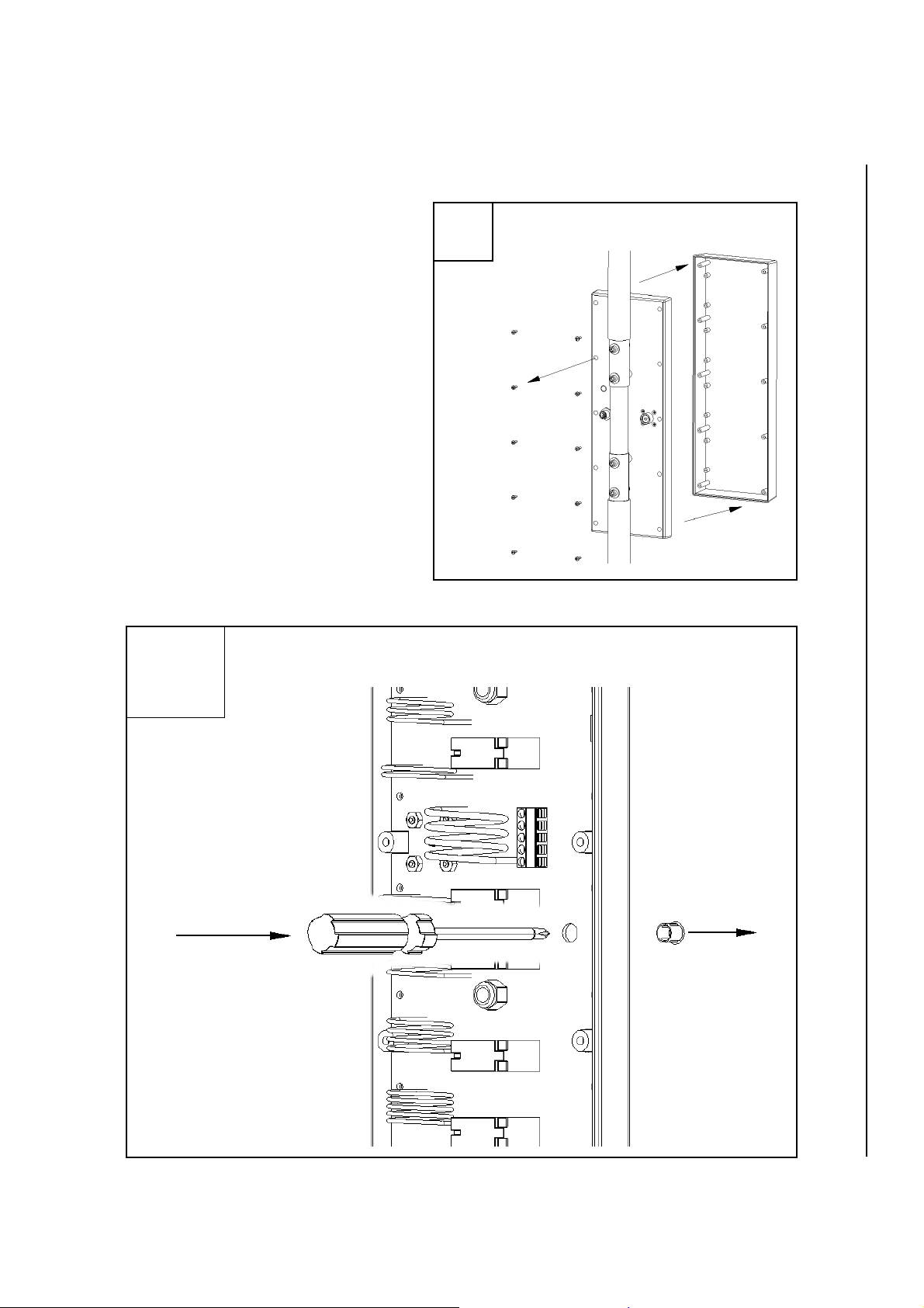
1) Open switching array box.
Remove the ten screws from the
back of the switching array box and
remove the cover. Be careful not
to lose the screws as you remove
them.
2) Remove hole plug. Using a
small screwdriver, pop out the
black plastic hole plug as shown in
step 2 below. Save this hole plug if
you think you will want to remove
your custom control cable later.
The plug will add to the box’s
weather resistance.
Using a screwdriver, pop the plastic hole plug out of the back of
the enclosure
.
2
Remove the ten screws from the back of the
switching array box and remove the cover.
20 TW2010TM Instruction Manual
Page 22
Trans World Antennas
TM
TW2010
3
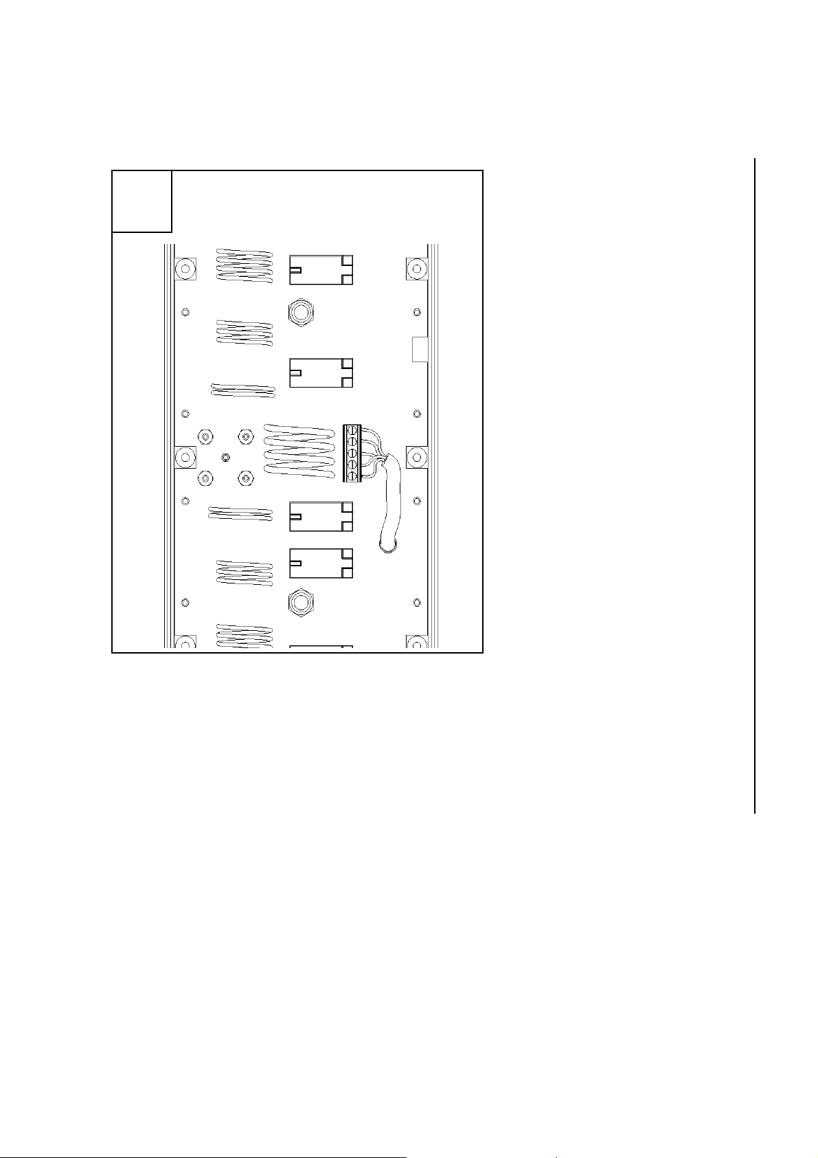
Install your custom control cable in the
board’s terminal block, making sure it is
wired the same as the controller side.
3) Connect control cable.
Next, install your control
cable as shown in step 3 at
left. About 1.5” of outer
jacket of your cable should
be stripped off, and about
¼” of the individual
conductor should be
stripped bare.
Make sure the color /
number combination you
use is the same as that
which you used for the
controller.
Insert each conductor into a
hole in the front of the
terminal block, and using
your flat head screwdriver,
tighten the screw in the top
of the terminal block down
snugly. Give each
conductor a gentle tug after
installation to make sure it’s
in securely.
If your custom control cable has more than five conductors, be sure to snip off
and tape up the excess conductors to avoid a short circuit condition.
Place the cover back on the switching array and replace the ten screws. Make
sure the screws are tight enough to hold the cover securely on, but be careful not
to over-tighten, as the screw holes could strip out.
TW2010TM Instruction Manual 21
Page 23
Trans World Antennas
TW2010
5.4 Controller Operation
The controller provided with the TW2010 allows for quick and easy band
changes. The TW2010 controller can be operated in manual mode or automatic
mode5.
Power. Depress the red power switch on the front of the controller. On powerup, the green 10m LED on the face of the controller should light.
TM
Automatic mode. The amber LED labeled “A” indicates automatic mode when
lit. To activate automatic mode, press both the “Band Up” and “Band Down”
buttons simultaneously. The automatic mode indicator LED should light in
confirmation. Activation of automatic mode may cause the controller’s selected
band to change in accordance with the information received from the connected
transceiver (See pages 9-11). The “Rig Select” switch on the back of the
controller must be switched to the correct transceiver type. To deactivate
automatic mode, press either the “Band Up” or “Band Down” buttons.
When the controller is used with Icom transceivers, the transceiver must be set
as follows:
• CI-V baud rate: 9600 bps
• CI-V transceive: ON
• CI-V with IC-731: ON
When the controller is used with Yaesu transceivers, the transceiver must be
set as follows:
• CAT/LIN/TUN: LINEAR
5
Automatic mode requires a compatible transceiver. See pages 9-11 for more information.
22 TW2010TM Instruction Manual
Page 24
Trans World Antennas
TW2010
Manual mode. On power-up, the controller will be in manual mode (automatic
indicator LED off). In manual mode, press the “Band Up” or “Band Down”
buttons to cycle through the bands. Pressing either of these buttons will release
the controller from automatic mode.
TM
Out of band range. If your transceiver is set to a band outside of the supported
bands in automatic mode for Icom
transceivers (below 10m or above 20m), the
amber automatic indicator LED with flash. To correct the problem, simply set
your transceiver back to the 10m to 20m range. The automatic indicator LED
should stop flashing.
5.5 Tuning
Although your TW2010 was factory pre-tuned6, the environment in which your
antenna is placed has an effect on tuning. Some minor adjustments may be
necessary to tune the antenna to the desired center frequency for each band.
Check the tuning of the antenna using an analyzer or the SWR meter on your
transceiver before performing the tuning process. Post-factory tuning might not
be required.
Danger: Do not apply RF power to the antenna while anyone is standing
near the antenna. RF burns or electrical shock may occur, causing severe injury
or death.
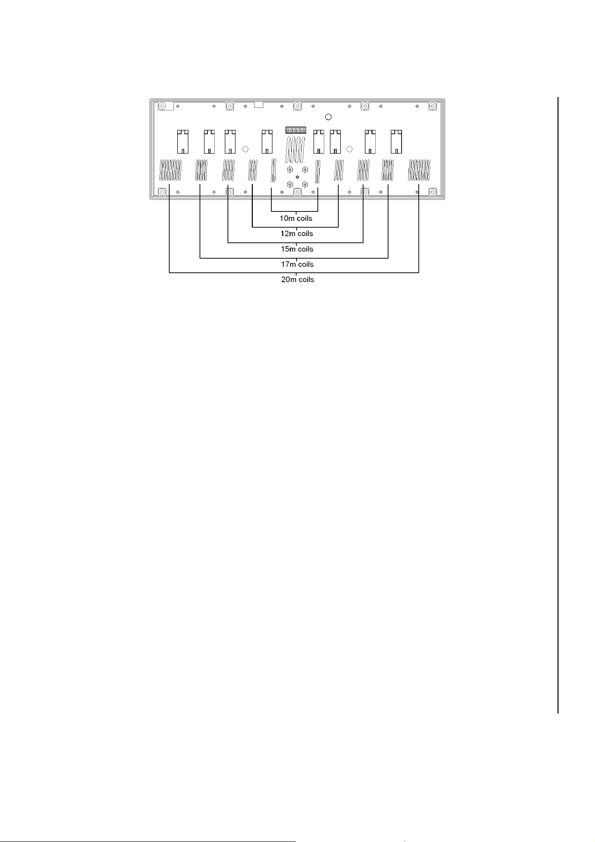
Switching Array Operation. All of the coils on the top half of the switching array
are series connected. A relay shorts the signal to the metal structure, bypassing
all of the coils above a given band (the bottom half of the switching array is
effectively a mirror image of the top half). The tuning for each band depends on
the tuning for the previous band. Therefore, tuning must start at the 10m coil pair
and progress in order up to the 20m band.
6
The antenna is pre-tuned to the center of the general portion of the phone band under circumstance that
may differ from the environment of your specific installation.
TW2010TM Instruction Manual 23
Page 25
Trans World Antennas
Equipment. The tuning process requires Voltage Standing Wave Ratio (VSWR)
measurement. These measurements can be accomplished using most any
antenna analyzer. However, these devices typically generate a very small signal
(less than 0.2W), and may show higher than expected VSWR readings. A
reading of 1.3:1 at the tuned frequency is typical at this low power. The VSWR
readings should decrease once the antenna is used with 5W of power or more.
The VSWR reading on your transceiver will likely show a lower VSWR than a
low-power antenna analyzer.
TW2010
TM
Cables. Make sure that the coax used for the tuning process is at least 65 feet
long, and that both the coax and control cable are installed at a 45 degree angle
as described on page 16.
24 TW2010TM Instruction Manual
Page 26
Trans World Antennas
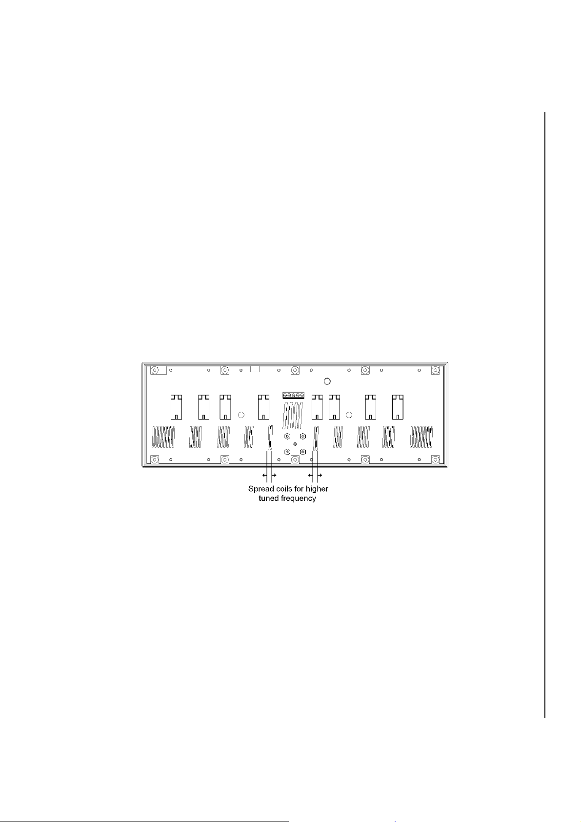
Tuning. To tune each band, each of two coils in the coil pair for that band must
be spread or compressed (see figures below). By spreading each coil in the coil
pair, the tuned frequency for that band will increase. Likewise, compressing the
coils in a coil pair will decrease the band’s tuned frequency. You should try to
spread or compress each of the two coils in a coil pair by the same amount.
1) Preparation. To begin the tuning process, remove the switching array cover,
as in step 1 on page 19 and connect the control and coax cables to the switching
array box, as described on pages 15 and 16. The coax you use for the tuning
process should ideally be the coax you plan to use for the antenna during normal
use. Connect the coax cable to the device you wish to use to measure VSWR,
and connect the control cable to your controller.
2) Start at 10m. Switch your controller to the 10m band and determine to what
frequency the antenna is best tuned. If you wish to increase the tuned
frequency, spread open each of the two coils labeled “10m” on the switching
array circuit board, as shown in the figure below.
TW2010
TM
3) Tune next band. Once the 10m band is tuned, switch your controller to the
12m band and tune the 12m band in a similar fashion as you tuned the 10m band
in step 2.
4) Repeat for remaining bands. Repeat the tuning process for the 15m, 17m,
and 20m bands, in that order.
TW2010TM Instruction Manual 25
Page 27
Trans World Antennas
Final tuning notes
Due to parasitic coupling, installing your antenna on the optional Quadrapod
stand may cause the tuned center frequencies to differ from those of a
permanent installation.
If lower bands exhibit very low VSWR, but higher bands suffer VSWR problems
(or vice-versa), the spacing of the center coil can be adjusted to effect which
bands tune best. By spreading the center coil slightly, the low-frequency bands
will tune better, and by compressing the center coil, the higher-frequency bands
will tune better. But note that if the center coil is changed, the tuned center
frequencies may change and the tuning process above will have to be repeated.
If tuning proves difficult, follow this checklist to eliminate common tuning
problems:
Is your antenna placed at least 30 feet away from other objects (buildings,
people, trees, etc.)? The ends of the antenna’s arms are very sensitive to
coupling with external objects.
TW2010
TM
Is your antenna installed such that the arms are at least 24” off the ground?
The spacing between the antenna’s arms and the ground should be between 24”
and 36”.
Is your coax cable a high-quality RG-8 or RG-8X cable?
Is your coax cable long enough? At least 65 feet of coax should be used for
best results.
Are your coax and control cables installed at a 45-degree angle with respect
to the antenna as in the figure on page 16?
Are you checking the VSWR using less than five watts? Once at least five
watts is applied to the antenna, VSWR readings may improve significantly.
26 TW2010TM Instruction Manual
Page 28
Trans World Antennas
TW2010
5.6 Fuse Replacement
To help protect your antenna and other equipment connected to it, the controller
is provided with an internal fuse. In the event that the fuse must be changed,
follow the steps in this section to change the fuse.
Fuse type. The fuse used by your controller is a 1-1/4x1/4 glass fuse rated at
200mA.
Warning: Replace only with the same type and rating of fuse. Failure to do
so could cause permanent damage to your controller, antenna, or other
connected equipment, and will void your warranty.
TM
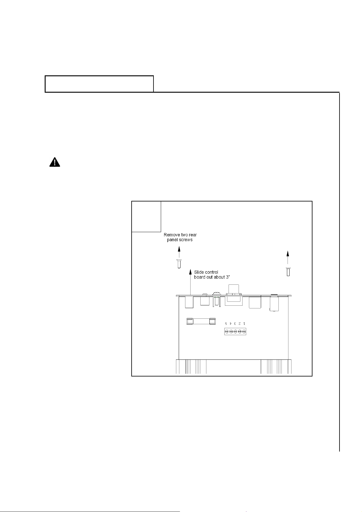
1) Open controller
enclosure. Remove
the two black rear
panel screws from the
controller, as shown in
step 1 below, and pull
the control board about
3” out of its enclosure.
Remove the controller’s two rear panel
screws and pull board out about 3”.
1
TW2010TM Instruction Manual 27
Page 29
Trans World Antennas
TM
TW2010
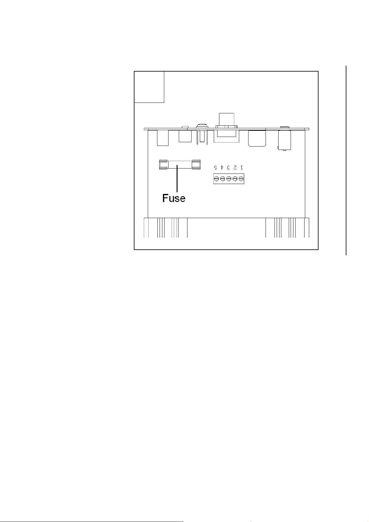
2) Replace fuse.
Carefully pull out the
old fuse. Install the
new fuse, making sure
the new fuse is 1-1/4 x
1/4, 200mA. Discard
the old fuse.
3) Replace control
board. Re-insert the
controller’s circuit
board back into its
enclosure and replace
the two panel screws.
Remove the faulty fuse and replace with
one of the correct type and rating.
2
28 TW2010TM Instruction Manual
Page 30
Trans World Antennas
TW2010
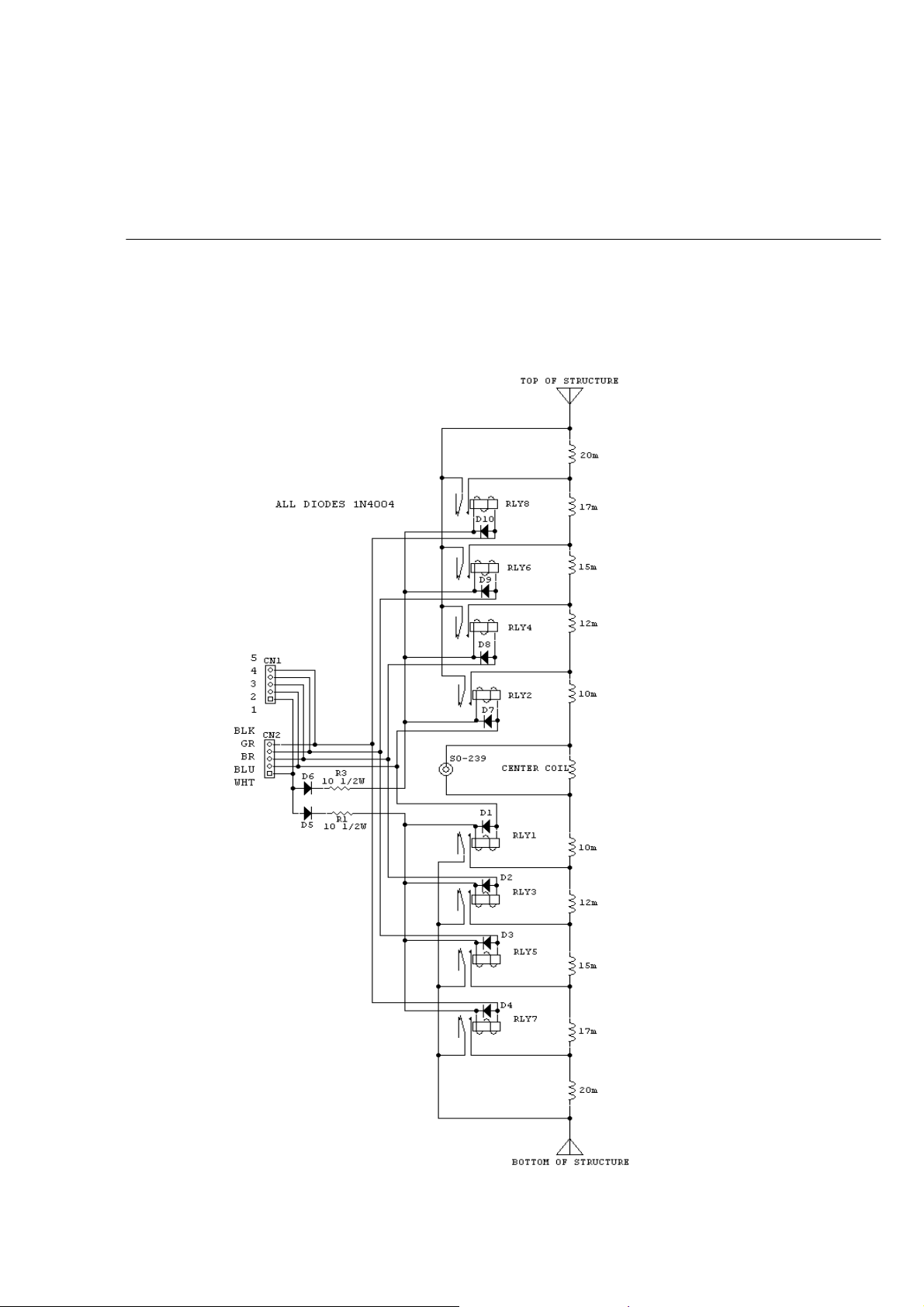
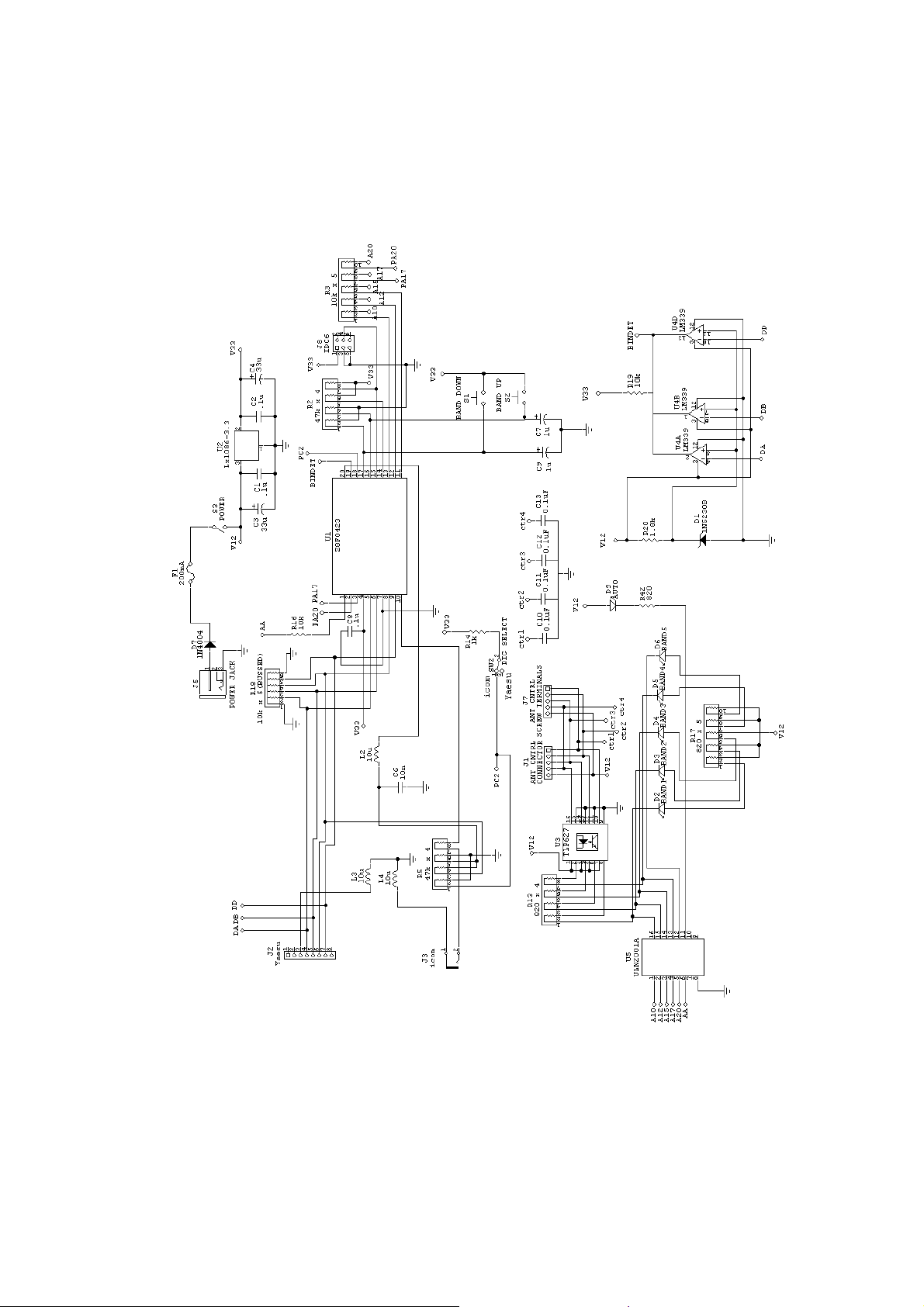
6 Schematics
This section contains the schematics for the TW2010’s TW-RB-1 switching array and TW-AC-1
auto controller.
TW-RB-1
Switching Array
TM
TW2010TM Instruction Manual 29
Page 31
Trans World Antennas
TW-AC-1
Auto Controller
TM
TW2010
30 TW2010TM Instruction Manual
Page 32
Trans World Antennas
TW2010
7 Accessories
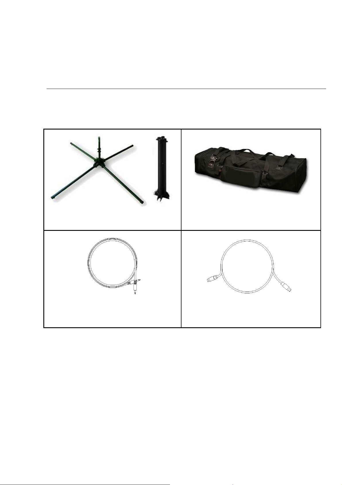
Below are the accessories available for your TW2010 antenna. Visit our website
www.TransWorldAntennas.com for more information.
TM
TW2010 Adventurer™ Quadrapod
Four-leg folding stand (22” tall, 45” x 45” footprint)
TW-AC-1-YC
Interface cable for use with select Yaesu
transceivers (8-pin mini-DIN, 6 feet)
TW2010 Adventurer™ Transport Bag
Handy travel bag to carry your TW2010 on field day
outings.
TW-AC-1-ICOM
Interface cable for use with select Icom
transceivers (1/8” mono, 6 feet)
TW2010TM Instruction Manual 31
Page 33

Trans World Antennas
TW2010
8 Contact Information
If you need to contact Trans World Antennas, just drop us an email at:
Use this email address for help with installation, setup, tuning, or operation, for
product or company information, or warranty/money back guarantee claims.
TM
Check back at our website frequently for product updates at:
www.transworldantennas.com
We can also be reached through our web-based contact system on the website.
32 TW2010TM Instruction Manual
 Loading...